http://www.diva-portal.org
This is the published version of a paper presented at Conference Tools for Materials Science & Technology (MSE 2010), 24-26 Aug 2010 Darmstadt, Germany.
Citation for the original published paper: Sadeghi, M., Mahmoudi, J. (2010)
Numerical determination of process parameters for fabrication of automotive component. In: solidification simulation
N.B. When citing this work, cite the original published paper.
Permanent link to this version:
Numerical determination of process parameters for fabrication of automotive
component
Mohammad Sadeghi1,a, Jafar Mahmoudi1,b
1
HST Department, MÄLARDALEN University, Sweden,
a
mohammad.sadeghi@mdh.se, bjafar.mahmoudi@mdh.se Conference Tools for Materials Science & Technology 2010 http://www.dgm.de/dgm/mse-congress/images/MSE_Programme.pdf
Abstract. The casting defects that are caused by molten metal are cold shut formation,
entrapment of air, gas, and inclusion. But the control of casting defects has been based on the experience of the foundry engineers. One of the most parameters that can influence the casting defects is cooling rate. In this paper, computer simulations have been carried out to analyze the flow of molten metal and effect of die temperature on the cooling rate and subsequently the casting defects. Flow patterns of molten metal in one of the Iranian automotive component were examined to find the optimal temperature for the die-casting die temperature. The finite element ProCast software was used for simulation and results of simulation was compared with the experiment. The calculated results for automobile Ladder frame body to control the die-casting process have achieved good agreements with the experimental data. Results show that temperatures between 20°C to 25°C are good for the die casting.
Keywords: High pressures die casting, process parameters, defect, Al alloy, ProCast. Introduction
In high pressure die-casting, usually known as pressure die-casting, molten alloy is injected under pressure into a highly accurate split metal mould. Die casting is a high volume manufacturing technology for parts of different size and shape, typically with thin to medium wall thickness. Production rates are high; labor costs are low and can further decrease by automation and process control. Consistency and repeatability are good. Accuracy and complexity of die-castings are better than most alternative castings processes, although undercuts are hard to form. Surface finish and appearance are good. Tolerances are moderate. Parts are manufactured to their near net shape with very little machining required in most cases. The process imposes limitations on properties of the casting alloys. High fluidity is essential since solidification is fast and the melt must fill the die in a very short time. Low thermal expansion is necessary to reduce shrinkage voids as thermal gradients in the die are high and directional solidification is hard to obtain [1].
Porosity, both air bubbles and shrinkage voids, and cold shut are a major issue in die casting. Thus, die castings are rarely used for critical load bearing parts. The suitability for heat treatment and welding has always been a measure of quality die castings. At elevated temperature required for heat treatment or welding, air bubbles expand to the surface and deform the casting if porosity is too high. The high pressure die casting process enables the casting of complex thin walled castings with good surface finish and dimensional tolerance. Molten metal is generally injected into the cavity via thin gates at high velocities promoting turbulent flow that can result
in air entrapment. Internal porosity is of significant concern for die casters, especially when castings receive subsequent machining operations. Whether porosity in a component results in the part being scrapped depends on its location, size and distribution. A small number of large pores may be unacceptable, while a component of the same density that has smaller more dispersed porosity may be acceptable [2].
Traditionally, gating system design is performed by casting process engineers based on their individual knowledge and experience. In many cases, the gating system design is not optimal and often based on trial and error practice. There are however, recommendations and directions based on geometry features and specifications. The goal of such simulations is to help shorten the design process and optimize casting parameters to reduce scrap, use less energy and, of course, make better casting [3-5].
Numerical simulation provides a powerful means of analyzing various physical phenomena occurring during casting processes. It gives an insight into the details of fluid flow, heat transfer and solidification Numerical solutions allow researchers to observe and quantify what is not usually visible or measurable during real casting processes. The goal of such simulations is to help shorten the design process and optimize casting parameters to reduce scrap, use less energy and, of course, make better castings. Simulation produces a tremendous amount of data that characterize the transient flow behavior (e.g., velocity, temperature), as well as the final quality of the casting (e.g., porosity, grain structure). It takes good understanding of the actual casting process, and experience in numerical simulation, for a designer to be able to relate one to the other and derive useful conclusions from the results. Most of the casting modeling codes can be divided into two Categories: those using the finite difference (FD) approach for solving fluid flow equations, and those that employ the finite element (FE) method. The FE method uses body-fitted computational grids leading to more accurate representation of metal/mould interfaces than generally achievable by FD methods[6,7].
Kermanpur and co-workers[5] used FLOW-3D software to simulate the filling and solidification sequences of two automotive components. They process the appropriateness of the running and feeding systems. Some other investigators works on optimization of process parameter for die-casting process by simulation [8-11].
In the high pressure die casting (HPDC) process using metallic dies, the production rate and the microstructure features are strongly dependent on the heat transfer through the casting/die interface during the solidification of the casting [12,13]
Normally, the main controlled variables are the mould temperature, slow and fast shots, gate speed, injection pressures, upset pressure, as well as the metallurgic quality, chemical composition and liquid aluminum temperature. In this work effect of die temperature on the formation of cold shot and porosity was studied by simulation. The simulation results were compared with the experimental results.
Problem Defining
The automotive part studying in this work is named Ladder frame (fig. 1). The material employed to produce Ladder frame was A380 aluminum alloy. The mechanical and thermo physical properties and chemical composition of this alloy are shown in tables 1 and 2 respectively. The main cause of the high number of rejections was due to the appearance of defects, as cold shuts, porosities and shrinkages, located in final filling positions and regions that needed to be machined. For the quality evaluation, a critical region of this part has been chosen, where the occurrence of this type of defect was high.
The IDRA1600 die-casting machine was used to injection of molten metal into die cavity.
In order to validate the simulation model, the filling time of each component was measured carefully by a precise stopwatch. The solidification time of the castings were determined by knocking out the moulds in different times after the pouring. A Minolta/Land Cyclops 152 infrared pyrometer was used to measure the die temperature just before pouring. All castings were cut transversely after cooling down to determine the location of any possible shrinkage.
Fig. 1: Geometry of Ladder frame part used for simulation Table 1: mechanical and thermo physical
properties of A380 aluminum alloy
Casting temperature 635-704 [ oc]
Solidus temperature 538 [ oc]
Liquidus temperature 593 [ oc]
Thermal conductivity 109 [W/m-oc]
Specific heat capacity 0.963 [j/g-oc]
Heat of fusion 389 [j/g]
Hardness 100 [HB]
Tensile strength 248 [MPa]
Yield strength 116 [Mpa]
Elongation 1.2 [%]
Table 2: chemical composition of A380 aluminum alloy [wt. %]
Aluminum ,Al 85.65
Silicon, Si 9.08
Copper, Cu 3.2
Manganese, Mn 0.21 Nickel, Ni 0.05 Tin, Sn 0.01 Zinc, Zn 0.64 Lead, Pb 0.08 Titanium, Ti 0.02 Chromium, Cr 0.01 Iron, Fe 0.84 Simulation
In order to perform the mould filling and solidification simulation of automotive part, the commercial finite element code Procast was used. Within the framework of an Eulerian description, this software is capable of solving simultaneously three-dimensional transient thermal and fluid flow problems with free surface. Procast was selected because its solver is FEM and present more precise results than FDM method in thin sections. The initial conditions used in simulation were set as the same of experiment and are shown in table 3. In order to evaluate the effect of die temperature on the casting quality three die temperatures, 150oc, 200oc and 250oc, were adapted while other simulation parameters were kept constant. Material properties used in simulation were extracted from the soft ware data base for A380 aluminum alloy. The cause of slightly different flow pattern in the cases of mold temperature 20°Cc and 25°Cc is that the viscosity of the fluid in the simulation was considered as a function of temperature.
Table 3: initial condition used in simulation Heat transfer coefficient 9 [kJ/m.K] [14] Number of finite element
mesh 700000
Plunger velocity 3 [m/s]
Melting temperature 780 [ oc]
Results and discussion
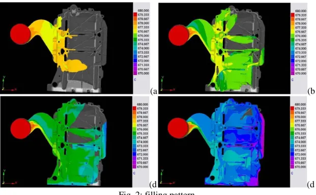
The filling pattern of the molten aluminum is shown in Fig. 2. It is after about 0.05s that the melt enters the gate and starts filling the cavity. The rest of the mould cavity is then filled up. The predicted filling time is about 0.12s that is in agreement with the observations.
(a (b
(d (d
Fig. 2: filling pattern
Fig. 3 shows the final filling position in the casting part. As mentioned before, three die temperatures (15°C, 20°C, 25°C) was considered in the simulation in order to evaluate the effect of die temperature on the filling and solidification defects. From the calculated results it is observed that in the case of 15°C die temperatures, temperature of the melt fall near the liquidus temperature of the alloy at the final filling position. This can result in the formation of cold shot and poor filling in that area. From the experiment this effect was validated and casting defect was observed in those areas. It was found that over flows must put in those areas. Fig. 3 shows the casting defects occurred in the final filling positions. This picture is referred to the die temperature of 15°C which shows that this die temperature is not adequate for the die casting. It is seen that these positions are in good agreement with the calculated results from the software.
Fig. 3: final filling position
Fig. 4 shows the entrapment of air site in the first stage of filling in the runner calculated with the soft ware.
Fig. 4: entrapment of air site in the first stage of filling in the runner
Fig. 5: Solidification patterns
The solidification of casting takes place about 6 s and the rest of the gating system solidifies approximately 40s afterwards showing a reasonable agreement with the measured values. The solidification pattern of the Ladder frame cast part just after filling is shown in Fig. 5. The melt solidification is started in the center of the part because these areas have less thickness from
around the part (Fig. 5) after about 1.7s, the gate is completely solidified and the solidification of the cast part starts from the center. This pattern of solidification causes formation of porosity in the outer side of the casting which is in good agreement with the experimental results (Fig. 6). Fig. 6 shows the regions of the part containing melt after that the gate was completely solidified. These regions are susceptible to the formation of shrinkage. This result was validated with the experimental results which are shown in the fig. 6.
Fig. 6: final solidification positions
As can be seen from this figure, the outer side of the part has shrinkage defects which were predicted with the software. The verified model interestingly represented the correct location of the hot spots in the castings. It should be noted that due to the automatic molding system being used, it was not possible to propose a suitable chilling system to avoid such micro-shrinkage. However, the simulation results showed that increasing the die-temperature is a practical parameter to significantly reduce the occurrence of such possible micro-shrinkage at this location. The simulation results for casting clearly demonstrated that gate is properly solidified prior than the castings, making it possible for the melt to compensate its contraction during solidification by the expansion of graphite phase such that no riser is needed. It can be concluded that in order to establish a similar heat transfer and solidification conditions, it is necessary to consider symmetrical configuration.
This results show that die temperature of 15°C is not appropriate for the die casting of this part and in order to eliminate the defects, it is essential to increase die temperature. Also results show that 20°C and 25°C is more appropriate for die casting.
It is able to study the effects of several casting parameters including the melt superheat, pouring time (velocity), mould surface roughness, gating design, and the mould configuration on the
quality and soundness of automotive cast parts with simulation. The present simulation model clearly shows the capability of analyzing the fluid flow and solidification behaviors of the complex casting part. The model is continued for considering other parameters of casting on the quality of the part.
References
[1] M. Merlin, G. Timelli , F. Bonollo, G. L. Garagnania” Impact behaviour of A356 alloy for low-pressure die casting automotive wheels” J. Mater. Pro. Tech. Vol. 209 (2009), pp1060-1073. [2] M. Dargusch, M. Nave, P.McKinney “Porosity Reduction in a HighPressure Die Casting ThroughThe Use of Squeeze Pins” NADCA (2003), pp405-412.
[3] J.X. Zhou, L.L. Chen, D.M. Liao, R.X. Liu: J. Mater. Pro. Tech. Vol. 192–193 (2007), pp 249–254.
[4] Z. Sun, H. Hu, X. Chen: J. Mater. Pro. Tech. Vol. 199 (2008), pp256–264.
[5] “FAILURES OF DIES FOR DIE-CASTING OF ALUMINIUM ALLOYS”, METABK 47(1) 51-55, 2008.
[6] A. Kermanpur, Sh. Mahmoudi, A. Hajipour, “Numerical simulation of metal flow and
solidification in the multi-cavity casting moulds of automotive components”, J. Mater. Pro. Tech. Vol. 206 (2008), pp62-68.
[7] D. McBride, T.N. Croft, M. Cross: Computers & Fluids, Vol.37 (2008), pp170–180.
[8] Z. Brown, C. Barnes, J. Bigelow - Contech U.S., Kalamazoo “Squeeze cast automotive applications and design considerations”, 4Th International Conference High Tech Die Casting 9-10 April 2008, Montichiari, Italy.
[9] V. Ilotte “ Die casting for chassis components” 4Th International Conference High Tech Die Casting 9-10 April 2008, Montichiari Italy.
[10] G. Timelli, F. Grosselle, F. Voltazza, E. Della Corte “A new reference die for mechanical properties evaluation in diecasting Part 1 - Design and process optimization” 4Th International Conference High Tech Die Casting 9-10 April 2008, Montichiari Italy.
[11] B.S. Sung, I.S. Kim “The molding analysis of automobile parts using the die-casting system” J. Mater. Pro. Tech. Vol. 201 (2008), pp635–639.
[12] Z. GUO, S. XIONG, S.H. Cho, J.-K. Choi, “Heat Transfer between Casting and Die during High Pressure Die Casting Process of AM50 Alloy-Modeling and Experimental Results”, J. Mater. Sci. Technol. Vol.24 (2008), pp131-135.
[13] G. Muneratti “Role, functions and heat transfer of die coating in the aluminum die casting process” 4Th International Conference High Tech Die Casting 9-10 April 2008, Montichiari Italy. [14] P. J. Pearson, “Contact heat transfer coefficients in aluminum alloy die casting: an