Scientific Press International Limited
Dams Safety and Geology
Nasrat Adamo1, Nadhir Al-Ansari2, Varoujan Sissakian3, Jan Laue4 and Sven Knutsson5
Abstract
Geological hazards that can face dams are very important in deciding their safety and successful performance during their lifetime without excessive and costly repairs. Recognizing such hazards must be made at an early stage of the investigation works. Geological hazards which have caused dam failures or resulted in redundant reservoirs can vary between presence of karsts in the reservoir or in dam foundation, presence of soluble rocks, hidden faults, or the presence of hazardous materials. Learning from case histories of dam failures and incidents is important to avoid problems raised by these hazards.
Many such cases are presented in the preceding paragraphs to show the variety of such problems and help understand their nature. These case histories, can help the designer in the selection of the most appropriate type of dam suited for a particular geological condition, avoiding dangerous situations such as but not limited to excessive or differential settlement. Understanding the real conditions of foundation decides also the efficiency, scope and type of foundation treatment. The Teton dam failure given in this paper illustrates one case when such understanding was missing. In any case, the active participation of geologists working with the designers in all stages of dam construction process is very important to eliminate or reduce to safe limits any geological hazard that can the future dam.
Keywords: Geological Hazards, Geological Investigations, Karsts, Faults, Soluble
Rock, Foundation Treatment.
1 Consultant Dam Engineer, Sweden.
2 Lulea University of Technology, Lulea, Sweden.
3 Lecturer, University of Kurdistan Hewler, and Private Consultant Geologist, Erbil. 4 Lulea University of Technology, Lulea, Sweden.
5 Lulea University of Technology, Lulea, Sweden.
Article Info: Received: June 9, 2020. Revised: June 18, 2020. Published online: July 10, 2020.
1. Selection of Safe Dam sites
The most important elements in dams’ sites selection are topography and geology. While topography defines the size of the dam; its height, length and volume of reservoir, geology, on the other hand dictates the possibility of building safe dam with respect to tightness of the reservoir, stability of the reservoir slopes, in addition to the foundation conditions of the dam itself. Economic and financial factors play their role in site selection when figuring the amounts and costs of foundation treatment required for a safe and reliable dam.
It is important to emphasize here that no restrictions should be put on the magnitude of geological investigation required for site selection and for sound planning and design; as far as the cost is concerned. This cost should be commensurate to the importance of the dam, and the safety hazards that it can create to society. Moreover, this cost is normally payed back by choosing a more economical design with enough level of safety to answer for the worries related to loss of human life and other material losses as expressed by the society and its institutions, in addition to trouble free performance, which will, at the same time, cuts on the cost of operation and maintenance of the dam.
It is not intended here to define the detailed requirements for the geological investigations necessary for selecting a good and safe dam site free from risks, as this must be done case by case, but a general outline only may be given.
For preliminary studies, the dam site investigations shall concentrate on selecting the dam axis and the locations of the appurtenant structures considering the best topographical and geological features by utilizing geophysical surveys, drilling boreholes and excavating some test pits and trenches or even investigation galleries if required. Sampling and laboratory testing of soil and rock samples then follow. At this stage, inspection of the reservoir area is warranted to check for salient features such as potential landslides, which may threat the future dam safety, and sinkholes or karst that reduces reservoir tightness or even endangers the stability of the dam. Failure to do this may lead to catastrophes like the Vajont Dam land slide which caused the death of thousands of people, or may lead to creating a redundant dam if the reservoir water leaks out unhindered as the cases of Hondo Reservoir in New Mexico, Cedar Canyon Dam in South Dakota and Anchor Dam in Wyoming (USA). Anchor Dam was built despite more than 50 sinkholes and stream losses associated with karstified Triassic gypsum that was reported for the reservoir area. During the first attempt to fill the reservoir, numerous additional sinkholes were reported. A collapse around 100m across and 20m deep occurred upstream of the concrete dam and was isolated by the construction of an additional dike that limited the operational water level of the reservoir and reduced by 50% its storage capacity. After 30 years of costly attempts to repair the reservoir, it has never held more than a small pond [1]. For large dams, where safety must be reasonably ensured beyond any doubt, the next stage of the geological investigations shall be detailed and must concentrate on getting accurate description of the foundation stratigraphy and structural setting by getting full geological profile along the dam axis which should
extend to a safe distance in the abutments. Moreover, geological cross sections at selected points along this axis and at appurtenant structures locations must be prepared. All this shall be accomplished by driving deep boreholes extending down to depths (deeper than the foundations) sufficient to catch any possible geological anomaly. In situ permeability test may also need to be carried out in these boreholes to give a representative permeability picture at the various depths under the dam, while soil and rock samples shall be obtained from these boreholes for laboratory testing to investigate the type of rock, their properties and strength characteristics. Moreover, these boreholes should be geophysically logged to indicate any ambiguous data acquired from geological mapping. Design engineers and field geologists must be well versed in the geological hazards that threaten the safety of dams and should be capable of interpreting the geological finding correctly. According to any special situation, these may include among other things appreciation of regional earthquake hazards and dangers inherent in the proximity of dam sites to potential or actual active faults. Other important factors shall be studied carefully and not overlooked such as; potential landslides, the presence of karsts and soluble rocks, foundations containing compressible layers, expansive soils or weathered rock, existence of faulting under the dam and their orientation, presence of weak sliding surfaces such as thin seams of clay, etc. The extent of foundation treatments required to attain the prescribed safety level shall be decided on the light of these studies with the aim of eliminating all potential geological hazards.
2. Land Slides Hazards
The subject of landslides has been treated in some details in a previous paper entitled “Dam`s safety and Earthquakes” written by the authors; it deals with earthquakes as the prime cause of landslides of mountain slopes into reservoirs and the hazards they may create to dams, so the reader is invited to refer to it as a complementary reading.
Many dams and reservoirs are constructed in steep mountainous terrain where landslides can occur. Landslides, if large enough, can affect the safety of a dam or reservoir if they fail or move. Landslides generally are triggered by the saturation of soil mass, which may slide down in shear failure along some weak layer within the geological beddings within the slope. The chances of such failure are intensified by wetting of the mass from excessive rainfall, snowmelt, or large earthquakes, also from the quick draw down of the water level and are called “reservoir induced landslide”. Landslides are additionally affected by anthropogenic factors associated with the filling or operation of the reservoir, e.g. morphology of the flooded slope, road cuttings on the reservoir rim, changing in the course of shoreline or considerable rapid reduction of water level and such sudden changes that affect hydrostatic groundwater pressure in the slope.These factors often coincide leading to a sudden drastic decrease in slope stability increasing the activity of landslide. The rise in pore water pressure on the slope results in changes in geotechnical
parameters of the soil, mostly reducing its cohesion and shear strength and increasing its weight and bulk density [2]. Old landslides can be reactivated, if the geologic conditions are adverse, new landslides can be triggered. New landslides develop in most cases after some recent activities, which drive the soil or rock mass gradually to a state of limiting equilibrium, such as impoundment of the reservoir, excavation of a new road cut, or other disturbances to the area. Landslides can occur upstream in the reservoir, in a canyon downstream of a dam, or even within the
abutment of a dam. An idealized form of landslides is shown in Figure 1 with the commonly used
nomenclature [3].
Figure 1: An idealized landslide and commonly used nomenclature [3].
Landslides occurrence can take many scenarios: The first one is when such landslide falls in the reservoir of an existing dam, the second is when it occurs downstream from an existing dam, and the third is when a new dam is built abutting an old landslide which starts moving after construction of the dam. For the first scenario, if a landslide is failing into the reservoir, and if it is close enough, large enough, and moving fast enough, it can generate a wave large enough to overtop a dam. Sloshing back and forth in the reservoir can result in multiple waves overtopping the dam. If the waves are large enough, downstream consequences can result just from the downstream overtopping flows even if the dam does not fail. If enough large waves overtop an embankment dam or a concrete dam with erodible abutments, an erosion failure could potentially result. One catastrophic case of landslides in conjunction with dam reservoir is the Vajont Dam reservoir landslide. This event occurred on October 9, 1963, at 10:39 pm when 260 million cubic meters of rock broke off from the top of Monte Toc, on the border between Veneto and Friuli Venezia Giulia. It
fell into the reservoir of the Vajont Dam, producing an enormous wave of at least 50 million cubic meters of water. The dam completed in 1959 and one of the biggest in the world at the time did not suffer any serious damage. However, flooding destroyed several villages in the valley and killed almost 2,000 people. A third of the population of Longarone, the largest village downstream from the dam, perished [4], refer Figure 2. Post-failure investigations showed that low strength clay layers existed between the limestone beds. It was surmised that rainfall on the mountains above the reservoir was conveyed through solution features to the reservoir slopes where it became trapped by the impermeable clay layers. A review of the landslide survey data showed that movement accelerated with a high reservoir level following periods of heavy rain. Thus, it was the combination of high reservoir level, which unweighted the toe of the slide, and heavy precipitation which increased the pore pressures in the rocks of the slope, that lead to triggering of the slide on weak clay layers. This was confirmed by limit equilibrium analyses that considered side constraint afforded by a fault on the upstream side of the landslide mass [5] and [6].
Figure 2: View of the Vajont reservoir after the landslide (1963)[4].
In the second scenario, when a landslide occurs downstream of a dam, it can then block the river course creating a landslide or debris dam. The water impounded by a landslide dam can create a dam reservoir (Lake) that may last from short times to several thousand years, and because of their rather loose nature and absence of controlled spillway, landslide dams frequently fail catastrophically and lead to downstream flooding, often with high casualties. A common failure scenario is overtopping with subsequent dam breach and erosion by the overflow stream. Operational releases from an existing upstream dam can also overtop and erode the
debris dam, sending a large slug of potentially life-threatening flows downstream. In such case, releases from the upstream dam must be controlled with caution, which may limit these releases and consequently, limit the benefits derived from the operation of the dam such as power generation or irrigation. While damages can occur whether there is a dam upstream of the landslide or not, having an upstream dam creates added complications. In an emergency case threatening the safety of the upstream dam, say from large earthquake ground shaking or any other reason, it may not be possible to lower the reservoir for fear of overtopping the debris dam. In flood control operations and when necessity requires high releases from the dam, these releases can cause overtopping erosion failure of the debris dam and a sudden surge of water downstream. For this reason, there may be pressure on the dam operators to hold back the downstream flows. If the flows cannot be held back, it will likely become the task of the dam operators to issue warnings. For all these reasons, it is necessary to have a fair idea and good understand of the geology in the canyon downstream at an early stage during the investigation and planning of the dam and to recognize the potential development of this type of l failure mode in the future. There is also the possibility that high-water levels created upstream from the landslide dam may impound the downstream facilities of an upstream dam causing damages and might even take out these facilities out of operation. Giving some examples of the occurrence of some landslide’s dams may be done to highlight the magnitude of the impacts of such dams on river courses and the extent of dangers they pose to existing dams if they are close enough to such dams. One such example in modern history is Usoi Landslide Dam in Tajikistan created by a landslide triggered by an earthquake on February 18, 1911. It dammed the Murgab River to the height of 570m (1,860ft) to impound Sarez Lake 505m (1,657ft) deep. The second case is the Lake Waikaremoana in New Zealand which was formed by a 250m (820ft) high landslide dam believed to be 2,200 years old. Between 1935 and 1950, the landslide was tunneled and sealed to stabilize it so it could be used for hydroelectric power generation. This appears to be the first example of modification of a natural landslide dam for power generation. Among the most destructive landslide lake outburst floods in recorded history is the one that had occurred in the Sichuan province, China, on 10 June 1786 when the dam on the Dadu River burst, causing a flood that extended 1,400km (870 miles) downstream and killed 100,000 people [7].
In some cases, dams have been built abutting against a landslide. Often, these are ancient landslides that have stopped moving, or are moving very slowly. However, if such a landslide moves far enough, it can crack the core of an embankment dam, resulting in pathways for internal erosion to initiate, or disrupting the abutment support of a concrete dam, resulting in cracking and structural collapse of the concrete. If a thin upstream member, such as a reinforced concrete facing, forms the water barrier for an embankment dam, landslide movement can lead to buckling of the slab, and flow through large cracks, which may be capable of eroding even large rockfill forming the downstream shell. If the abutment of an embankment dam contains a landslide, limit equilibrium analyses, including possibly reliability
analysis, can be made to estimate the likelihood of the landslide moving under various loading conditions (i.e. earthquake loads ranges, flood loads ranges, and/or ground water ranges). These load ranges can be put on the front end of an event tree and the likelihood of cracking estimated for each. If cracking is recognized as a possibility, then all measures to limit internal erosion must be considered to decrease the risk of failure. It must be emphasized, however, that sites with potential landslides shall be avoided altogether by carrying good and intensive investigation, whether by drilling and geophysical surveys, at the proposed site.
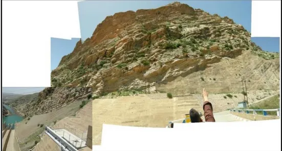
If a landslide, very close to the upstream face of the dam, is triggered by a large rainstorm, then damage to a spillway or other outlet features can occur at the same time when large reservoir inflows are occurring. If the landslide debris block the spillway or intakes or damages them to the point that they cannot be operated, then premature overtopping of the dam may occur. In this respect the case Derbendikhan Dam landslide in Iraq may be given as an example of such potentially dangerous landslide and what actions may be taken to stabilize it.
Derbendikhan Dam is located on the Diyala river approximately 65km south-east of Sulaymaniyah and 230km north-east of Baghdad. The scheme is a multi-purpose hydro-complex and the main structure is a 128m high embankment dam with a central clay core and rockfill shoulders. The crest length of the dam is 445m. The dam is constructed in a narrow steep-sided gorge on a series of sedimentary rocks including, marls, sandstones, limestones and conglomerate.
The reservoir impounded by the dam had a total design capacity at the normal operating level (El. 485.00m a. s. l) of 3,000 Mm³, of which 2,500Mm³ is live storage and 500Mm³ being dead storage. The current storage volumes will be less than this due to almost 60 years of sedimentation. The reservoir is controlled by a gated spillway structure located on the right bank and comprises three tainter gates installed on an ogee shaped overflow section followed by a steep chute terminating in a deflector bucket. Dividing walls separate the discharges from each of the three gate openings. The maximum discharge capacity of the spillway at the normal operating level (El. 485.00m a.s.l) is 5,700m³/s and 11,400m³/s at design flood level (El. 493.50m a. s. l).There are two low-level outlet tunnels (6m and 9m diameter) connected to steel conduits, which discharge water through three irrigation valves. The conduits also originally supplied water to two small turbines for the service generating station and are now connected to the three large turbines of the new powerhouse. An intake tower for the irrigation outlets is located between the spillway approach channel and dam embankment. The intake tower houses three vertical lift gates, gate No. 1 serves the 6 m diameter tunnel; gates No. 2 and No. 3 serve the 9m diameter tunnel. Construction of the dam started in 1956 and was completed in summer 1961. Five years after first impounding of the reservoir, slip failure of an area of the right bank some 300m upstream of Derbendikhan Dam was identified in November 1967. The affected area, consisting of about 2Mm³ of material approximately 350m in length and 200m wide, moved 1.5m downwards at reservoir elevation 455m following 126mm of rainfall over a period of 7 days, refer Figure 3.
Figure 3: Rock cliff above right abutment overlooking spillway chute at left, and landslide area at right lower part of the picture.
Additional settlement of the right bank slip area occurred between November 1969 and January 1970. A further failure of this slip mass represents a threat to the safety of Derbendikhan Dam as it could potentially cause the following:
a. Blocks the area immediately in front of the inlets and the spillway, restricting the volume of water that could be safely passed through the irrigation outlets, hydropower tunnel intake and over the spillway in the event of an extreme flood
b. Water displaced by the slip mass could cause a flood wave to overtop the dam crest, if the slip failure occurred at its highest reservoir level.
It is therefore, extremely important that a long-term solution for the stabilization of the right bank is achieved in the interests of dam safety.
Some remedial works for the stabilization of the slip area were proposed by a French Consultant consisted of:
a. Unloading of the slip area by excavation and removal of slip material above elevation 488m a.s.l.
b. Surface protection of the slip area by a drainage system and by landscaping to minimize the infiltration of rainwater
c. Construction of 9 wells with horizontal drains at the bottom, equipped with pumps to lower the phreatic surface within the sliding zone (deep drainage) d. Restriction of the reservoir drawdown to a minimum level of 460m. These remedial works were commenced in 1979, but they remain incomplete as they were halted in October 1980 due to the Iran-Iraq war affecting activities at the site. The status of the remedial work at that time was reported to be:
a. Excavation of 120,000m³ above elevation 488m nearly completed, but not assessed by topographic survey.
b. Placement of topsoil for landscaping not started.
c. Excavation of 7 wells were started; well P-2 collapsed and was replaced by well P-56; wells P-3 and P-7 were completed including the sub-horizontal drains.
d. Installation of 12 piezometers completed.
In January 1981, complementary stability analyses by the same consultant indicated that the minimum reservoir level could be revised and lowered to 455m.
The dam inspection carried out by a second consultant in January 1998 suggested that no significant movement of the right bank slip area had occurred since 1986, despite the drawdown of the reservoir to level 442m in 1988. New cracks on the ground were observed in April 1998, possibly indicating further movement of the slip mass, but the development of these cracks could also be partially attributed to surface run-off erosion during several days of high intensity rainfall.
In September 1999, the reservoir level was once more drawn down below the recommended safe level of 455m and the first consultant was engaged again to assess the risk of movements. The following recommendations were given in
December 1999: a. Installation of pumps in the completed wells and start draining the wells.
b. Cleaning of the sub-horizontal wells.
c. Collection of rainfall runoff by installing surface drainage.
d. Cleaning of existing piezometers. e. Survey of all existing beacons to monitor movements.
f. Underwater survey of the concrete slabs installed at the toe of the slip slope (these were last surveyed in November 1978).
g. Improve/complete the landscaping of the slip area.
The status of the wells installed in the right bank slip area was followed and summarized, and analysis was carried out by the consultants in 2006 to examine the behavior of the slip area. Their report makes further recommendations for the continued monitoring of the slip area and short-term measures.
The main recommendations can be summarized by: a. The allowable minimum drawdown level of the reservoir may be reduced to
elevation 450m, provided that a maximum drawdown rate of 10cm/day is not exceeded.
b. Urgent attention to reinstating/establishing an effective network of surface drains to intercept surface off and protect the slip area from surface run-off erosion.
c. Urgent attention to the cleaning of the sub-horizontal drains in existing wells to maximize their drainage efficiency.
d. Continues monitoring installed drainage wells collection of pumping data to assess the performance of the existing well installations.
The conclusions of the report were that, in order to achieve the minimum drawdown level of 435m (original design) and restore the full operating capacity of the reservoir, the current data suggests that the sub-horizontal drains in wells P-1, P-6 and P56 should be installed, a seventh well (P-15) installed and the surface drainage/landscaping of the slip area completed. The report also suggests a two-stage approach towards the realization of the long-term aim of the remedial works (i.e. a safe minimum drawdown level of 435m):
a. Immediate (short-term) implementation of the main recommendations
indicated above. b. Reassessment of the slip area behavior after a further period of monitoring
to determine whether all or part of the outstanding remedial works per the original remedial works design) is necessary to secure satisfactory conditions within the slip area for the safe drawdown of the reservoir level to 435m.
There is still, however, no firm evidence, which confirms that the proposed deep drainage system will achieve its final objective and keep the phreatic surface in the slip mass below or at the limits required for safe conditions with the reservoir drawdown to its intended minimum operating level of 435m. The 2006 analysis yields factors of safety against a deep sliding failure (down to elevation 405 m) of only Fs=1.13 to 1.14 (reservoir level 455m) and Fs=1.10 to 1.11 (reservoir level 450m). These results are below the normally accepted minimum factors of safety required by international standards for load cases without earthquake load. There is therefore, a real concern that the proposed deep drainage system will not be able to achieve its objective and satisfy international standards for slope stability. Furthermore, the design concept of the deep drainage system relies on the continuous reduction of the water table in the right bank area by pumping water from the well installations. This will require maintaining a continuous power supply to the pumps, ensuring that the pumps are regularly maintained, and adequate spare parts are readily available; failure to keep up the required level of maintenance will result in an increased risk to the safety of Derbendikhan Dam. Whilst alternatives for a permanent solution may require a greater capital investment (since significant investment in the deep drainage system has already been made), the ongoing maintenance costs of the deep drainage system may also mean that an alternative solution with no associated maintenance costs could be economically advantageous. A no or low ongoing maintenance’ solution would also present a lower risk to the safety of Derbendikhan Dam.
A common solution for the long-term stabilization of a slip area is to load the toe of the slope. Given the proximity of the slip area to the power intake structure, irrigation outlets and spillway, consideration may be given to the placement of interlocking pre-cast concrete blocks to load the toe area. Whatever the design of the permanent solution, the impact that any proposed remedial works will have on the performance of the intakes, and the spillway needs to be evaluated and properly accounted for [8].
mass and reduce the possibility of complete failure were to reduce the weight of the sliding mass by removing sizable part of it from the top, lower down the phreatic surface by pumping seepage water from deep drainage well and to bring this surface below the slip surface, and finally to reduce infiltration of rainwater into the mass which raises the phreatic surface by collecting rain water by good surface drainage and remove it from the slip area, and finally by limiting the drawdown the reservoir as a higher water level offers a stabilizing force exerted on the mass and increases its stability. Such work requires continuous operation of the pumps, in addition to
continuous revision of the stability and the operation rules of the reservoir. Limiting the drawdown of the reservoir water level and not being able to reach the
designed lower operation water level represents a loss of valuable storage capacity and all the benefits associated with it, while at the same time reaching this level poses a real threat by accelerating the movement of the slip mass.
The presented solution and performed works are of doubtful nature and requires constant vigilance and high maintenance costs, which emphasizes the need for a permanent solution, especially as the dam is located in an active seismic area which adds to the instability condition of the slip area. This safety problem is exasperated by the latest 7.3 magnitude seismic event the dam was subjected to, which occurred on 12th of November 2017. This earthquake struck the Iraq-Iran border with the epicenter in the Iranian city of Sarpol-e Zahab whereas Derbendikhan was the most impacted city in Iraq. The earthquake was one of the largest earthquakes occurring in the Iran–Zagros Zone since 1900. About 396 lives were lost, and 7000 people were injured on both sides of Iraq–Iran border, with most fatalities occurring in the city of Sarpol-e Zahab, whereas Derbendikhan was the most impacted city in Iraq. The earthquake struck the northeast of Iraq, with its epicenter 30km away from the Derbendikhan dam, and there is now a serious concern about the Derbendikhan dam’s and the landslide safety.
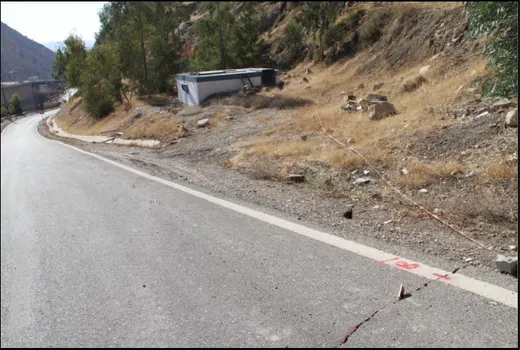
The dam was previously evaluated to be seismically safe under a maximum probable shaking of Mw 6.5, and no study is done for the seismic stability of the landslide. Furthermore, it was reported, however, that there was further concern about the landslide in the right bank upstream of the dam and rock falls from the high cliff in the left bank. The deformation of the dam body after the earthquake is visually apparent, and the State Commission on the Survey of Iraq observed several fissures on the crest soon afterwards. In the following months, this region exhibited 53 aftershocks with Mw > 4 [9]. A preliminary inspection was carried out by a team from the Ministry of Water Resources, which documented the cracks in the dam body and one new crack in the area above the limits of the landslide shown in Figure 4, but it seems that this team did not check new cracking in the landslide area which is located below the access road to the dam [10].
Figure 4: Location of a crack along the area above the landslide area (Crack is marked by red and white rope) and then extends down across the paved
road down into the landslide area.
In a paper entitled “Global Losses from Land Slides Associated with Dams and Reservoirs” it is stated also that the risk of landslides can be exasperated by the seismic activity resulting from impounding large reservoirs known as Reservoir Induced Earthquakes (RTS). From a technical perspective, it may be said that seismic activity can profoundly alter the rates of activity of the landscape, such as that conditions that apply during a site investigation phase may no longer be current [11]. It seems that no meaningful technical evaluation of the dam and the landslide area has been carried out so far, which reflects the state of negligence of a government which is sunk in corruption and political bickering not giving heed to a safety risk which threatens millions of the population of Iraq. The consequences of complete failure of this mass are grave as already stated. It should be remembered that the breaching of the dam in case of overtopping may lead to a flood wave in the downstream of the river and the possible failure of Hemren dam, which is located further down on the Diyala rivers. This can lead to national catastrophe by flooding very large area, including the capitol Baghdad. If a landslide exists in a concrete dam foundation, movement can also cause cracking of the dam. Similar methods to those summarized above for embankment dams can be used to evaluate the potential for movement, except that internal erosion is not the issue, but adverse cracking, isolation, and displacement/rotation of the isolated blocks of concrete in the dam could be. See the section on Risk Analysis for Concrete Arch Dams for some ideas on how to evaluate the risks associated with this. If movement of the landslide results in loss of abutment support, such that the dam moves with the
landslide, the methods in the section on Risk Analysis for Concrete Arch Dams to sliding of foundation blocks can be used to evaluate abutment stability and potential risks.
3. Karst and Soluble Rocks Hazard
Karst is a topography formed from the dissolution of soluble rocks such as limestone, dolomite, and gypsum. It is characterized by underground drainage systems with sinkholes and caves, refer Figure 5 [12]. It has also been documented for more weathering-resistant rocks, such as quartzite, given the right conditions. Subterranean drainage may limit surface water, with few to no rivers or lakes. However, in regions where the dissolved bedrock is covered (perhaps by debris) or confined by one or more superimposed non-soluble rock strata, distinctive karst features may occur only at subsurface levels and can be totally missing above ground.
Dams are costly structures whose failure can lead to disaster, large scale mortality and financial liability. Water leakage from reservoirs through ponors, sinkholes and karst conduits can lead to costly inefficiency, or even project abandonment. The unnaturally high hydraulic gradients induced by the impounded water may flush out of the sediment that blocks karst conduits. It can also produce the rapid dissolutional enlargement of discontinuities, which can quickly reach break-through dimensions with the turbulent flow. These processes may significantly increase the hydraulic permeability of the dam foundation on an engineering time scale leading to instability and failure of the dam.
The main reason of limestone karstification is the dissolving of the limestone by carbonic acid, which is formed by reaction of rainwater with carbon dioxide from the atmosphere. However, the formation of gypsum karstification is accomplished by reaction of oxygen (O2) in surface water, which seeps into the ground and reacts
with sulfide in the system forming sulfuric acid, which then reacts with calcium carbonate causing increasing erosion within the limestone beds. The abundant presences of carbonate sedimentary rocks all over the world and the existence of ambient conditions for the formation of karst has resulted in the existence of extensive karsts areas. But the intensive use of water resources during the last century resulting from the great expansion of economic activities dictated extensive utilization of water resources for irrigation, power and drinking water, which in turns has increased the need for constructing dams and other water related engineering works. Building of more and more large dams and reservoir in karst areas has brought up with it many engineering problems related to karst hazards, which require special attention and understanding.
Figure 5: Karst features characterized by sinkholes, caves, and underground drainage systems[12].
Generally, seepage through the foundations and abutments of dams containing soluble rocks may produce settlements and redistribution of pore pressures, which could threaten stability or cause leakage and waste of water sufficient to render the dam uneconomic. If joints or fissures exist in the soluble rock at dam sites, then various kinds of preventive or remedial measures may be considered to provide satisfactory and economic designs. It may, however, be demonstrated by thorough technical and economic studies that a chosen site is unsuitable. If such joints or fissures in the soluble rock abutments or foundations carry sufficient seepage flow of aggressive water, they can enlarge, and flow rates can increase unacceptably. One preventive method is to grout the joints or fissures and thereby seal the flow passages subject to the findings of such studies.
Such hazards; as excessive settlement and/or formation of sinkholes close or under the dam have to be securitized and carefully investigated. A suitable preventive measure might be to construct a groundwater cut- off “upstream” through the soluble rocks. It may be concluded, therefore, that engineering structures founded on or in soluble rocks are at risk if water moving through them is unsaturated in respect to soluble rocks. It is important to anticipate such a possibility during the geological investigation and planning stage and recruits the help of hydrogeologists to evaluate the situation correctly, and if the construction of the dam is to go ahead, then proper protection measures shall be included in the design [13]. The construction of dams and reservoirs in gypsum karst areas locally increases hydraulic gradients and raises a water table in previously unsaturated rocks. Both effects can lead to enhanced dissolution if gypsum rocks occurring at the foundation
of a dam construction or within the zone of influence of a reservoir. This can lead to leakage from a reservoir and cause collapses affecting dams and/or the areas surrounding reservoirs. As dissolution of gypsum is much faster than that of limestone, these problems are potentially more severe in gypsum karst than in carbonate karst terrains.
There are numerous examples of dam failure and reservoir leakage due to accelerated development of gypsum karst in many countries. The most infamous failure associated with gypsum was in California, USA, where the St. Francis Dam failed in 1928, at the cost of more than 400 lives and millions of dollars in damages. The problem was associated with dissolution of gypsum that was cementing and filling fissures in gypsiferous conglomerate in the dam foundations. Among other, example is the Quail Creek Dam, Utah, constructed in 1984 failed in 1989, the
underlying cause being the dissolution of gypsum in the foundations. Less serious than complete failure, the construction of dams on gypsum (and
limestone) karst can lead to serious leakage and inefficiency. This reduces the cost- effectiveness of the structures and in some cases has caused complete abandonment of the project. Numerous dams in the USA either have gypsum dissolution problems or encountered gypsum problems during construction. They include the San Fernando, Dry Canyon, Buena Vista dams. Of special interest is the Hondo and Macmillan dams in New Mexico, USA, as they are associated with gypsum and limestone in which very large dissolutional cavities formed. The proposed reservoirs behind the Hondo and Macmillan dams were never impounded, as leakage was too rapid. In the latter case, huge underground dissolution channels with a capacity estimated at 50 million m3 were been reported. Emplacement of a cement-grouted cut-off in the foundations of the Red Rock Dam in Iowa, USA, required the injection of about 2800 metric tons of cement into boreholes that intercepted underlying dissolution conduits. The Huoshiro reservoir in China, with a capacity of 4.7 million m3, was built on a gypsum-limestone karst in Guizhou
Province. After a period of water loss, the reservoir eventually emptied through underground routes that connected a series of sinkholes in the reservoir floor to a resurgence point 400m downstream of the dam, where up to 237l/s of water had been discharging. Cases of emptying of smaller reservoirs impounded above gypsiferous formations are numerous in the USA, Western Ukraine, Russia, Siberia, China and other countries. The effect of direct river water action on gypsum outcrops, and of a water table being raised within a gypsum sequence due to dam construction is exemplified by the Kama reservoir, created on the Kama river in the Pre-Urals, Russia, where the river flows entrenched into a gypsum sequence. A rise in water level of 10-15m upstream of the dam, caused a related elevation of the water table within the gypsum of surrounding areas. Gypsum walls along the shorelines were directly exposed to the dissolving action of the reservoir water. The widening of open fissures in the gypsum outcrops during navigation season was measured, depending upon their orientation relative to flow, to vary from 0.2-0.4m to 2.5-3.0m. Five year long observations of particular gypsum boulders submerged in a small gulf, have shown dissolution rates varying from 0.5 to 1.2kg/day/m2 [14],
[15]. Gypsum (CaSO4·2H2O) may occur in the following forms: 1) as massive beds
less than one meter to hundreds of meter thick as parent rock or as thin layers or veins within other rock types, such as shales, siltstones, and carbonates; 2) in a hydrated form as anhydrites (CaSO4) and 3) as disseminated crystals or cement in
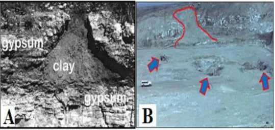
other rocks. Regardless of the form of gypsum, if present, it typically is the most soluble rock or mineral at dam sites. Therefore, unsaturated water can readily attack and dissolve the gypsum and open up karstic passageways to the flow of water. Karst processes can create and or enlarge vugs, joints, sinkholes, or caverns, and also can produce brecciated rock as a result of gypsum dissolution and collapse of overlying rock(s). Once a through-flowing passage is created in the gypsum, enlargement of the opening results from further dissolution and from abrasion, as water-born particles are transported through the cavity. These karstic openings in the rock may stay open, or subsequently may be filled with clay or other sediments deposited from flowing through waters (refer Figure 6A). Such “clay- filled cavities” can be reopened and reactivated as karsts features if water finds a pathway through and erodes the clay filling. Or if the hydrostatic head forces an opening through the clay filling [16]. A site 30km east of Mosul Dam. Clay filled karst in gypsum (Figure 6B). The holes in the floor of the site (a nuclear site called Atshan) are sinkholes which were not visible on surface (1987). The case of Mosul Dam, Iraq, is an extreme case of karst problems and the grave risks it poses. The dam is an earthfall dam, 113m high, 3600m long, which impounds a reservoir of 11.11 Billion m3 of water. It was completed in 1986 after 36 years of investigations and studies. The design, however failed to answer to the required level of safety required for such a large dam which threatens, in case of failure, well over one million people (refer Figure 7 and Figure 8).
Figure 6: A) Gypsum- karst opening, now filled with clay deposited from through-flowing waters. Site is in the impoundment area of the abandoned
Upper Mangum Dam. Image area is 2m wide [16]. B) A site 30km east of Mosul Dam. Clay filled karst in gypsum.
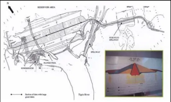
Figure 7: Mosul Main Dam – Layout and cross section.
The source of problems is related to geological factors which are, 1. The karsts prevailing in the dam site and in the reservoir area.
2. The existence of gypsum/anhydrite rock formations in dam foundation alternating with soft marl layers and weathered and cavernous limestone beddings.
3. The presence of an extensive ground water aquifer which affects
considerably the ground water regime in the central part and right bank. Figure 9, shows the extent of the karst’s phenomena in the form of sinkholes upstream area of the dam and in the reservoir.
Figure 9: Sinkholes present in the Reservoir.
The dam foundations itself is very complicated and the combination of gypsum/anhydrite layers with the cavernous limestone gave rise to very favorable conditions for seepage and dissolution environment by the formation of highly developed conduits and caverns for the flow of ground water. The result was extensive dissolution of gypsum and gypsum anhydrite rocks present above and below these limestone layers. These dynamics caused the collapsing of whole layers of clayey marls into the underneath cavities forming beds composed of brecciated gypsum particles and anhydride blocks embedded into a loose clayey matrix as described before and shown in Figure 6. Four such layers were discovered during the geological investigations and were tagged as the (Gypsum-Brecciated) layers (GB0, GB1, GB2, GB3). These layers had thickness, which ranges between 8m and 16m; and were found at different depths, the last one was at depth of 80m below the river bed while the first day lighted in the excavation of the foundation of spillway
chute ski jump on the left abutment of the dam. The GB layers proved to be very important due to their erratic behavior during the grouting of the deep grout curtain under the dam, where the deep this curtain was the main ante- seepage measure adopted in the design of the dam not only to reduce uplift to the safe limits, but, also to reduce the seepage flow under the dam to get saturated condition there and stop the dissolution of gypsum. This assumption was not realized as the GB layers did not accept all sorts of grouting solutions, or when it did these layers could not hold on the grout in the grouted zones and soon deteriorated and grout was washed out with more dissolution. This condition was discovered after river closure and diversion of the flow through the diversion tunnels, which made stopping the job practically impossible. The only way was to establish a continuous repair and maintenance grouting program, which continued from 1986 till mid 2014 with no hope of having any end to it. The quantity used during these years exceeded 95,000 tons of solid grouting materials. Although grouting is considered now as only a temporary remedial solution, while still looking for a permanent one, it is still very important to keep grouting works to increase the life of the project as long as possible and prevent a sudden failure. The grouting works, however, were forced to halt due to the occupation of ISIS to the site on 8th August 2014. The works did not
start immediately after recovering the site ten days later, but as the site was secured later by an American force, a United States Interagency Team led by the USACE engineer`s and specialists started through investigations of the foundation conditions including, settlements, lateral displacements and checking of seepage water quantities and quality to find there was grave deterioration of the grout curtain, increased dissolution of gypsum and loss of material from the foundations.
This work took the whole of 2015, the final report of the findings was issued at the end of that year. By using the Screening Portfolio Risk Analysis (SPRA) procedure, which was developed and used by USACE since 2005 for Dam Safety rating of their portfolio of dams, they concluded that Mosul Dam was the most unsafe dam compared to all of the USACE dams. In fact, it showed that Mosul Dam was in a state of extreme and unprecedented high relative risk when compared to all the dams, which belonged to USACE, and it was on the verge of failure. These findings, and due to the pressures exerted by the US Government on the Iraq Government, a new grouting contract worth $296 million to conduct grouting and maintenance on the dam for a period of 18 months was signed in March 2016 with a foreign firm to restore foundation condition as before 2014. This work was completed on schedule after an extension of time to train the Mosul Dam personnel to continue the work for an indefinite time in the future. It may be concluded that, the karst hazard in this site was not figured out completely, and if the interpretation of the geological conditions during the many investigations campaign was correct, and if the behavior of gypsum and gypsum breccia was properly understood, then the designers should have never relied on the grouting curtain an as ante- seepage measure, but should have used a diaphragm wall. Even a little quantity of seepage through 80% efficient grout curtain was sufficient to cause continued dissolution as saturation condition could not be established.
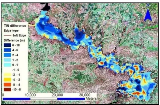
In spite of the repeated repairing and maintenance grouting of the deep grout curtain, it cannot put an end to the karst dissolution at the site around the dam and in the reservoirs. Many sinkholes have formed so far just downstream of the dam which forced the authorities to limit the maximum operational water level to elv. 319m. a.s.l. instead of the maximum designed water level of 330m a.s.l. and so loosing sizable volume of the live storage and the benefits that are obtained from it with it. During the period 2014-2019, Mosul Dam problems and its safety risks became worlds’ news on the media, and several hundred news reports and technical papers were published. Many such papers were written by the author and a technical team from Luleå Technical University of Sweden which give complete technical reviews and analyses of these problems; it is highly recommended to refer three such papers to the reader’s attention for full understanding of this so far unique case of karst hazards in dam’s construction. These papers appear in the references list, [17], [18], [19], [22]. Karst hazards in limestone are not less problematic than those in gypsum karst, as far as dam’s safety and usefulness are concerned. One good example is the case of the Boljunčica reservoir in the Istria peninsula (Croatia).
This reservoir is impounded by the construction of the 35m high Letaj concrete arch dam on Boljunčica River. The dam was completed in 1970, but the filling of the reservoir with water started only in 1973. The reservoir is situated at the contact zone between water impermeable Eocene flysch and deep Eocene and Cretaceous limestone. The bottom of the reservoir is partly covered by both flysch and Quaternary deposits. The water volume of the reservoir at the spillway elevation of 93.00m a.s.l. is about 6.5 x 10⁶m3. This is a multipurpose reservoir, which was built
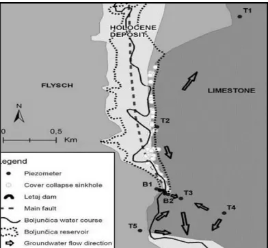
in order to protect the fertile downstream Cepić polje from flood, to store water for irrigation and to control sediment transport. In order to prevent water leakage, a grout curtain was built in the limestone below and around the Letaj dam. The thickness of this grout curtain is about 20m. The main purpose of grout curtains is to change the hydrogeological characteristics (reducing the permeability) of the rock mass. Constructing a grout curtain in a karstic environment with high random distribution of karst features contains some uncertainties and surprises that cannot be excluded. The grout curtain developed around Letaj dam did not protect the reservoir from water losses. Up to 50 covers collapsed sinkholes have been found in the area. They are oriented along the eastern edge of the reservoir at the contact zone of flysch and limestone; their locations are shown in Figure 10.
Figure 10: Map of reservoir with designated geological structure piezometers, cover collapse sinkholes and groundwater flow directions.
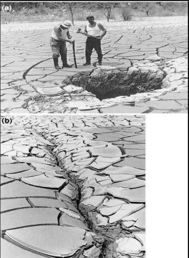
The minimum sinkhole`s elevation is 75m a.s.l., while the maximum reaches 89m a.s.l. The photographs of Figure 11a and 11b show two different shapes of covered collapse sinkholes. It is obvious that they serve as swallow holes, i.e. water quickly flows through them to the karst underground. It should be stressed that after each filling and emptying of the reservoir new covered collapse sinkholes appeared. Two different shapes of covered collapse sinkholes at the bottom of the Boljunčica reservoir are shown in Figure 11.
Figure 11: Photograph of two different shapes of covered collapse sinkholes at the bottom of the Boljunčica reservoir.
This case represents an unsuccessful case of building a reservoir in karst, caused mainly by insufficient geological, hydrogeological and hydrological investigations. Owing to the extreme heterogeneity of the karst underground forms, it is very hard to obtain reliable local information, parameters and conclusions on water circulation processes. It should be stressed that in different karst areas water losses from the reservoirs will become manifest in different ways. Karstification below dam sites and at the reservoir bottoms may increase water losses in the future. This is probably a case of the Boljuncˇica reservoir. The basic problem to recognize and explain the information contained in groundwater data. The best and probably only solution is holistic interdisciplinary cooperation amongst numerous experts [20]. Sinkholes, in addition to causing loss of valuable storage water, can pose an extreme threat to the stability of dams, if the happen to develop very close or in the foundation of such dams. In the case of Mosul Dam this hazard was considered thoroughly. In Potential Failure Mode Analysis (PMPA), the development of sinkholes close (refer back to
Figure 9) or under the dam figured prominently in three Potential Failure modes which are abstracted from a paper entitled “Risk Management Concepts in Dam Safety Evaluation: Mosul Dam as a Case Study” written by the author and a colleague from the Luleå Technical University of Sweden [21]. The following details, taken from Table 6 on page 648 of this paper, are summarized from these PFMs;
Potential Failure Mode N1
Cavity/cavern forms u/s at depth 0-10m below foundation of Mosul Dam in GB1, GB2, GB3 and possible collapse of cavern and connecting directly to reservoir, flow velocity increase leading to increased dissolution and internal erosion. Embankment is compromised by core collapse, loss of upstream shell dam breaches. Adverse conditions are: GB1, GB2 had been repeatedly grouted, sinkholes upstream had developed; blanket grouting does not extend under shells and doubts on the effectiveness of consolidation grouting; dam could fail if erosion starts at the dam/foundation interface. Effect of grout curtain is temporary and needs repeated grouting.
Potential Failure Mode N2
A large 5 to 30m diameter cavern forms u/s at depth 10-60m below foundation of Mosul Dam in GB1 progressing to foundation/dam body interface connecting to the reservoir. Increased inflow into foundation and increased dissolution and wash out of materials, embankment compromised, and collapse of section into cavity and dam breaches: adverse conditions: high grout takes were recorded in GB1, sinkholes upstream had developed; blanket grouting does not extend to this depth and no blanket under u/s and d/s shells, effect of the grout curtain temporary and needs repeated grouting.
N3 Potential Failure Mode
A very large 30 to 40m diameter cavern forms u/s at depth of 60-80m below foundation of Mosul Dam in GB0, and possible collapse progress to the foundation/dam body interface connecting to the reservoir, leading to increased dissolution and internal erosion embankment compromised by loss of critical components and collapse of a dam section and dam breaches. Adverse conditions: GBO unit has 15-20m thickness with repeated high takes grouting; sinkholes have developed u/s and d/s of the dam, with only grouting works in the uncertain deep curtain, there may not be visible warning signs of deterioration until too late, dam section may collapse leading to dam breach.
Construction of dams in the karst region can be very challenging task and requires thorough geological and hydrogeological investigations and the recruitment of expert in these fields.
In the case of Mosul Dam, large volume of geological information was accumulated during the investigations, but it is unfortunate to see that some of the basic facts were not interpreted correctly [22]. This applies to the incorrect correlation of the
encountered beds in the exploration boreholes and miss-understanding of the actual stratigraphic succession at the dam site. This misinterpretation contributed to misleading results regarding the true karst zones, depths and the type of rocks and their thicknesses in the foundation zone and surrounding area. As a result, the dam was placed on problematic foundations consisting of brecciated and highly karstified gypsum/anhydrite rocks and/or conglomerates in which gypsum forms the main constituent as cementing materials. Karstified beds were not recognized in some depths and were described as normal marl and/or breccias. Moreover, Terra Rosa; a good indicator for karst forms was interpreted as “bauxite” [22]. This also added to the use of improper method of foundation treatment by adopting a deep grout curtain as the main anti-seepage measure instead of using a more positive measure by constructing a diaphragm wall [22].
In response to the great number of karst failures and hazards in the previous years, the engineering problems in karst have been the main topic of several conferences and meetings in the last decades that resulted in interesting volumes and special issues. From 1984 to 2011, twelve Multidisciplinary Conferences on Sinkholes and the Engineering and Environmental Impacts of Karst have been organized in the United States and in Europe. Since 2004, problems related to karst environments have been the subject of specific sessions at the General Assembly of the European Geosciences Union within the framework of the Natural Hazards Program. In many cases, the most significant outcomes from these sessions have been published as special issues of peer-reviewed journals or as a book. Notwithstanding these efforts, little attention is given to these issues in karst landscapes, and few regions of the world fully understand or appropriately manage karst areas [23].
4. Hazardous conditions in dam’s foundations
Foundation is a critical structural element in the safety of any dam, which serves two purposes:
1. To provide structural stability and sufficient stiffness to limit deformations to within acceptable behavior patterns under the weight of the dam and the forces acting on it, and to maintain this integrity under the conditions that exist and/or can be expected to develop over time.
2. To control seepage under the dam with respect to flow quantity and quality, uplift pressures, and erosive stresses. If one of these functions is not sufficiently addressed, the dam’s performance may be impaired to the point that the dam is unsafe.
The foundation conditions at any particular site are also a determining factor in the selection of the type of the dam, and its safe operation. In the context of dam safety, the design and supporting geological investigation are important critical controls’ elements that reduce risks. Accordingly, the dam itself is planned, and quality control can be exercised through design and construction specifications, but the foundations’ conditions are determined by nature and are subject to the inherent
heterogeneities and potentially complex conditions, which should be discovered by proper geological investigations. In any meaningful geological investigation of the certain dam site, many questions are to be answered to avoid unpleasant surprises with respect to geologic hazards, during construction or operation. Typical questions are, presence of hazardous geological structure under the dam, faults, their extent and nature, degree of weathering in rock formations under the dam, presences of weak layers, which represent weak shearing plains…etc.
Faults in Dams Foundations
One striking case of undiscovered faulting foundation’s leading to dam failure is Malpasset dam catastrophic failure in France on 2nd December 1959. The dam was a 66-m high thin arch dam situated on the Reyran River 10km upstream of Frejus in the Cannes District, France. The arch was 1.5m thick at the crest and 6.7m thick at the base, refer Figures 12a and 12 b. The right abutment consisted of massive rock, but the left abutment depended on a thrust block protected by a wing wall due to the topography of the site. An overflow spillway, 30 m long and capable of discharging 178m3/s was located in the central portion of the crest [24], [25], [26]. The reservoir had a capacity of 51.4x10⁶m3 at the maximum water surface.
Figure 12b: Cross Section of Malpasset Dam [24].
The foundation was described as a “synclinal carboniferous zone enclosed by the metamorphic horizons of the base Massif of the Esterel”. Exposed at the surface and in the investigation tunnel, were numerous stratified mica schist layers, which could be crumbled with bare hands. A fault zone was present in the left abutment, unidentified until after the failure, refer Figure 13. The foundation contact was grouted with blanket holes to a depth of about 5m. A grout curtain was not considered necessary due to the low permeability of the rock below the 5m depth. No drainage had been provided in the dam or foundation, and no instrumentation, other than surface measurement point was installed.
After the failure, the flow of water has cleaned the slopes perfectly from any loose or even weathered material, the rock mass structure appeared very heterogeneous and crisscrossed by joints at all scales and in any direction. Only the failure daylighted two features of the rock mass which proved instrumental. A huge block of foundation rock was missing at the left half of the dam arch, leaving an excavation in a dihedral form limited by two sub plane faces, as visible in Figure 14. The downstream face is a true fault plane with a thin cover of crushed rock (fresh scratches on the surface proved the whole block had moved upwards). Its upstream face looks like a set of tears along two or more foliation surfaces, without any crushed rock. Neither the fault nor the foliation had been recognized before, but it strikes perpendicular to the valley axis and its dip is about 45° upstream would have considered it as perfectly neutral with respect to the thrusts
received from the dam; the continuity of rock foliation had not appeared either, within the so heterogeneous structure of the gneiss. So, a geometrical trap was in place, waiting for a force susceptible to move the block, which will appear later. The cleaning action of the flow made the fault path visible on the right bank and daylighted its cross section at either bank toe, refer Figure 15.
Figure 14-Top: the “dihedral” excavation with half of the thrust block fallen after the flow. Bottom: a wide crevice is open just upstream of the concrete
arch, wider at the base and closing more higher [24].
Figure 15: Close view of a cross section of the main fault on right bank. The finely crushed borders of the fault zone are well visible.
Post-failure review uncovered no problems of the arch structure. The design and construction of the dam were well-executed and in accordance with current standards. Material tests and trial load analysis indicated the dam structure could easily withstand loads associated with the reservoir filling. Further investigation, however, determined that the failure resulted from particular attributes of the foundation material and the geologic structure (discontinuities) that were not recognized. All measured movements and post- failure evidence pointed; however, to sliding on the fault as the cause of failure.
After thorough investigation of all factors, it is believed that the failure was indeed caused by sliding on the upstream dipping fault plane. Large uplift forces developed on the upstream foliation shear; for one of the several reasons or a combination of reasons:
1. The stresses generated in the rock extended to great depths, decreasing the rock permeability and forming an underground dam.
2. Tensile and shear stresses at the upstream face opened the foliation shear planes and allowed water pressures to easily penetrate to great depths, or 3. Clayey materials along the foliation shear plane created a natural dam in
the foundation.
As the reservoir water rose, the loading increased until the block began to move. The arch tried to redistribute the loads higher to the thrust block, but under the extreme overload, the thrust block moved about 0.8m downstream separating from the attached wing (foot) wall. Without any place to transfer the load, the entire left side of the dam lifted and rotated downstream (all the while the hydraulic forces are increasing) until the dam ruptured. Professor Carl Terzaghi commented upon the Malpasset failure in February 1962 as follows:
“The left abutment of this dam appears to have failed by sliding along a continuous seam of weak material covering a large area. A conventional site exploration, including careful examination of the rock outcrops and the recovery of cores from 2-inch boreholes by a competent driller, would show - and very likely has shown - that the rock contained numerous joints, some of which are open or filled with clay.”, he adds;
“From these data, an experienced and conservative engineer-geologist could have drawn the conclusion that the site is a potentially dangerous one, but he could not have made any positive statement concerning the location of the surface of least resistance in the rock and the magnitude of the resistance against sliding along such a surface...” The development of the failure process may be better understood with the help of Prof Paul G. Marinos visualization shown in Figure 16 and Figure 17 [27].
Figure 16: Malpasset Dam Geological Model [26].
5. Dams on hazardous weathered foundations
It is normal for dams’ designers to look for the best possible geological conditions in any proposed site subject to other factors such as topography, construction materials availability and economic considerations. The selection of type of a proposed dam, however, is controlled mainly by the foundation condition(s) at the selected site as a primary factor. Generally, gravity dams require sound rock foundation, which may be reached after excavating and removing of fewer competent and unconsolidated layers to reach solid rocks, while arch dams need, in addition, good and massive rock abutments which often do not improve with distance excavated into the sides of the valley. Except for low dams of small gross weight, concrete dams are not built on unconsolidated deposits because of their low bearing strength. Larger dams constructed in whole or in part on unconsolidated deposits should without exception, be earth or rockfill dams with the capacity to adjust to settlement in the foundation materials. Dam safety in all cases must be insured, and if it is economically feasible, all hazardous material under the base of a proposed dam, which could cause excessive settlement and leakage, should be removed. If this cannot be done, the dam design should be modified to consider such material. Sometimes it may be necessary to remove material to considerable depths, or scale of loose masses of rocks on the abutments and in such cases, it rests with the engineering geologist to determine the expected depth of weathered or unsound rock or overburden that must be removed in advance of construction. If it is not feasible to remove all of the weathered unconsolidated materials, and in order to eliminate their hazards, the design may include some or all of the following measures;
a) Excavating and removing all low-quality materials for the purpose of preparing of a clean surface that will provide optimum contact with the dam materials, whether earth fill or concrete, to be placed on that surface. Therefore, excavations in bedrock should extend into firm, fresh rock. Any closely fractured zones extending downward, especially if containing soft altered materials such as clay gouge or other products of weathering, should be removed if feasible. For earth fill dams’ cutoff trench may be excavated down into bed rock and filled with the same core material of the dam without the need to remove the material from the remaining part of the dam base, where scarifying the surface may suffice. Prolonged exposure of both earth and rock foundations to the atmosphere or to water frequently results in deterioration by hydration, dehydration, frost action, shrinkage, and expansion with changes in temperature. It is a good practice to protect reactive surfaces that will be exposed for long periods of time with bituminous materials or plastic sheeting, alternatively; original cover is not removed until final cleanup and just prior to placement of the dam.
b) Poor foundation conditions in bed rock formations are associated with close fracturing, weathering or hydrothermal alteration, or poorly indurated sedimentary rocks; therefore, treatment by dental concrete and blanket
![Figure 2: View of the Vajont reservoir after the landslide (1963) [4].](https://thumb-eu.123doks.com/thumbv2/5dokorg/4427111.106510/5.813.159.658.436.794/figure-view-the-vajont-reservoir-after-the-landslide.webp)
![Figure 5: Karst features characterized by sinkholes, caves, and underground drainage systems [12]](https://thumb-eu.123doks.com/thumbv2/5dokorg/4427111.106510/14.813.171.644.106.450/figure-karst-features-characterized-sinkholes-underground-drainage-systems.webp)
![Figure 12a: Plan of Malpasset Dam [24].](https://thumb-eu.123doks.com/thumbv2/5dokorg/4427111.106510/25.813.191.624.501.774/figure-a-plan-of-malpasset-dam.webp)
