http://www.diva-portal.org
This is the published version of a paper published in ADV MATER SCI ENG.
Citation for the original published paper (version of record): Sadeghi, M., Mahmoudi, J. (2012)
Experimental and Theoretical Studies on the Effect of Die Temperature on the Quality of the Products in High-Pressure Die-Casting Process.
ADV MATER SCI ENG, (434605)
http://dx.doi.org/10.1155/2012/434605
Access to the published version may require subscription. N.B. When citing this work, cite the original published paper.
Permanent link to this version:
Experimental and theoretical studies on the effect of die temperature on quality of the products in high pressure die casting process
Mohammad Sadeghi1,a, Jafar Mahmoudi1,b 1
HST Department, MÄLARDALEN University, Sweden, a mohammad.sadeghi@mdh.se b
jafar.mahmoudi@mdh.se
Journal of Advances in Materials Science and Engineering Volume 2012, Article ID 434605, 9 pages
Abstract: In this work, die temperature in high pressure die-casting of A380 alloy is optimized by experimental observation and numerical simulation. Ladder Frame (one part of the new motor EF7) with a very complicated geometry was chosen as an experimental sample. Die temperature and melt temperature were examined to produce a sound part. Die temperatures at the initial step and final filling positions were measured and the difference between these values was calculated. ProCAST software was used to simulate the fluid flow and solidification step of the part and the results were verified by experimental measurements. It is shown that the proper die temperature for this alloy is above 200 oC.
Keywords: High pressure die casting, Die temperature, Defects, Over flow, A380 alloy,
Simulation
1. Introduction
High pressure die casting (HPDC) process has been widely used to manufacture a large variety of products with high dimensional accuracy and productivities. It has a much faster production rate in comparison to other methods and it is an economical and efficient method for producing components with low surface roughness and high dimensional accuracy. All major aluminum automotive components can be processed with this technology [1-7]. In this process, the metal is injected into the die at high speeds (30–100 m/s) and typically 40–60 m/s for aluminum alloys [2]) and under high pressure through complex gate and runner systems [3].
Although HPDC has a considerably higher speed than other metal forming processes, due to complexity of the process and the number of variables, optimization of the process is essential. In particular, there are issues related to control of die temperature, solidification of the components, quality control of the castings, and more important, development or use of a
coherent and integrated system. The mechanical properties of a die-cast product are principally related to the die temperature, the metal velocity at the gate, and the applied casting pressure [4]. Combination of die temperature, fluidity of the molten metal, geometrical complexity of the parts and cooling rate during die casting affect the integrity of a cast component. If these parameters are not adequately controlled, various defects within the finished component will be expected [6, 7]. Thermal profile of the die during operation is another important factor in the production of high quality components. Too high temperature of the die will lead to longer solidification which consequently prolongs the cycle time, while a cold die will contribute to a number of surface defects [3, 8 and 9].
Kermanpur et al. [14] used FLOW-3D software to simulate the filling and solidification sequences of two automotive components. They process the appropriateness of the running and feeding systems. Schneiderbauer et al. [12] investigated the flow of molten metal in the die cavity threefoldly: a) analytically b) experimentally c) numerically. They studied the effect of flow condition on casting defects. Pereira et al. [13] used Procast software to simulate HPDC process. They studied the effect of the die temperature and melt temperature die life. Rai et al. [11] worked on optimization of main process parameters in HPDC namely die temperature, melt temperature and plunger velocity. Some other investigators have also worked on optimization of process parameters on die-casting by simulation [15-17]. However in many of these works, the geometry of the part is simple and there are few research on very complex part in industry. The aim of this work is optimization of process parameters in die-casting of a complex automotive component named Ladder frame by simulation.
2. Governing equations
In order to perform the mould filling and solidification simulation of automotive part, the commercial finite element code ProCAST was used. Within the framework of an Euclidian description, this software is capable of solving simultaneously three-dimensional transient
thermal and fluid flow problems with free surface. The set of partial differential equations to be solved is briefly summarized below:
• Mass balance
where (N/m2) and (m/s) are the volumetric mass and the velocity of the fluid, respectively. • Momentum balance
where (m/s2) is the gravitation vector, (N/m2) the fluid pressure, and the viscous stress tensor.
• Energy balance, written as an enthalpy formulation
In this equation, (J) is a volumetric heat source that account for mechanically induced dissipation effects, T is the temperature, is the thermal conductivity of the medium and is its specific enthalpy. Please note that entire enthalpy is transported with the velocity of the fluid. In order to account for solidification, ρh is written as follows:
where cp and L are the specific heat and latent heat of fusion, respectively, and fs is the volume
fraction of the solid.
• Free surface modeling, achieved with a scalar variable, Φ, describing the local volume
fraction of the fluid (i.e. Φ = 0/1 if the ‘point’ is empty/full of SSM). Previous balance equations are averaged with this variable, which is adverted according to:
0
)
(
=
+
∂
∂
v
div
t
ρ
ρ
ρ vg
div
p
grad
v
v
div
v
t
vρ
σ
ρ
ρ
+
⊗
=
−
+
+
∂
∂
)
(
)
(
)
(
g pσ
v mechQ
gradT
k
div
hv
div
h
t
+
=
+
∂
∂
)
.
(
)
(
)
(
ρ
ρ
mechQ
k
h)
1
(
)
(
0∫
+
−
=
T s pd
L
f
c
h
ρ
θ
θ
ρ
ρ
These equations need to be explained in the frame work of the paper. 3. Modeling procedure
A 3-dimensional model of the cast product is an important input for design and analysis functions in PROCAST, and can be imported through a data exchange interface using the industry standard parasolid format (Fig. 1). The material properties of the alloy was extracted from the software database and are shown in table 1.
Fig.1: Geometry of Ladder Frame product
Table. 1: Material Properties
Solidus temperature 595 [°C] Liquidus temperature 521 [°C] Specific heat 1.13044 [kJ/kg/K]
0
.
Φ
=
+
Φ
∂
∂
grad
v
t
Density 2480 [kg/m3] Conductivity 100.4832 [W/m/K]
Latent heat 218.644 [kJ/kg]
Solid fraction According to Scheil equation
In order to evaluate the effect of process parameters on the filling pattern and quality of the final product, three main process parameters were varied during simulation and their effects on the results were studied. Initial and boundary conditions used in the simulation are given in table 2. To ensure mesh independency of the results, two deferent mesh sizes were used and simulation results were compared at these two mesh sizes.
Table.2 : Initial and Boundary Conditions
Ram velocity 2-4 m/s
Die temperature 150 , 200 & 250 oC Melt temperature 670 , 680 , 690 oC Heat transfer coefficient 9000 w/ m^2.K [10] Number of Finite Element Meshes 521380
4. Experimental procedures
The material used in this study was A380 material. Die temperatures were 150oC, 200oC and 250oC. Initial melt temperature of 680oC, shot sleeve speed of 3 m/s and speed melt in gate of 55
m/s for the Ladder frame were assumed. Measurement of the melt temperature was carried out by thermocouple and LASER pyrometer (model chy 110) at the die surface.
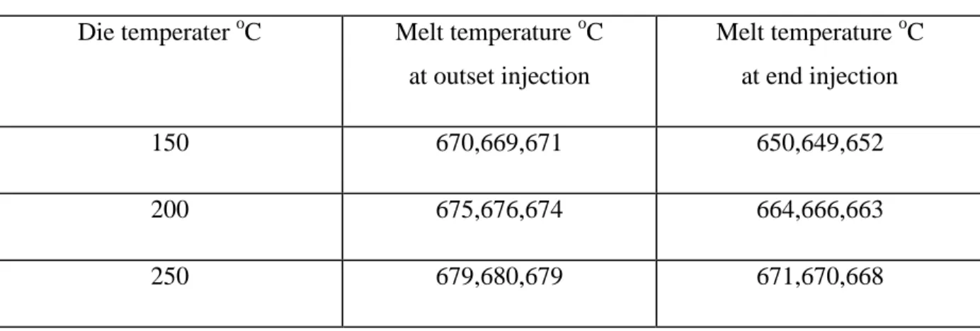
Melt temperature was measured at the die entrance at the start of injection and at the end of filling. This test was done at the various die temperatures. The IDRA1600 die cast machine was used for injection. Test results are illustrated in tables 3 and Fig. 2- 4.
Table 3 : Melt temperature at outset injection in shot sleeve and at end injection final filling position filling position
Die temperater oC Melt temperature oC at outset injection Melt temperature oC at end injection 150 670,669,671 650,649,652 200 675,676,674 664,666,663 250 679,680,679 671,670,668
The variations of melt temperature versus die temperature in different cases are shown in Fig.2. The results show that the die temperature varies from 150 to 250 °C, while the melt temperature varies between 660°C and 680°C.
Fig.3. Melt temperatures at the end of the die and end injection versus die temperatures.
Fig.4. Reduction of melt temperature at various die temperatures at the initial and the end of injection.
Fig.5 shows typical examples of cold flow surface defects in pieces produced in a die with temperature of 150oC (Figs.1-3). As can be seen from this figure, cold shot defects occur at final filling positions predicted by the software.
Fig.5.Cold flow surface defects at final filling positions
This kind of defect occurs because the melt has to move a long way in the die cavity and finally it reaches to its liquidous temperature. If the metal is partially solidified when two flows come together, the laps are formed and laminations as the characteristic of surface defects appear. This defect is often apparent at the end of the flow pattern especially when the die is colder. Overflows were added in these positions to eliminate these kinds of defects (Fig. 6).
Fig. 6: positions of added overflows to the mold
Gas porosities caused by entrapped air during metal injection are illustrated in Fig.7. Porosity caused by turbulent flow, low die temperature and long flow path in combination with a thin wall section. An example of turbulent flow pattern of the melt at three holes in front of the gate is shown in figure 8a. these holes cause agitation in the flow pattern. This agitation can result in air entrapment and oxidation and also they can change the flow pattern of the molten metal to more turbulent one and cause branch like flow. By eliminating these three holes in the model (Fig. 8b), more stable flow pattern was observed. Some other possible sites of air entrapment are shown in figure 8d. These sites have been generated as a result of complex and branch-like flow pattern in the mold.
a)
b)
Fig. 8: Velocity vectors of the melt at the three holes in the front of the gate
5. Simulations Results
The boundary conditions implemented in the software are shown in Table.2. Then, the model was run for die temperatures of 150
o
C, 200
o
C and 250
o
C while other parameters kept constant. The flow pattern of the melt in the die at 200
o
a) b) c)
d)
e) f) g)
Fig.9. Steps filled die by the melt and show End points
Temperature distribution of the melt in two different die temperatures at equal time are compared in Fig.10. In the case of 150 oC die temperature, melt temperature falls down near the liquidous temperature of the material and there is danger of cold shot flow in this case.
a2 b2
a3 b3
Fig.10. Flow pattern of melt with die temperature a) 150 oC and b) 250 oC in same time Time a1=b1, a2=b2 and a3=b3
Fig.11. shows the final solidification positions at the end of casting. Shrinkage defects occurred at the final solidification positions are shown in Fig. 12. In this figure, one can see a comparison between simulation results and experimental observation at those areas. The outer side of the part has shrinkage defects which were predicted by the software. The verified model interestingly represented the correct location of the porosity defects in the castings.
Fig.11. Hot spots at the end of solidification step; which are susceptible to casting defects.
Fig. 12: Defects occurred in final solidification positions
6. Discussion
The difference of two melt temperature curves at the initial and end of the process at 250 oC, 200
o
C and 150oC are 9.5 oC, 10 oC and 19.5oC, respectively (Fig 3). It is seen that there is a break point in the curve of end injection at die temperature of 200oC. Therefore, defects are more probable at die temperatures less than 200oC. These results are supported by experimental observations. With regard to this break point, it can be seen that the normal die temperature for this alloy is 200oC. Maximum temperature depends on the die cooling system and optimized cycle time for production of a specific part.
Filling pattern of the melt is shown in Fig.6. Final filling positions in the die are illustrated in this figure. Same thing was observed at the die temperature of 150oC (Figs. 1-3). Filled Percentages of mold at two die temperatures of 150 oC and 250oC are shown in Fig.5. By comparing result at equal time steps, filled percentage of die at the die temperature of 250oC is more than that of 150oC.
Figures 11 and 12 show the results of solidification simulation. In this figure, it is seen that the peripheral area of the part is at the liquid phase while other areas are solidified. Therefore, these areas are susceptible to formation of shrinkage porosities. In order to reduce the cold flow defects and air porosities, overflows can be placed near these areas in the die design.
7. Conclusions
-- Comparison of the experimental and simulation results indicates that defects in the pieces are placed at the predicted places by simulation.
-- Optimum die temperature for A380 alloy for H13 die material is around 200 oC.
-- If the die temperature is reduce from the optimum temperature range, probability of cold flow defects and air porosities increase.
-- Determination of optimized places of overflows by simulation led to decrease of some casting defects such as cold shots and air porosities.
8. Reference
1- Dargusch, M.S., Dour, G., Schauer, N., Dinnis, C.M., Savage, G.,’The influence of pressure during solidification of high pressure die cast aluminum telecommunications components,J. Mater. Process. Technol., 2006, vol. 180, pp.37–43.
2- Z.W. Chen, M.Z. Jahedi.,Die erosion and its effect on soldering formation in high pressure die casting of aluminum alloys,Materials and Design ,1999, vol.20,pp.303-309. 3- P.W. Cleary , J. Ha , M. Prakash , T. Nguyen,3D SPH flow predictions and validation for high pressure die casting of automotive components,Applied Mathematical Modeling ,2006, vol.30, pp. 1406–1427.
4- Laws, K.J., Gun, B., Ferry, M.,Effect of die-casting parameters on the production of high quality bulk metallic glass samples,Mater. Sci. Eng. , 2006, A425, pp.114–120.
5- D. McBride, T.N. Croft, M. Cross,A coupled finite volume method for the computational modeling of mould filling in very complex geometries,Computers & Fluids ,2008, 37, pp. 170–180.
6- C.C. Tai, J.C. Lin ,The optimal position for the injection gate of a die-casting die, Journal of Materials Processing Technology ,1999, vol 86, pp. 87–100.
7- S.W. Youn, C.G. Kangb, P.K. Seo,Thermal fluid/solidification analysis of automobile part by horizontal squeeze casting process and experimental evaluation,Journal of Materials Processing Technology ,2004, vol.146, pp.294–302.
8- J.X. Zhou, L.L. Chen, D.M. Liao, R.X. Liu,High pressure dies casting module of InteCAST software and its applications,Journal of Materials Processing Technology ,2007,pp. 192-193 and 249–254.
9- Shuhua Yue, Guoxiang Wang, Fei Yin, Yixin Wang, Jiangbo Yang,Application of an integrated CAD/CAE/CAM system for die casting dies,Journal of Materials Processing Technology ,2003, vol.139, pp. 465–468.
10- J. P. Papai,”Contact heat transfer coefficients in aluminum alloy die casting: An experimental and numerical investigation,PhD thesis, the Ohio state university, 1994 pp.70. 11- Jitender K. Rai, Amir M. Lajimi, Paul Xirouchakis, “An intelligent system for predicting HPDC process variables in interactive environment” journal of materials processing technology, 203, 2008, 72–79.
12- S Schneiderbauer1, S Pirker1, C Chimani2 and R Kretz” Studies on Flow Characteristics at High-Pressure Die-Casting” The 3rd International Conference on Advances in Solidification Processes.
13- M F V T Pereira, M Williams and W B du Preez, “REDUCING NON VALUE ADDING ALUMINIUM ALLOY IN PRODUCTION OF PARTS THROUGH HIGH PRESSURE DIE CASTING” Light Metals Conference 2010.
14- A. Kermanpur, Sh. Mahmoudi, A. Hajipour, “Numerical simulation of metal flow and solidification in the multi-cavity casting moulds of automotive components”, J. Mater. Pro. Tech. Vol. 206 (2008), pp62-68.
15- B.S. Sung, I.S. Kim “The molding analysis of automobile parts using the die-casting system” J. Mater. Pro. Tech. Vol. 201 (2008), pp635–639.
Die Casting 9-10 April 2008, Montichiari Italy.
17- Z. Brown, C. Barnes, J. Bigelow - Contech U.S., Kalamazoo “Squeeze cast automotive applications and design considerations”, 4Th International Conference High Tech Die Casting 9-10 April 2008, Montichiari, Italy.