Design of controller board for a
Lunar Rover
Electronic Basic Thesis
Marcos Rejas Haddioui
Mälardalens University
School of Innovation, Design and Engineering
Supervisors: Lars Asplund, Giacomo Spampinato
Abstract
The Lunar Rover (Roony) is a robotic project group at Mälardalens University composed by students. The objective of this group is to design and build an autonomous robot that has to be able to move by itself through the moon terrain.
The Lunar Rover is divided in several sub-projects from different knowledge areas; the objective of this electronic thesis is to design a controller board. The designed board will be able to connect the robot to an external dispositive (via JTAG, or WIFI), and also it will control and connect the different robot’s peripherals.
The main component of the controller board is the microcontroller AT90CAN128.
The peripherals are a steeper motor, a LIDAR system (Light Detection And Ranging), a WIFI chip(WIPORT™), a bus can driver, an accelerometer, a LIPO( Lithium-Ion Polymer) battery charger, a Solar photovoltaic cell handler, and sixteen DC motors(four in each leg of the robot).
Once the logic design has finished, the PCB design is done attending the size limitations of the robot. Once the design has finished, a prototype has been built and tested using ATMEL software.
Preface
I dedicate this work, to my family, especially to my parents, because they have been supporting me, and they gave me the chance to come here.
TABLE OF CONTENTS
1 INTRODUCTION... 1
1.1 Background... 1
1.2 Objective and Limitations... 2
1.3 Software ... 3
2.HARDWARE DESIGN ... 4
2.1 Component search ... 4
2.2 Schematic design ... 7
2.2.1 STEP DOWN CIRCUIT... 8
2.2.2 ACCELEROMETER... 8
2.2.3 STEEPER MOTOR DRIVER ... 8
2.2.4 WIPORT... 9 2.2.5 CAN DRIVER ... 9 2.2.6 AT90CAN128 ... 9 2.2.7 BATTERY CHARGER ... 9 2.3 LAYOUT DESIGN ... 10 3. RESULTS... 11
4.CONCLUSSIONS AND FUTURE WORK ... 12
5.REFERENCES... 13
1
1 Introduction
1.1 Background
The Lunar Rover, named Roony (ROver moON ), is a robotic project carried by Mälardalens University, the design started on 2009, the main purpose is to design an autonomous robot that is capable to move though the moon terrain, transport a 5 kg package, be controlled via radio, move at least 500 meters, and survive one Moon day (equals to 14 Earth days).
The Robot is divided in several sub-projects according to the different knowledge areas: electronics, mechanics, computer science and artificial vision.
This controller board is for the second prototype of the Lunar Rover, a first prototype was built in 2009 and it was presented on May 2005 at
Mälardalens University.
Figure 1: First Roony prototype
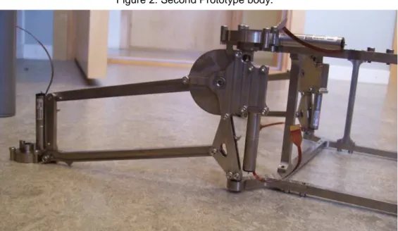
After this first prototype, a second prototype is designed. It has the same body concept but it is milled in titanium, it has also new wheels and brushless motors instead of DC motors. Once the second prototype structure is built, new functionalities were added to the robot, as: -Wireless connectivity.
802.11b/g connectivity via WIPORT -LIDAR system.
Light Detection and Ranging system. It is connected to the microcontroller via Serial port.
2 -Steeper motor.
The controller board must have a driver. -JTAG connectivity.
It is included for programming the microcontroller. -Solar photovoltaic cells.
The power source consists of 22 solar cells, which can supply 100mA at 7.2v. The sizes are 100x290mm.
-Accelerometer.
Dual axis accelerometer. -CAN connectivity.
The robot uses CAN bus for connecting the controller board to the each one of the sixteen boards which control the motors; and also for
connecting the controller board to an external device. -LiPo battery(Lithium Polymer).
Two cell LiPo battery -New motor control boards.
Instead of having the boards in the body, this second prototype has one board for each motor; the boards are located in the legs.
Figure 2: Second Prototype body.
3
1.2 Objective and Limitations
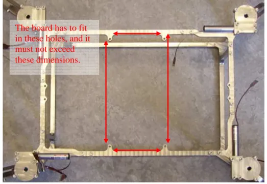
The objective of the thesis work is to design a fully functional controlled board with the requisites described before, and some limitations imposed. There is a size limitation for the board, it has to fit in the space designated to place the controller board.
Figure 4: Controller board slot place.
The distance between holes is 82 mm width per 162 mm length, but the board can be up to 100 mm width per 190 mm length.
There are some other limitations related to the layout design, the controller board must be single sided, and it has two routing layers: top and bottom. Other limitations are applied to the components chose. Both AT90CAN128 and WIPORT have to be used.
The robot will take energy from the solar cells, from 22 solar flexible cells, with 7.2volt nominal and 100mA each one. They will be installed in a mix Series-Parallel, so the supply conditions will be 14.4 volt and 1,1 A.
1.3 Software
The software used to design the controller board is the National Instruments Circuit Design Suite 10.1. In this suite there are two software tools that we used, MultiSim and Ultiboard. The first tool is used to create schematic designs and simulate them, but in this case we only use it for creating the controller board schematic. The second tool is a layout editor.
Multisim has many component libraries and it has also the possibility to create new parts if one component is not found in the libraries.
The board has to fit in these holes, and it must not exceed these dimensions.
4 Also, if a PCB footprint is not found at Ultiboard component libraries, it can be created in an easy way.
Once the schematic design is finished in MultiSim, it is transferred to Ultiboard where the PCB layout will be created.
2. Hardware design
2.1 Component search
Once the robot features have been studied, the first step is to search for the most suitable components according to the needs and restrictions. A brief summary for the most important components are the following:
AT90CAN128
Using the AT90CAN128 microcontroller is not a choice, it is a component restriction, however that restriction does not limit the functionality of the controller board, because of the AT90CAN128 powerful features.
The AT90CAN128 is a high performance, low power 8-bit microcontroller; the main features that we need to use are the following:
-RISC architecture. -16 MHz
-128 KB Flash memory. -4 KB EEPROM memory. -4 KB internal SRAM memory. -JTAG interface
-CAN controller -4 Timer/Counter
-10 bit resolution Analog to Digital converter. -2 USART
-53 programmable I/O lines.
-64 pin Thin Quad Flat Pack (TQFP)
Full characteristics can be found in the datasheet at ATMEL webpage. MCP73862
This microchip is the LiPo battery charger. As the robot has a LiPo battery, a specific battery charger is needed in order to apply an adequate battery charging cycle.
The most important features are the following: -Programmable charge current.
-Programmable safety charge timers. -8.2v voltage regulation.
-Fault and charge output line. -Automatic end of charge control. -Thermal regulation.
5 -16 pin SOIC package.
Full characteristics can be found in the datasheet at MicroChip webpage.
MCP2551
High Speed Can Transceiver. The communication between the controller board and each leg is done via bus CAN. This bus is used also to communicate the controller board and an optional external dispositive.
The main features are the following: -Supports 1Mb/s operation
-Suitable for 12v and 24v systems. -External controlled slope.
-High noise immunity. -8 pin SOIC package.
Full characteristics can be found in the datasheet at MicroChip webpage.
ADXL203
The ADXL203 is a high precision, low power Dual axis accelerometer. It can measure a ±1.7 g acceleration both static (i.e. gravity) and dynamic (i.e. vibration).
The most important characteristics are the following: -1 mg resolution at 60Hz.
-Low power 700uA at 5v.
-X and Y axis aligned to within 0.1º.
-Bandwidth adjustment with a single capacitor. -8 pad LCC package.
Full characteristics can be found in the datasheet at Analog Devices webpage.
L6219
This microchip is Stepper Motor Driver. This controller board must have a stepper motor driver.
The main features are the following:
-Ability to drive both windings of bipolar steeper motor. -Output current up to 750 mA.
-Wide voltage range.
-Half-step, full-step, and micro stepping mode.
Full characteristics can be found in the datasheet at STMicroelectronics webpage.
6
WIPORT
Embedded Wireless Device Server. In order to provide WIFI (802.11b/g) connectivity to the robot, a WIFI chip is included. The use of a WIPORT chip is a requirement.
The main features are the following: -802.11g support
-Serial to 802.11g conversion. -Dual serial port.
-Easy configuration through a web interface. -Ethernet connectivity.
-11 GPIO pins.
Full characteristics can be found in the datasheet at Lantronix webpage.
LM3578A
Switching regulator. It can be set up for buck, boost, buck-boost or inverting configuration.
The most important features are the following: -Feedback input.
-Supply voltage from 2 to 40 volt. -Output current up to 750 mA.
-Current limit and thermal shut down. -8 pin SOIC package.
Full characteristics can be found in the datasheet at National Semiconductor webpage.
TC54
Voltage detector. This voltage detector is used for measuring the voltage level on each battery cell, in order to prevent a deeply depleted cell.
The most important features are the following: -±2% detection threshold.
-Low current drain -SOT23 package.
Full characteristics can be found in the datasheet at Microchip webpage. DIP051A72
Reed relay. It is used to cut the battery-robot circuit. -DIP package
-4.25 KVDC breakdown.
7
2.2 Schematic design
Once the most suitable components are found, we start to design the
schematic circuit. It is very important to follow the design instructions that are in the corresponding datasheets.
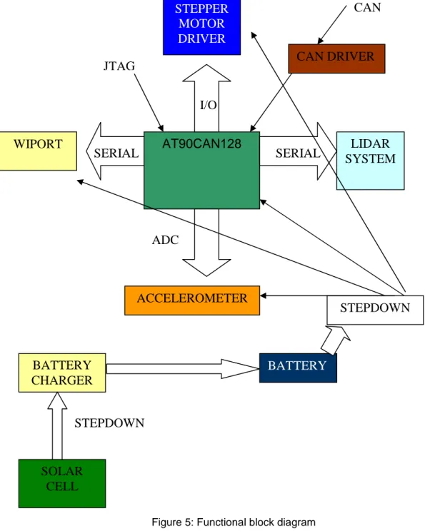
AT90CAN128 LIDAR SYSTEM WIPORT STEPPER MOTOR DRIVER BATTERY CHARGER SOLAR CELL ACCELEROMETER SERIAL I/O SERIAL ADC CAN DRIVER JTAG STEPDOWN BATTERY STEPDOWN CAN
8 In order to provide a clear vision of the circuit we are going to divide it in
functional blocks.
2.2.1 STEP DOWN CIRCUIT
We have to provide three different voltage levels: 3.3 volt for Wiport chip; 5 volt for the AT90CAN128, MCP2551, ADXL203, L6219; and 9,5 volt for the battery charger. The solar cells supply from 0 to 14.4 volt, we use the switching
regulator LM3578A in buck configuration in order to step down the voltage to the 9.5 volt needed by the battery charger (MCP73862). The 3.3 and 5 volt level are provided by another two LM3578A in buck configuration also, they are steeping down from the battery voltage level which from 6.0 to 8.2 volt.
Figure 6: Step-down block diagram
For obtaining the voltage needed, we proceed to follow the datasheet
instructions and the additional components (diodes, resistors, capacitors and coils) are calculated.
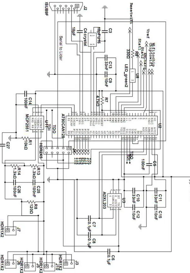
2.2.2 ACCELEROMETER
One requirement is to measure the robot acceleration (G-force). We use the ADXL203, with 5 volt supply voltage this microchip only needs three external capacitors, one of them is a decoupling capacitor, and the other two are used to set up the bandwidth, these two capacitors have a 0,1 uF value, therefore the bandwidth is 50 Hz.
The connexion between the accelerometer with the microcontroller is done via the ADC port.
2.2.3 STEPPER MOTOR DRIVER
The circuit is designed following the datasheet rules, external component are needed, like resistors and capacitors. Driver control is done from the
microcontroller via 7 lines: 6 GPIO and 1 PWM line. Solar Cell 0-14,4V Battery charger 9,5v Battery 6 - 8.2 v 3,3 volt 5 volt
9
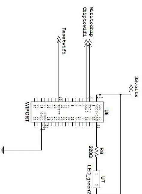
2.2.4 WIPORT
The wireless chip has a supply voltage of 3,3 volts. Only serial port pins are used, TXD and RXD, in order to connect the Wiport chip with the
microcontroller. Also we placed an enable signal and WLAN activity LED.
2.2.5 CAN DRIVER
This CAN bus transceiver needs external components, like decoupling
capacitors and slope control. It is connected to microcontroller pins, TXCAN and RXCAN.
2.2.6 AT90CAN128
Special attention should be paid in this microchip, because is the most
important part of the controller board. Decoupling capacitors are very important in order to increase the noise immunity, such decoupling capacitors should be placed in each supply pin. Other external component needed is the crystal, a 16 MHz crystal is placed with two 18pF capacitors.
2.2.7 BATTERY CHARGER
For obtaining a fully adjustable charger, some components should be added. Vset should be connected to Vdd to obtain an 8.2 volt regulation. Cell
temperature sensor input (THERM) is disabling by connecting this pin to
THREF/3. A decoupling capacitor is needed, and one more capacitor is needed for programming the safety timer. The charger has an enable pin, which is connected to an I/O from the AT90CAN128, and two status pins that are also connected with micro.
10
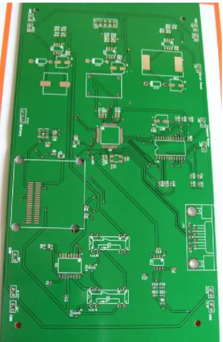
2.3 LAYOUT DESIGN
Once the schematic design has finished, the Layout design is started.
If any PCB footprint is not at Ultiboard libraries, it can be created with the PCB footprint editor.
When we have the entire PCB footprint, the next step is to place the
components in the board. All decoupling capacitors should be placed as near as possible to their corresponding part. If we placed the components in the correct way the routing process will be easier, so it is very important to allocate all the components in the correct position. Other consideration that we should pay attention is heat generation, i.e. a component that generates a great amount of heat should not be placed near temperature sensible components.
The connectors are placed in the board edge, because it will be easier the wiring process.
After placing the components, we started with routing process; first we draw the power nets, which are wider than the normal ones.
11
3. Results
12
4.Conclussions and future work
The controlled board has been designed, but as we did not have enough time to build it, so a possible future work is to build the controller board, to weld the components, and test it in order to ensure a correct working mode. Also it should be connected to the different robot peripherals and check if they work in the properly way.
When everything is checked, the controller board will mounted on the robot with all the features.
13
5.References
http://www.robotik.se/Roony AT90CAN128 datasheet: http://www.atmel.com/dyn/resources/prod_documents/doc7679.pdf MCP73862 datasheet: http://ww1.microchip.com/downloads/en/DeviceDoc/21893d.pdf MCP2551 datasheet: http://ww1.microchip.com/downloads/en/DeviceDoc/21667E.pdf ADXL203 datasheet: http://www.analog.com/static/imported-files/data_sheets/ADXL103_203.pdf L6219 datasheet: http://www.st.com/stonline/products/literature/ds/1377/l6219.pdf WIPORT datasheet: http://www.lantronix.com/pdf/WiPort_IG.pdf LM3578A datasheet: http://www.national.com/ds/LM/LM2578A.pdf TC54 datasheet: http://ww1.microchip.com/downloads/en/DeviceDoc/21434h.pdf DIP051A72 http://www.meder.com/fileadmin/products/en_datasheets/3205172011e.pdf14
6. Appendix
15 Figure 9: Microcontroller, accelerometer, Can transceiver, block.
16 Figure 10: Wiport block.
17 Figure 11: Stepper motor block.
18 Figure 12: Step down block.
19 Figure 13: Top Layer
20 Figure 14: Bottom layer.