SOLAR-DRIVEN DISTRIBUTED
HEATING SYSTEM
Upgrading a 200 kW Solar-driven Organic Rankine Cycle Unit for Distributed
Heating
TOBIAS JAHN
In Cooperation with
The Key Laboratory of Efficient Utilization of Low and Medium Grade Energy
The University of Tianjin, China
School of Business, Society and Engineering
Subject: Energy Engineering Course: Master Thesis Project ECTS: 30 credits
Course code: ERA401
Program: M.Sc. Program in Sustainable
Energy Systems
Supervisor: Dr. Hailong Li (Mälardalen University, SE)
Prof. Dr. Li Zhao (Tianjin University, CN)
Dr. Shuai Deng (Tianjin University, CN) Examiner: Dr. Bengt Stridh (Mälardalen University, SE) Date: 2015-09-14
Email: tjn13010@student.mdh.se
ABSTRACT
The University of Tianjin, China is working on a 200 kW solar-driven Organic Rankine Cycle (ORC) plant. Due to difficulties with Chinese energy regulations and legislation, the plant will not be connected to the grid for electricity generation. The university intents therefore to use the solar system for distributed heating at times without ongoing experiments. Since no heat consumer was designated initially, the heating purpose resulting in the most cost-effective usage of the already purchased components was sought. In this context, the plant’s performance in four different heating scenarios was assessed to determine the necessary upgrades, which led to the optimized Levelized Costs of Energy (LCOE). The upgrades considered a thermal energy storage system (TESS), extension of heat exchanger (HE) capacity and redesign of the HE’s hot fluid outlet temperature (HFOT). Scenario 1 (S1) represents the current system on-site for space heating and cooling. The system has been upgraded with a TESS and the HFOT was lowered. Scenario 2 (S2) differs from S1 by also considering upgrading of the HE capacity. In S1, the LCOE for the optimized system based on the original HE capacity and heat demand are shown, whereas the LCOE for S2 indicate the minimum LCOE possible with an optimized system for an increased space heating and cooling demand. In scenario 3 (S3) and 4 (S4), the optimized LCOE of the system used for industrial heat loads was studied. The industrial heat load was assumed to be constant. Two durations were chosen: 24 hours and 7 days a week (24/7) and 16 hours and 7 days a week (16/7) according to a factory working in a three-shift and two-shift system, respectively. In order to obtain the optimized LCOE, the parabolic trough collector (PTC) field and TESS were modeled and simulated in TRNSYS and MATLAB, respectively. For S1 the minimum LCOE of 0.187 $/kWh is achieved providing that none of the analyzed upgrades are made to the current system. In S2 the minimum LCOE of 0.145 $/kWh is obtained at 750 kW HE capacity, 10 m³ TESS and 50°C HFOT. In this setup, the HE capacity is large enough to utilize nearly all solar energy immediately. For S3, the lowest LCOE of 0.106 $/kWh was obtained at 80 kW HE and 40 m³ TESS and for S4, it was 0.098 $/kWh at 130 kW HE and 30 m³ TESS. Based on those results, the following main conclusions are drawn: (1) the low degrees of utilization of the plant in S1 and S2 led to high LCOE which are not competitive with those for traditional heating with air conditioners (0.112 $/kWh), (2) the LCOE can be optimized when the system provides heat continually throughout the year as required, for instance, by industrial processes and (3) for a system with optimized LCOE, the CO2
reductions associated to the upgrades are below 6% for space heating and cooling and 55 – 65% for industrial process heat.
Keywords: Concentrating solar power (CSP)
Parabolic trough collector (PTC) Thermal energy storage system (TESS) Levelized costs of energy (LCOE) Distributed energy system (DES) Space heating and cooling
PREFACE
I, Tobias Jahn, hereby certify that I have elaborated and conducted this thesis independently and that all used literature has been cited. It has not been submitted in any form of another degree or diploma to any other university or other institute of education.
This thesis is the outcome of a cooperation work between the School of Business, Society and
Technology of The Mälardalen University in Västerås, Sweden and the Key Laboratory of Efficient Utilization of Low and Medium Grade Energy of The University of Tianjin, China.
Tianjin University is currently focusing on completing a concentrating solar power plant for the new university research institute in Binhai District. At time of my arrival, the plant was partially built and designed for research purposes. Within this framework, it was my task to identify a suitable heating purpose for times without ongoing experiments to increase the plant’s degree of utilization.
I am therefore pleased to express my gratitude and appreciation to Prof. Dr. Zi Zhao for giving me this opportunity by inviting me into his research team.
I would also like to thank my supervisors Dr. Hailong Li for his valuable suggestions and comments and Dr. Shuai Deng for his great support throughout my stay in China. Their experience, knowledge and dedication were of substantial importance for completing my research work.
Last but not least, I thank the foundation of Gustaf Dahl for granting me a scholarship. Without their financial support, this study would not have been possible.
2015-09-14, Leipzig
SUMMARY
The global energy mix, nowadays, relies heavily on fossil fuel based technologies causing not only climate change, but also economic uncertainties in terms of fossil fuel price developments. These problems can be tackled by using renewable energy, such as solar energy. Nonetheless, such technologies need to be continuously developed and optimized to remain cost-effective and competitive with conventional fossil fuel technologies.
To this end, the University of Tianjin, China, is working on a 200 kW solar-driven Organic Rankine Cycle (ORC) plant for demonstration and research purposes. At this current project status, the 1096 m² solar field, 2 MW auxiliary heater and 250 kW heat exchanger (HE), for the distributed heating cycle, as well as the piping and vessels have already been purchased and installed. Upon completion of the entire plant, it will not be connected to the grid due to licensing difficulties that arise with the current energy regulations and legislation. In order to use the plant during times without ongoing experiments, a heating purpose is sought to utilize the harvested solar energy.
Since no specific heating purpose was designed initially, four scenarios with different heat loads were identified and investigated to determine the necessary upgrades to the already purchased components, which can lead to a better technical coordination of the main components and minimize the Levelized Costs of Energy (LCOE). The considered upgrades were: (1) an additional thermal energy storage system (TESS) up to 70 m³, (2) extension of the 250 kW HE capacity and (3) redesign of the original 100°C HE’s hot fluid outlet temperature (HFOT). In the first and second scenario (S1 and S2), the system covered a space heating and cooling load. The cooling demand has been simplified to represent the heat that needs to be transferred from the HE. While in S1 only the HFOT was lowered and an additional TESS was considered, S2 also included an extension of the HE capacity. In the third and fourth scenario (S3 and S4), all possible upgrades were applied to provide industrial process heat loads for 24 hours, 7 days a week (24/7) and 16 hours, 7 days a week (16/7), respectively.
This work started with a literature review about the fundamentals of solar radiation, the key components of a solar-driven distributed heating system, the theory on heating load estimation for space heating and cooling as well as industrial processes and, last but not least, the programs suitable for modeling solar thermal systems. Then, the structure of the solar system was defined and subsequently modeled in TRNSYS and MATLAB, respectively and verified by means of results of other studies. With the definition of economic, technical and environmental performance indicators, the basis for the subsequent assessment of the results was established.
In S1, the current system setup results in the lowest possible LCOE of 0.187 $/kWh for space heating and cooling meaning that no additional TESS, change in HE capacity or lowering of HFOT is advisable. Consequently, the CO2 emissions are not further reduced. The solar
fraction, which is the share of energy covered by the solar field to the total heat demand, is ~45%. In S2, the HE capacity has been continuously increased until 750 kW. The supplied heat from the HE increased from 375 MWh in S1 to 1120 MWh in S2. With each extension of
HE capacity, the corresponding LCOE dropped further mainly because more energy from the solar field can be used directly with a larger HE. Ultimately, a minimum LCOE of 0.145 $/kWh is obtained at 750 kW HE capacity, 10 m³ TESS and 50°C HFOT. A total investment of about $88’500 is required. The optimized system reached a solar fraction of ~36% and upgrade related CO2 savings of ~5%. The LCOE of the first two scenarios are not
competitive compared with those for traditional heating with air conditioners in China of 0.112 $/kWh and thus a utilization of the system for space heating and cooling purposes is not reasonable.
In S3 and S4 the system is used to provide heat to industrial processes. The setup in S3 with 80 kW HE capacity, 40 m³ TESS and 50°C HFOT led to the optimized LCOE of 0.106 $/kWh and provides 700 MWh heat. A total investment of $175’000 is necessary. In S4, the LCOE of 0.098 $/kWh is obtained with 130 kW HE capacity, 30 m³ TESS and 50°C HFOT requiring an investment of $135’000. This setup delivers 760 MWh of heat. The solar fraction and upgrade related CO2 savings for S3 are ~79% and ~67% and for S4 ~78% and ~54%,
respectively. The high degree of utilization of the system each month, especially during the summer period, results in LCOEs which are below those for diesel-based auxiliary heating in China of 0.178 $/kWh.
Concluding, the utilization of the solar system for industrial process heat is recommended. For this purpose, a heat consumer in the close vicinity of the plant must be found to evaluate the cooperation potential and the further course of action. If the plant is to be used for space heating and cooling then the heat demand must be increased with, for instance, solar water heating. This measure improves the productivity by utilizing more solar energy and hence lowering the LCOE.
TABLE OF CONTENT
ABSTRACT ...II PREFACE ... III SUMMARY ... IV TABLE OF CONTENT ... VI LIST OF FIGURES ... VIII LIST OF TABLES ... IX ABBREVIATIONS ... X NOMENCLATURE ... X
1 INTRODUCTION ...1
1.1 Background ... 2
1.1.1 Solar Thermal Collectors ... 2
1.1.2 Steam Rankine cycle vs. Organic Rankine Cycle ... 2
1.1.3 Current Energy Regulation and Legislation in China ... 4
1.1.4 Project Status and Plant Layout ... 5
1.2 Objective and Research Questions ... 6
1.3 Scope and Limitations ... 7
1.4 Thesis Outline ... 7
2 METHODOLOGY ...8
3 LITERATURE REVIEW ...9
3.1 Fundamentals of Solar Radiation ... 9
3.2 Key Components in Solar-driven Distributed Heating Units ...10
3.2.1 Parabolic Trough Collectors ...11
3.2.2 Thermal Energy Storage Systems ...12
3.2.3 Auxiliary Heater ...14
3.2.4 Solar-Driven Distributed Heating Unit ...14
3.3 Heating Load Estimation for Space Heating and Cooling ...15
3.3.1 Heat Balance Method ...15
3.3.2 Degree-Day Method ...15
3.3.3 Chinese Building Standard ...16
3.4 Heating Load Estimation for Industrial Processes ...18
3.5 Modeling Solar Thermal Systems...19
3.5.1 TRNSYS ...20
3.5.2 WATSUN ...20
3.5.3 POLYSUN ...20
4 SYSTEM MODELING AND VERIFICATION ... 22
4.1 Structure of the Model ...22
4.2 Meteorological Data ...24
4.3 Heating Load Estimation ...25
4.3.1 Space Heating and Cooling ...25
4.3.2 Industrial Processes ...27
4.4 Solar Field ...27
4.5 Thermal Energy Storage ...30
4.5.1 Charging and Discharging ...30
4.5.2 Run Through ...32
4.5.3 Bypass ...33
4.5.4 Storage Reheat ...33
4.5.5 Heat Losses from Return Tank ...34
4.5.6 TESS Parameters ...34
4.6 Auxiliary Heater ...35
4.7 Verification of the Model ...36
5 PERFORMANCE INDICATORS ... 38
5.1 Economic Indicator ...38
5.2 Technical Indicators ...39
5.3 Environmental Indicator ...40
6 RESULTS ... 41
6.1 S1: Current System for Space Heating and Cooling ...41
6.2 S2: Optimized System for Space Heating and Cooling ...43
6.3 S3: Optimized System for Industrial Process Heat – 24/7 ...45
6.4 S4: Optimized System for Industrial Process Heat – 16/7 ...46
7 DISCUSSION... 48
7.1 Optimal Systems ...48
7.2 Impact of Assumptions ...49
7.3 Optimization Potential ...50
8 CONCLUSION ... 52
9 SUGGESTION FOR FURTHER WORK ... 54
REFERENCES ... XII APPENDICES ... XVIII Appendix A: MATLAB CODE – Solar-driven DES – Main.m ... xviii
Appendix B: MATLAB CODE – TESS – TES_VT_wCS.m ...xx
LIST OF FIGURES
Figure 1: Scheme of an ORC unit ... 3
Figure 2: TS-diagram for water (a) and an organic fluid (b) ... 3
Figure 3: Layout of the 200 kW solar-driven ORC demonstration plant of Tianjin University 5 Figure 4: Zenith angle, slope surface azimuth and solar azimuth angle for tilted surface ... 10
Figure 5: Schematic of a parabolic trough collector ... 11
Figure 6: Simplified schemes of the two-tank in- & direct and thermocline TESS ... 13
Figure 7: Cooling (blue) and heating (orange) set point temperatures ... 18
Figure 8: Temperature levels in industrial processes ...19
Figure 9: Customized scheme of the solar-driven ORC unit for distributed heating ... 22
Figure 10: Information flow diagram for the distributed heating system ... 23
Figure 11: Solar radiation for Tianjin (TJ) and Beijing (BEJ) from different data sources ... 25
Figure 12: Heat demand based on the load profile and HE capacity ... 27
Figure 13: TRNSYS - Solar field model ... 28
Figure 14: Collector efficiency and frequency of occurrence ... 29
Figure 15: Mass balance of the model for one year ... 36
Figure 16: Heat balance of the model for one year ... 36
Figure 17: Storage tank filling levels for one year ... 37
Figure 18: System behavior on March 1st ... 37
Figure 19: Correlation between system efficiency and solar fraction ... 40
Figure 20: LCOE for current system and different TESS sizes (S1)... 42
Figure 21: HE capacity and corresponding heated floor area for different HFOT (S1) ... 42
Figure 22: Annual solar fraction for current system and different TESS sizes (S1) ... 42
Figure 23: Upgrade related CO2 savings for current system and different TESS size (S1) ... 42
Figure 24: Efficiency for different TESS sizes (S1) ... 43
Figure 25: LCOE for different HE capacities and corresponding optimized TESS size (S2) .. 43
Figure 26: Optimized TESS sizes for different HE capacities (S2) ... 43
Figure 27: LCOE for different TESS sizes and 750 kW HE capacity (S2) ... 44
Figure 28: Annual solar fraction for different TESS sizes and 750 kW HE capacity (S2) ... 44
Figure 29: Upgrade related CO2 savings for different TESS and 750 kW HE capacity (S2) ... 44
Figure 30: Efficiency for different TESS sizes and 750 kW HE capacity (S2) ... 44
Figure 31: LCOE for different HE capacities and corresponding optimized TESS sizes (S3) . 45 Figure 32: LCOE for different TESS sizes and 80 kW HE capacity (S3) ... 45
Figure 33: Annual solar fraction for different TESS sizes and 80 kW HE capacity (S3) ... 45
Figure 34: Upgrade related CO2 savings for different TESS and 80 kW HE capacity (S3) ... 45
Figure 35: Efficiency for different solar thermal systems and 80 kW HE capacity (S3) ... 46
Figure 36: LCOE for different HE capacities and corresponding optimized TESS sizes (S4) . 46 Figure 37: LCOE for different TESS sizes and 130 kW HE capacity (S4) ... 46
Figure 38: Annual solar fraction for different TESS sizes and 130 kW HE capacity (S4) ... 47
Figure 39: Upgrade related CO2 savings for different TESS and 130 kW HE capacity (S4).... 47
Figure 40: Efficiency for different solar thermal systems and 130 kW HE capacity (S4) ... 47
Figure 41: Heat demand and direct solar radiation ... 49
Figure 42: Wasted (unexploited) energy from solar field ... 49
LIST OF TABLES
Table 1: Identified and investigated scenarios ... 6
Table 2: Comparison of north-south and east-west oriented tracking systems ...12
Table 3: Maximum heat transfer coefficients (U-values) ... 17
Table 4: Characteristics of the Chinese reference building... 17
Table 5: Degree-Days and heating and cooling load for a reference building in China ... 25
Table 6: Parameters of a U.S. reference office building and corresponding heat load ... 26
Table 7: Industrial heat demand based on HE capacity ... 27
Table 8: Solar field parameters for TRNSYS ... 28
Table 9: Correlation between incidence angle of beam radiation and the IAM ... 29
Table 10: Operating modes of the TESS... 30
Table 11: Charging and discharging conditions ... 30
Table 12: TESS and working fluid properties ... 34
Table 13: Data and assumptions for the economic analysis ... 39
ABBREVIATIONS
16/7 16 hours, 7 days a week 24/7 24 hours, 7 days a week A/C Air conditioning
ASHRAE American Society of Heating, Refrigerating and Air- Conditioning Engineers CH4 Methane
CO2 Carbon dioxide
COP Coefficient of performance CSP Concentrating solar power CSWD Chinese standard weather data DES Distributed energy system GWP Global warming potential DD Degree-Days
HE Heat exchanger
HFOT Heat exchanger hot fluid outlet temperature IAM Incident angle modifiers
IWEC International weather for energy calculation LCOE Life cycle costs of energy
MoHURD Ministry of Housing and Urban-rural Development N2O Dinitrogen monoxide
ORC Organic Rankine cycle PTC Parabolic trough collector PV Photovoltaic
S1 to S4 Scenario 1 to 4 SF Solar fraction
SWERA The solar and wind energy resource assessment SWH Solar water heating
TESS Thermal energy storage system WWR Window to wall ratio
NOMENCLATURE
𝐴𝑎 Aperture area
𝐴ℎ Surface of building envelope
𝐴𝑟 Receiver area
𝐶 Concentration ratio
𝐶𝐹 Carbon content coefficient of the fuel type
𝑐𝑝 Specific heat capacity
𝑑 Diameter of the tank 𝑑𝑟 Degradation rate
𝐹 Interest expenditure 𝑔̇ Internal heat generation ℎ Height of fluid level in TESS ℎ Maximum fluid level in TESS
𝐻𝑉𝐹 Heating value of the fuel type
𝐻/𝐷 Height to diameter ratio 𝑖 Time step
𝐼 Initial investment costs 𝐿̇ Required heating rate 𝐿𝐶𝑂𝐸 Life cycle costs of energy 𝑀𝐶 Molar mass of Carbon
𝑀𝐶𝑂2 Molar mass of CO2
𝑚𝐹 Combusted amount of fuel
𝑚𝑖 Mass flow entering TESS
𝑀𝑚𝑎𝑥 Maximum possible fluid mass in TESS
𝑀𝑚𝑖𝑛 Minimum fluid mass in TESS
𝑚𝑜 Mass flow leaving TESS
𝑀𝑡 Maintenance costs for t
𝑀𝑡𝑎𝑛𝑘 Fluid mass in TESS
𝑁 Amount of time steps per day 𝑂 Operating costs for t
𝑄𝑎𝑢𝑥 Heat supplied by auxiliary heater
𝑄̇𝑖𝑛 Heat flow entering TESS
𝑄̇𝑙𝑜𝑠𝑠 Heat losses from TESS
𝑄𝑛𝑒𝑒𝑑 Heat demand
𝑄̇𝑜𝑢𝑡 Heat flow leaving TESS
𝑄𝑠𝑜𝑙 Solar beam radiation
𝑄𝑠𝑢𝑝𝑝𝑙𝑦 Heat supplied by solar thermal system
𝑄𝑡𝑎𝑛𝑘 Heat stored in TESS
𝑄𝑡𝑎𝑛𝑘𝑚𝑎𝑥 Maximum possible heat stored in TESS
𝑄𝑡𝑎𝑛𝑘𝑚𝑖𝑛 Minimum possible heat stored in TESS
𝑄𝑢𝑠𝑒𝑓𝑢𝑙 Useful heat from solar field
𝑟 Discount rate 𝑆𝐹 Solar fraction
𝑆𝑡 Yearly rated energy output
𝑇 Lifespan of the project in years 𝑇𝑎𝑚𝑏 Ambient temperature
𝑇𝑏 Indoor base temperature
𝑇𝑐 Solar field inlet temperature
𝑇ℎ Building indoor temperature
𝑇𝑖𝑛 TESS inlet/ solar field outlet temperature
𝑇𝑠𝑒𝑡 System base temperature
𝑇𝑡𝑎𝑛𝑘 TESS tank temperature
𝑈𝑑𝑟𝑦 Dry heat transfer coefficient
𝑈ℎ Heat transfer coefficient of building envelope
𝑈𝑤𝑒𝑡 Wet heat transfer coefficient
𝑉 Tank volume
Greek
𝛽 Surface azimuth angle 𝛾𝑠 Solar azimuth angle
𝛿 Solar declination 𝜂𝑡ℎ Thermal efficiency
𝜃𝑖 Angle of incidence
𝜃𝑧 Zenith angle
𝜌𝑓𝑙𝑢𝑖𝑑 Density of the heat transfer fluid
𝜙 Latitude 𝜔 Hour angle
1
INTRODUCTION
The major developments in the energy industry in the last century have been one of the most substantial driving forces for the world’s economic progression. In the past, the constantly growing demand for energy was mostly fulfilled by increasing the amount of affordable fossil fuel based technologies at the expense of climate change. Today, the world’s energy system relies heavily on these energy carries causing not only further destruction of the ozone layer and therefore global temperature rise but also uncertainties such as unpredictable fossil fuel price developments and economic crises (Tchanche et al. 2011). It is inevitable that the earth’s fossil fuel resources will be depleted at some point making the transition towards a renewable and sustainable energy system, in order to ensure energy supply security, indispensable.
Nowadays, there are many different technologies which utilize renewable energies. Among others, solar thermal energy accounts for the most promising resource due to its wide field of different applications to meet the world’s energy demands. While Photovoltaic (PV) cells convert the incident sun rays directly into electricity, solar collectors gather the solar energy by heating a heat transfer fluid. The stored heat can then be used in small scale appliances, such as domestic water and living area heating in private households or as process heat for industrial purposes. Furthermore, the solar collector technologies can be implemented into conventional fossil fuel driven Rankine Cycles in power plants to save fuel and therefore increase efficiency. Conventional Rankine Cycles are operated at 500 – 600°C. A solar system reaching these temperatures is fairly expensive due to the relative large size and collectors with high concentration ratios. As a matter of fact, the trend is more towards smaller systems having benefits in terms of usage flexibility, site selection and financial feasibility. The temperatures of smaller system are in the range of 60 - 300°C (Kalogirou 2004) and therefore not high enough to run a conventional stand-alone solar-driven Rankine Cycle.
The so called Organic Rankine Cycle (ORC) has been successfully applied for low and me-dium grade heat utilization from 80 - 400°C (Georges et al. 2013) such as waste heat recov-ery, biomass energy and geothermal power generation as well as for the above mentioned solar energy in recent years. These solar-driven ORC units up to a few hundred kWe have significant advantages, for instance easier energy collection, storage and supply of energy locally compared to large scale solar collector power plants. Additionally, heat storage is more lucrative than battery storage which is implied by PV-technologies (Jing 2015).
1.1 Background
The following sections briefly present the technical background of the underlying initial situation of this project. The solar thermal collector technologies, the differences between the Organic and Steam Rankine Cycle are addressed. Further, the current energy regulation and legislation in China are explained in order to justify the upgrading of the solar-driven ORC unit for distributed heating purposes.
1.1.1 Solar Thermal Collectors
The idea of utilizing solar energy dates back all the way to the year 212 BC and the Greek scientist Archimedes (Anderson 1977). However, in modern times solar energy exploitation appeared in the mid-1930s with the purpose of hot water and housing heating. It gained more and more interest throughout the 40s and 50s until its final breakthrough in the early 60s when industry for manufacturing solar water heaters expanded quickly around the globe (Kalogirou 2004).
In general, a solar energy collector is nothing but a heat exchanger that converts incident solar radiation into heat which is absorbed by a circulating fluid like air, water or oil. The fluid is subsequently either directly distributed to the hot water and house heating equipment or led to a heat exchanger placed in a thermal storage tank to facilitate on demand withdraw-als.
Solar collectors are categorized in stationary (non-concentrating) and concentrating types. The main characteristic of stationary collectors is that the area is the same for intercepting and absorbing the solar radiation, while sun-tracking concentrating collectors have larger intercepting and reflecting areas shaped concave in order to concentrate the incident radiation in a smaller receiving area either nearby as practiced with parabolic trough collectors (PTC) or in further distance as practiced with solar tower systems (Kalogirou 2004).
1.1.2 Steam Rankine cycle vs. Organic Rankine Cycle
Since 1985 a lot of solar plants have been built, with the most significant being in the Mojave Desert in California, USA, with a total installed power of ~354 MW (U.S. Department of Energy 2010). Those, however, rely on a rather large solar collector area in order to achieve high temperatures which are required to run a parabolic trough steam Rankine Cycle. The limitations are caused by the used working fluid water requiring steam temperatures as high as 600°C in order to prevent condensation towards the end of the expansion process. Additionally, steam turbines operating at inlet temperatures below 370°C achieve lower efficiencies and therefore become less economical. Another drawback of using solar energy is the high temperature difference being above 400°C during daytime when the system is under operation and 30°C at night. The high fluctuation puts the system under pressure due to many material expansions and contractions (Jing 2015). In order to reach high temperatures, collectors need to track the sun to increase the solar energy yield, high concentration
collectors make less use of diffuse radiation and energy storage at high temperatures is not commercially available (Pei et al. 2010). Moreover, the commonly used molten salt storage fluids for high operating temperatures have to be kept above a minimum temperature, for instance 277°C at Solana Generation Station in Arizona, to avoid solidification (Wang 2011). Consequently, the TESS needs to be equipped with an auxiliary heater causing additional expenditures.
The ORC overcomes most of the aforementioned disadvantages with its ability to utilize low grade heat with temperatures as low as 100°C and thus allowing smaller PTC apertures. In general, ORC and conventional Rankine Cycles are quite similar with some minor differences. The most significant one is the replacement of water (and steam) with an organic fluid boiling at low temperatures (Hattiangadi 2013). In contrast to Rankine Cycles, ORC units are smaller in size, are immune against freezing due to the substitution of a water- with air-condensers and require only few or no presence of personnel. Also, ORC units have lower working temperatures and volume flow ratios of the working fluid at the turbines inlet and outlet permitting the use of simpler and thus lower-priced turbines. The viability of ORC units is enhanced by the maturity of its components since being widely used in refrigeration applications (Jing et al. 2010). Further, heat storage systems at lower operating temperatures are easier to handle, consequently less complex and cheaper (Jing 2015). Overall, the combination of solar thermal collectors with the ORC technology permits smaller power and heat generation plants and therefore a better adjustment of the complete process to the requirements at the desired installation site.
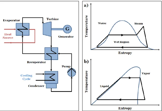
Figure 1: Scheme of an ORC unit Figure 2: TS-diagram for water (a) and an organic fluid (b)
A scheme of the ORC process is depicted in figure 1. The energy transfer from the heat source occurs in a single heat exchanger, the evaporator, where preheating, vaporization and super-heating, provided that superheat is needed, take place. The vapor is then led to the turbine for expansion. Afterwards, it can still be in superheated condition due to the curve characteristics of organic fluids, according to figure 2. The fluids are categorized as wet, dry or isentropic depending on the slope, which can be positive, negative or isentropic of the corresponding saturation curve (Chen n.d.). The recuperator cools the vapor further down close to the condensation condition. In the final step, the vapor condensates in an air-cooled condenser from which the organic fluid is recirculated to the evaporator through the recuperator for preheating purposes (Hattiangadi 2013).
1.1.3 Current Energy Regulation and Legislation in China
The current energy regulation and legislation in China have a long history of development. With the establishment of the People’s Republic of China, the energy sector was subject to the planned economy model meaning that the monthly energy production was controlled and allocated. As of the 1980s, the government has passed many reforms to make a transition from a ‘government controlled’ to a ‘market plus government regulated’ industrial model. Among others, the Renewable Energy Law has been enacted in 2005 and revised in 2009 as a reaction of the increased political attention caused by high pollution, climate change and high energy consumption to promote the utilization of renewable energies (Qiu & Li 2012). These measures led China to become the world largest photovoltaic and solar thermal industries. The latter’s main products are solar thermal collectors for water heaters with an annual growth rate of about 20%, accounting for more than half of the world’s output. By 2008, nearly 60% of the total global installations were made in China meaning that China’s solar thermal industry is mainly driven by its domestic market (UNEP.org 2010; Li 2012).
The solar thermal industry benefited from guidance by the government, which set the direction of development for renewable energies. This measure provided the necessary safety for enterprises to invest in the field. Nevertheless, the renewable energy goals specified in the first Renewable Energy Law in 2005 were low with little support effort and insufficient promotion. The revise of the law in 2009 changed this and the Chinese government released several policies to enhance the use of renewable energy. From 2009 on, companies dealing with solar thermal technologies were accepted to become a member of China’s Consumer Electronics Association. Further, solar water heaters were included for the first time in subsidy policies. Aside from financial policies, China’s government has set out the goals of providing 15% energy from renewable sources as well as reducing carbon dioxide emissions by 40 – 45% by 2020, compared to 2005 (Li 2012).
Despite these efforts, the country’s energy sector is still undergoing many reforms resulting in lack of awareness and enforcement of these laws (Wang 2006; Li 2012). The regulatory authority is still not acting independently and influenced by the political authority. Moreover, about seven departments are in charge of energy related topics leading to uncertainties concerning the areas of responsibility and therefore more complicated licensing procedures (Qiu & Li 2009). Xiaohua Li suggests in his study Development characteristics of the solar
energy industry and related policies in China several adjustments to policies to promote
China’s solar industry. The key recommendations are as follows: Improve goals for solar energy utilization
Speed up the relevant legislation
Strengthen the incentives for solar energy utilization
Provide financial and tax support for solar energy utilization
1.1.4 Project Status and Plant Layout
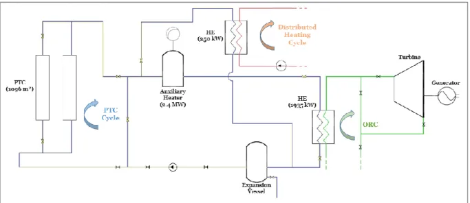
Tianjin University in China is working on a 200 kW solar-driven ORC demonstration plant for the new university research institute in Binhai District. The goal of this project is to establish a distributed energy system (DES) which can be operated for research purposes involving the ORC unit and electricity generation. At this early stage, parts of the power plant, in particular the solar thermal system, which includes a 1096 m² solar field, 2.4 MW auxiliary heater and 250 kW heat exchanger (HE), for the distributed heating cycle, as well as the piping and vessels, have been purchased and installed according to the layout depicted in figure 3. The design conditions for the 250 kW counter flow HE are 45°C inlet and 55°C outlet temperature for the cold fluid and 120°C inlet and 100°C outlet temperature for the hot fluid. The ORC cannot be operated at this current stage due to a missing turbine and generator.
The ORC can either be operated with or without the solar field depending on the availability and amount of solar radiation. If the latter is the case, then the solar field is simply bypassed and the working fluid is pumped directly to the auxiliary heater, where it is heated and subsequently transferred to the ORC HE. At times with sufficient solar radiation, the working fluid is pumped through the solar field to reduce the auxiliary heater’s fossil-fuel consumption. In the current setup, the distributed heating cycle can only be operated in conjunction with the solar field, the auxiliary heater is bypassed.
1.2 Objective and Research Questions
Upon completion of the DES, it will not be connected to the grid due to restrictions by Chinese law and difficulties with the licensing procedure as mentioned in 1.1.3 Current
Energy Regulation and Legislation in China. For that reason, Tianjin University intends to
upgrade the solar-driven ORC unit in order to supply heat to either the local scholar community or nearby industry whenever the plant is not used for power generation. This measure will utilize the harvested solar energy effectively.
Within this framework, the DES is to be upgraded by including a properly sized thermal energy storage system (TESS) to provide heat and cooling to the scholar community during the winter and summer or heat to some industry process throughout the year. In common commercial projects, the solar power plant should be designed to fit the beforehand evaluated and designated utilization purpose in the most cost-effective way before it gets constructed. This study differs from the common procedure in that the plant has been built for other purposes in respect with the ORC unit and should now be upgraded for heating purposes for times without ongoing experiments. Therefore a heating purpose is sought to fit the plant’s specifications most cost-effectively. The considered upgrades were (1) the implementation of a TESS and (2) resizing of HE capacity for the distributed heating cycle. Further, the hot fluid outlet temperature (HFOT) of the HE was reviewed. For this reason, four utilization scenarios have been defined (table 1).
Table 1: Identified and investigated scenarios
S1 S2 S3 S4
TESS size (5 m³ interval) 0 - 35 m³ (10 m³ interval) 0 - 70 m³ (10 m³ interval) 0 - 70 m³ (10 m³ interval) 0 - 70 m³ HE resizing No Yes Yes Yes
HE HFOT 50 - 100°C 50 - 100°C 50 - 100°C 50 - 100°C
Heating purpose Space heating and cooling Space heating and cooling Industrial process heat (24/7) Industrial process heat (16/7)
Scenario 1 (S1) represents the current system setup. None of the purchased components has been upgraded. Solely the HFOT of the HE has been altered with different TESS sizes to study the performance of the system for the current and original design when used for space heating and cooling of the scholar community. Scenario 2 (S2) is similar to S1 with the difference that the heat supply is increased by resizing the HE to utilize more of the harvested solar energy. The heat demand in S1 and S2 still remains very low during spring and autumn season when neither heating nor cooling is required leading to large amounts of not utilized solar energy. For this reason, an industrial process heat demand according to the HE size was applied for scenario 3 (S3) and 4 (S4). Many industries produce in a three working shift system 24 hours, 7 days a week (24/7) and thus a constant heat demand throughout the day and year according to the HE capacity has been applied in S3. A possible candidate in the near vicinity of the plant, which could use the harvested solar energy, works in a two shift system 16 hours, 7 days a week (16/7). To this end, a constant heat demand 16/7 has been used in S4 to investigate the cooperation potential.
The purpose of this thesis, documented in this report, is to conduct a performance analysis of the upgraded system for different utilization possibilities.
Finally, this implies the following concrete subtask:
1) Assessment of the meteorological data for the location Tianjin, China 2) Estimation of space heating and cooling loads
3) Estimation of industrial heating loads 4) Modeling and verification of the system
5) Definition of the performance indicators
1.3 Scope and Limitations
Prior to this thesis work, decisions had been made in terms of component sizing and design parameters such as temperature levels and fluids used in the system. As a matter of fact, most components have been purchased and installed already. Therefore, the investigated options for upgrading the system only involve the TESS and HE. Extending the solar field would require bigger pumps to cycle the heat transfer fluid. This in turn implies higher volume flows and therefore a replacement of all pipes, vessels etc. with larger ones. The latter is seen as not practical and hence neither investigated nor considered in this study. In the current layout of the plant, the auxiliary heater is bypassed when operating the HE for the distributed heating cycle, see figure 3. In the further course of this work, it is assumed that the auxiliary heater can also supply heat to the distributed heating cycle. For that purpose, only minor changes to the piping layout have to be made. The power plant’s site itself has enough space for additional components. However, the space inside the current boiler building is not sufficient. Still, in order to save ground area it is assumed that the TESS tank is standing upright. This study focuses on the preliminary sizing of the TESS, HE and HFOT for the four scenarios. Specific design parameters as well as placement, installation, additional buildings etc. are thus not subject of the report. A fixed exchange rate from July 1st, 2015 of 6.08 for the
Chinese Yuan Renminbi against the US dollar was used throughout this thesis work.
1.4 Thesis Outline
Chapter 2, methodology, describes and justifies the applied methods to accomplish this
thesis. Chapter 3 presents a literature review on the fundamentals of solar radiation, the key components in solar-driven distributed heating units and the theory on heating load estima-tion as well as an overview about different simulaestima-tion software used in connecestima-tion with solar systems. In Chapter 4 the modeling and validation of the model is explained. The structure of the entire model is given first. The chapter proceeds with evaluation of the meteorological data, heating load estimation, the modeling of the solar field, TESS and auxiliary heater be-fore it concludes with the validation of the entire model. The report continues onto Chapter 5 in which the economic, technical and environmental performance indicators are defined. Based on these, the simulation results are presented in Chapter 6 and discussed in Chapter 7.
2
METHODOLOGY
The goal of this thesis has been to identify a heating purpose and corresponding system upgrades leading to the most cost-effective use of the already purchased components. In this context associated literature was studied in order to reflect (1) the state of the art technology regarding the key components of such a system, (2) the methods to estimate heating and cooling loads of office buildings and industrial processes and (3) common used software for modeling and simulation of solar thermal systems. The study for heating and cooling load estimation in office buildings included the Heat Balance and Degree-Day (DD) method. The Heat Balance method requires detailed information about the buildings properties such as insolation type, floor area, occupation etc. This information was not available meaning that the heating and cooling load estimation for office buildings has been determined with the DD method, which requires solely the ambient air temperature and the current Chinese building standard. The obtained heat and cooling profile from this method was simplified to represent the heat that needs to be transferred from the HE. Additionally, the profile was scaled so that the annual maximum heat demand corresponded to the HE capacity. In this way, the solar system could supply as much heat as possible. Finally, the programs TRNSYS, WATSUN and POLYSUN, for simulating solar thermal systems, and MATLAB, for solving general mathematical problems, have been studied in terms of their applicability for the underlying research questions.
Subsequent to the literature review, the system modeling and validation have been carried out. The modeling and simulation of the meteorological data and PTC have been performed with the simulation software TRNSYS due to its ability to process different weather data types and the availability of a detailed component for PTC given through the TESS extension library. The modeling and simulation of the heating load with the DD method, the TESS and auxiliary heater have been realized with MATLAB. It has decisive advantages in respect of flexibility and stability of the calculation compared to TRNSYS.
For the four studied scenarios, the different parameters have been varied for the design evaluation and the results have been subsequently saved into EXCEL for assessment. The results were analyzed in terms of economic, technical and environmental performance. The economic performance is paramount for the utilization of the solar system. Therefore, the setup, leading to the best economic performance, is presented in the results. The associated trends of the technical and environmental performance for the determined setup are also depicted.
3
LITERATURE REVIEW
The utilization of solar radiation provides the foundation for all solar applications. A brief review of the fundamentals is essential for further understanding and therefore subject of the first section. The following section covers the theoretical background of key components in a solar-driven distributed heating unit, in particular solar collectors, TESS, auxiliary heater and heating cycle. For the latter, a reflection on the theory about heating load estimations is of substantial importance. The chapter ends with an overview of programs suitable for modeling and simulating solar thermal systems.
3.1 Fundamentals of Solar Radiation
Simply speaking, solar radiation is a result of a permanently ongoing fusion reaction in the core of the sun. The released energy in the center is transferred by conduction and convection to the outer layer, the so called photosphere, from which it is finally emitted in a continuous spectrum of radiation (Duffie & Beckman 2013).
The extraterrestrial radiation is the part of solar radiation intercepted by the earth’s outer atmosphere and is on average about 1367 W/m². While the radiation passes through the atmosphere, some parts get absorbed by molecules or reflected back to space, others reach the earth’s surface after being scattered by molecules and particles, whereas the remaining part is not scattered at all. The latter two are referred to as diffuse radiation and direct solar radiation or beam radiation, respectively. The amount of radiation reaching the surface depends also on the latitude, longitude and height of the location as well as other weather factors such as season of the year, cloud cover, air pollution etc (Duffie & Beckman 2013; Wald 2009).
For the use of solar collectors the understanding of different sun-earth angles is of importance. These are defined by Tiwari & Dubey (2010) as follows and depicted in figure 4.
The zenith angle 𝜃𝑧 is the angle between the sun’s rays and the zenith direction. The
angle becomes smallest during noon and is 90° at sunrise and sunset.
The solar azimuth angle 𝛾𝑠 describes the location of the sun in respect to south. When it becomes 0° the sun is shining from geographic south in the northern hemisphere. The solar declination 𝛿 (not shown in figure 4) is the angle between the sun and the
equator.
The hour angle 𝜔 describes the rotation of the earth to bring a location directly under the sun. It is maximum negative at sunrise, zero at noon and maximum positive at sunset.
The surface azimuth angle 𝛽 is a measure for the incline of a surface compared to the horizontal. It is of major importance when the solar energy yield by a surface is to be increased throughout the day. The angle can be fixed or variable.
Figure 4: Zenith angle, slope surface azimuth and solar azimuth angle for tilted surface (Yadav & Chandel 2013)
The angle of incidence 𝜃𝑖 is calculated by means of the latitude 𝜙 of the location with
equation 1.
cos 𝜃𝑖 = (cos 𝜙 cos 𝛽 + sin 𝜙 sin 𝛽 cos 𝛾) cos 𝛿 cos 𝜔 + cos 𝛿 sin 𝜔 sin 𝛽 sin 𝛾
+ (sin 𝜙 𝑐𝑜𝑠𝛽 − cos 𝜙 sin 𝛽 cos 𝛾) sin 𝛿 Equation 1 For this thesis work meteorological data was available which provides recorded values for the above mentioned angles. Further explanations of the underlying calculation method are therefore not expedient and reference is made for more information on the topic to Tiwari & Dubey (2010) and Kalogirou (2009).
3.2 Key Components in Solar-driven Distributed Heating Units
The solar collector field is the centerpiece of any solar-driven application. The decision for PTC has already been made prior to this study. As a consequence, only a literature review on these will be presented below. For additional information on other collector types such as flat-plate, compound parabolic, evacuated tube collectors and linear Fresnel or parabolic dish reflectors refer to Duffie & Beckman's comprehensive synopsis Solar Engineering of
Thermal Processes (2013) and Kalogirou's summarized study Solar thermal collectors and applications (2004).
The two-tank thermal and thermocline energy storage systems as well as the auxiliary heater are studied in section 3.2.2 and 3.2.3, respectively.
3.2.1 Parabolic Trough Collectors
Parabolic trough collectors (PTC) belong to the group of concentrating collectors. Unlike stationary collectors, concentrating collectors use an optical device to focus solar radiation on a smaller absorption surface which results in delivering energy at higher temperatures. This implies that processes with concentrating collectors work at higher thermodynamic efficiency than processes with stationary, non-concentrating, collectors, while both have the same solar absorption surface. Further, less material is needed due to large reflecting areas but only small absorption surfaces. At the same time, however, the production of reflecting components requires higher precision to ensure the focus of solar radiation in one line. Moreover, the higher the concentration ratio is the less diffuse radiation can be gathered. Since focusing of solar radiation requires a correct orientation towards the sun the collectors need to be equipped with a sun tracking system which could throw shadows onto the reflecting area. The tracking system raises the investment costs for concentrating collectors compared to stationary collectors. Last but not least, the reflecting area needs to be cleaned regularly from dirt in order to guarantee good reflectance (Duffie & Beckman 2013; Kalogirou 2004).
PTCs usually reach temperatures between 50 and 400°C (Kalogirou 2009). The sun rays are focused by shaping the reflective surface, the so called parabola, parabolic as depicted in figure 5.
Figure 5: Schematic of a parabolic trough collector (Kalogirou 2004)
The receiver is composed of a metal tube in the middle with black coding to increase the ab-sorption. A glass tube surrounds the metal tube to reduce heat loss, however, it also reflects some sun rays coming from the parabola thus adding some transmission losses. The relationship of the aperture’s area 𝐴𝑎 to the receiver’s area 𝐴𝑟 is defined as the concentration
ratio 𝐶 and is one of the essential characteristic of PTCs (equation 2). This value determines, to a great extent, the temperature of the produced heat. The upper theoretical ratio for concentrators, in general, is limited due to the fact that the incident solar beam is not entirely parallel but rather forms a cone with an angle of about 0.5°. Hence, the receiver must be of a certain size, since the reflected beam is also a cone, to gather most of the reflected solar radiation, see Rabl's (1976) Comparison of Solar Concentrators for detailed information about the topic.
𝐶 =𝐴𝑎 𝐴𝑟
In practice, collector arrays are quite long and therefore the usage of a single axis tracking system is sufficient enough, because solely minor concentrating losses occur at the end of the collector array. The orientation of the system highly depends on the application. Table 2 summarizes the advantages and disadvantages of a north-south and east-west oriented tracking system. Furthermore, aside from tracking the sun itself, the system needs to be able to orient the collectors at the end of the day back to its morning position and to continuously track the sun even during periods of cloud cover. A safety mechanism prevents the collector field from operating in dangerous working conditions such as wind gust, overheating etc. by turning the collectors out of focus (Kalogirou 2004).
Table 2: Comparison of north-south and east-west oriented tracking systems
North-South East-West
Advantages
Higher collection during morning and evening hours Little collector adjustment throughout the day Overall energy collection in one year is higher than with an
east-west tracking system Collectors always fully face the sun at midday Collects more energy during winter, this results in less
annual fluctuation Collects more energy during summer
Disadvantages
At midday the collectors performance is the lowest due to
unfavorable orientation towards the sun Large incident angles during morning and evening reduce the collectors yield High fluctuation in energy output
3.2.2 Thermal Energy Storage Systems
Thermal energy storage systems (TESS) have a decisive advantage when it becomes a matter of overcoming fluctuation in energy production due to sunset and clouds. In general, solar energy is stored in and discharged from the tank to ensure an as uniform as possible electricity production or heat availability (SkyFuel 2012). The charging process in detail depends on the TESS technology, but the overall principle is the same. During the day, excessive heat from the collectors which cannot be used for electricity generation or heat applications is used to charge the tank. The stored heat is then discharged during cloudy periods or evening hours for continuously electricity generation and heat supply (Ravaghi-Ardebili et al. 2013).
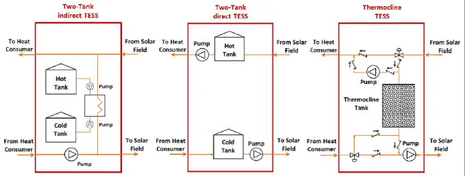
The two-tank indirect system, two-tank direct system and the single-tank thermocline system use sensible heat storage and have emerged as the most significant TESS technologies over the past few decades. The storage medium is circulated actively through all the mentioned systems (Libby 2010; U.S. Department of Energy 2013). The former two-tank indirect system distinguishes itself from two-tank direct system by having a separated, independent heat storage circuit, see figure 6. For this reason, the indirect system is deemed to be the technology with lowest risk. However, this system entails also a non-negligible disadvantage. Two heat transfers, one for charging and one for discharging the storage tank, are necessary. Both require a certain temperature difference in the heat exchanger, meaning that the fluid temperature is 10-20°C lower when the system is operated from the TESS compared to being
operated from the solar collectors. This leads to a storage cycle efficiency of about 93% which, in turn, results in a lower overall system efficiency when operated from the two-tank indirect TESS (Libby 2010).
Figure 6: Simplified schemes of the two-tank in- & direct and thermocline TESS, adapted from Cocco & Serra (2015)
The two-tank direct TESS, depicted in the middle of figure 6, uses the same fluid in the storage tank and collector field and does not require an additional heat exchanger. The storage is charged by pumping fluid from the cold tank through the solar collector field to the hot tank and discharged by circulating the fluid from the hot tank through the heat consumer, namely ORC or distributed heating unit, and finally back to the cold tank. With such a setup it is possible to charge and discharge at the same time when the available solar energy is higher than the required energy of the heat consumer. Two-tank direct TESS stipulate a relatively large amount of working fluid in order to also ensure heat storage. The usage of molten salt as a heat transfer and storage medium is inexpensive compared to synthetic oils hence vital to maintain the financial competitiveness. The disadvantage of molten salt is that it needs to retain a relative high temperature, around 270°C, to avoid solidification of the fluid in any part of the system. Both two-tank TESS are ultimately better suitable for larger applications where solar collectors reach temperatures above the molten salt freezing point (Libby 2010).
The thermocline TESS can either be designed as an indirect or direct single-tank system, see figure 6. The hot and cold fluids are both present in one tank and separated by the thermocline, hot in the top and cold in the bottom part. Further, most of the storage fluid is substituted with less expensive filling material. The charging simply takes place by introducing hot fluid at the top of the tank. It then transfers heat to the filling material by flowing through it to the bottom of the tank where it eventually is returned to the cycle for reheating. Discharging takes place in the opposite way. This method forms a thermal gradient throughout the tank. The temperature of the cold fluid leaving the tank rises with progressive charging which lowers the performance of the solar collector. Likewise, the temperature of the hot fluid, leaving the tank in discharging mode, declines which affects the heat consumer’s performance (Libby 2010).
3.2.3 Auxiliary Heater
Auxiliary heaters operated with biomass, fossil fuels, electricity etc. are usually integrated into solar-driven power plants to guarantee operation at the desired capacity even during periods with low solar radiation and at night as well as when the TESS is discharged. These plants are typically designed to run 100% on solar energy, 100% on the auxiliary heater or any combination of both. However, the achieved efficiency in ORC units with fossil-fuel driven auxiliary heaters is lower than in conventional steam cycles and is therefore only used to cover the demands. The lower heat grade available from, for instance, waste heat recovery is more suitable in combination with ORC units. The type of auxiliary heater in distributed heating applications is from a technical perspective rather insignificant and depends solely on the availability of fossil-fuels and pricing (U.S. Department of Energy 2010).
3.2.4 Solar-Driven Distributed Heating Unit
Solar collectors are used in a variety of applications including heating. A pump circulates the heat transfer fluid through the collectors when there is enough solar energy available. Subsequently, and depending on the unit design, the heated fluid is stored in a tank or supplied to the heat exchanger of the heating cycle. It should be noted that heat can be supplied directly from the collector to the distributed heating unit by using the same heat transfer fluid or indirectly by using a different heat transfer fluid and separated collector cycle. Since the latter is the case for the studied system, direct systems are set aside and are no longer subject of the further review. For more information on that matter, reference is made to Kalogirou's Solar thermal collectors and applications (2004).
The heating load is specified by many factors such as the size of the building and its purpose of the underlying industrial process. Although, the heating load could be satisfied with solar energy only, it would result in an oversized system for most parts of the year, making the system less viable hence the use of auxiliary heating inevitable. The correct sizing of the system is mainly determined by the LCOE described in section 5.1 Economic Indicator. When combining the solar heating system with a TESS and auxiliary equipment equal levels of comfort, temperature stability and reliability can be reached compared to conventional systems (Kalogirou 2004). In such a system, five basic operation modes, depending on the system conditions at a certain time, are considered. Duffie & Beckman (2013) specify them as follows:
1. If solar energy is available and heat is not needed, energy gain from the collector is added to TESS.
2. If solar energy is available and heat is needed, energy gain from the collector is used to cover the heat demand.
3. If solar energy is not available, heat is needed, and the TESS has stored energy in it, the stored energy is used to cover the heat demand.
4. If solar energy is not available, heat is needed, and the TESS has been depleted, auxiliary energy is used to cover the heat demand.
5. If the TESS is fully charged, there are no heat demands to meet, and the collector is absorbing heat.
For the last case, a safety system, such as pressure relief valves or a tracking mechanism that rotates the collectors out of focus, needs to be employed to prevent the system from getting damaged. It is also possible that a combination of two basic modes is applied when, for instance, heat from the collector is available but not sufficient to cover the energy needs of a building or process, meaning that additional auxiliary heating is required. In addition to solar heating, solar cooling for buildings further extends the utilization of the solar-driven heating unit and consequently lowers its LCOE. The utilization is favored even for systems without any storage technology due to the solar cooling loads being in phase with the availability of solar radiation (Kalogirou 2004).
3.3 Heating Load Estimation for Space Heating and Cooling
The load of a distributed heating system is influenced to a great extent by the climate, the building properties such as the heat transfer coefficient from the building to the surrounding but also by the human behavior and temperature comfort levels etc. The lack of this information makes the thermal load calculations complex. Various calculation methods have therefore been developed to estimate heating loads. The following subsections outline the approach.
3.3.1 Heat Balance Method
Results with sufficient precision can be obtained by using heat source, heat gain and heat loss calculation concepts based on transient heat transfer analysis, commonly referred to as ‘The
Heat Balance Method’ (Kalogirou 2009; ASHRAE 2001). The method is based on the
fundamentals of thermodynamics meaning, that all energy flows must be balanced. Heat gains, losses and transfers due lights, computers, humans, solar radiation, outside temperature etc. are therefore considered. However, this method requires a great deal of information about the building’s design and purpose. A detailed explanation of the method is not expedient due to lack of this information and, moreover, would be beyond the scope of this thesis. For further discussion of the heat balance method the reader is referred to Kalogirou's Solar Energy Engineering: Process and Systems (2009), in which equations and correlations are briefly described, and to the ASHRAE Handbook of Fundamentals (2001) which gives a detailed explanation about the method as well as tables and figures with reference data for heat emission of lights, computers, humans and other domestic appliances.
3.3.2 Degree-Day Method
The degree-day method, summarized by Duffie & Beckman in Solar Engineering of Thermal
Processes (2013), can be used if the aforementioned details are not known, as it is the case for
the current project status, in order to estimate the heating and cooling load of a building by taking its ambient temperature, purpose and the building standards into account. The method is based on the principle that energy loss from a building are considered to be proportional to the temperature difference between in- and outdoors, see right hand side of
equation 3. Further, it considers the rate of internal heat generation 𝑔̇ from humans, lights and other appliances leading to the required heating rate 𝐿̇ at which the building needs to be heated to maintain its indoor temperature. The following equations were compiled from Duffie & Beckman (2013) and Dubin & Gamponia (2007), and reference is made to the corresponding literature for a complete derivation.
𝐿̇ + 𝑔̇ = (𝑈𝐴)ℎ∗ (𝑇ℎ− 𝑇𝑎𝑚𝑏) Equation 3
If the building is heated to a desired indoor temperature 𝑇ℎ then there exists an indoor base
temperature 𝑇𝑏 at which the internal heat generation compensates the losses and no heating
is required. Consequently,
𝐿̇ = (𝑈𝐴)ℎ∗ (𝑇𝑏− 𝑇𝑎𝑚𝑏). Equation 4
Finally, the heating load for a desired time span is obtained by integrating all cases where the ambient temperature is lower than the base temperature thus contributing to the heating load. The superscript (+) denotes that only the positive part of the integral is considered.
𝐿 = (𝑈𝐴)ℎ∗ ∫(𝑇𝑏− 𝑇𝑎𝑚𝑏)+𝑑𝑡 Equation 5
Since temperature data is usually given as hourly averages, the load at a specific time step 𝐿𝑖
can be approximated with sufficient precision by using
𝐿𝑖 = (𝑈𝐴)ℎ∗ 𝐷𝐷𝑖 Equation 6 with 𝐷𝐷𝑖 = 1 𝑁∑(𝑇𝑏− 𝑇𝑎𝑚𝑏𝑖) + Equation 7 where 𝐷𝐷𝑖 is the degree-days in °C-day, 𝑇𝑎𝑚𝑏𝑖 is the average ambient temperature of the time
step 𝑖 and 𝑁 the total amount of time steps per day.
The aforementioned equations are also suited to estimate cooling loads if the ambient temperature stays mainly above room temperature. These loads arise as a consequence of energy entering the building through its envelope, as solar gains through windows and ventilation of warmer outside air (Duffie & Beckman 2013).
3.3.3 Chinese Building Standard
The Chinese government has focused more and more on the buildings energy efficiency since the mid-1980s. The Ministry of Housing and Urban-Rural Development (MoHURD) is responsible for developing the Chinese national building energy codes. The MoHURD revised the GB50189 - Design Standard for Energy Efficiency of Public Buildings in 2005 mandating an efficiency improvement by 50% compared to the underlying baseline defined by the 1980s building characteristics (MoHURD 2005). It must be mentioned that the
MoHURD is currently updating the 2005 standard with the ambition of enhancing the energy efficiency by 30% compared to 2005 (Feng et al. 2014). The updated 2014-standard is not active at the current stage of the thesis but it is suspected to become valid without any further changes and will therefore be applied for the further estimation of the heating and cooling load.
An extract of the maximum allowed heat transfer coefficients for the different parts of a building located in China’s cold zone, as it is the case for Tianjin, which will be designed based on GB50180-2014 code, is depicted in table 3.
Table 3: Maximum heat transfer coefficients (U-values), in extracts from MoHURD (2014)
Tianjin, China (Cold Zone)
SC1) ≤ 0.3 0.3 < SC1) ≤ 0.4 Roof ≤ 0.45 ≤ 0.4 Wall ≤ 0.5 ≤ 0.45 WWR WWR ≤ 0.2 ≤ 3.0 ≤ 2.8 0.2 < WWR ≤ 0.3 ≤ 2.7 ≤ 2.5 0.3 < WWR ≤ 0.4 ≤ 2.4 ≤ 2.2 0.4 < WWR ≤ 0.5 ≤ 2.2 ≤ 2.0 0.5 < WWR ≤ 0.6 ≤ 2.0 ≤ 1.8 0.6 < WWR ≤ 0.7 ≤ 2.0 ≤ 1.8 0.7 < WWR ≤ 0.8 ≤ 1.8 ≤ 1.6 0.8 < WWR ≤ 1.0 ≤ 1.5 ≤ 1.4 Floor ≤ 1.5
1) The shading coefficient describes the amount of heat passing through a material compared
to a sheet of clear float glass
The lack of typical parameters such as the building’s shape, number of floors, window-to-wall ratio (WWR) etc. in China had induced Feng et al. (2014) to survey these by examining existing buildings as well as design drawings of new constructions from Chinese design institutes. A reference building based on the Chinese standard is crucial to compare simulation results. The findings and additional information are shown in table 4.
Table 4: Characteristics of the Chinese reference building
Layout 30 m x 50 m1)
Height 85 m2)
WWR 0.41)
Floors 181)
1) Feng et al. (2014) 2) CTBUH (2015)
Further, the GB50180-2014 code advises a set of building operation conditions and schedules such as the heating and cooling set points throughout the day, presented in figure 7.