KTH Engineering Science
Mechanical Properties of Resistance Spot Welds in
Lightweight Applications
Davood Afshari
Division of Lightweight StructuresDepartment of Aeronautical and Vehicle Engineering Royal Institute of Technology
SE-100 44, Stockholm Sweden Licentiate Thesis TRITA- AVE 2013:45 ISSN 1651-7660 ISBN 978-91-7501-838-6
PREFACE
The work in this licentiate thesis has been primarily carried out at the Division of Lightweight Structures Department of Aeronautical and Vehicle Engineering at KTH between December 2010 and September 2013. A number of detours to Iran University of Science and Technology and Linköping University were performed and the Universities together with their Professors are greatly acknowledged.
First and foremost, I would like to express my sincere gratitude to my supervisor, Prof. Zuheir Barsoum (KTH), for being a great supervisor and friend, his continued support and encouragement throughout the process of this work. Prof. Mohammad Sedighi (IUST) and Prof. Ru Lin Peng (Linköping University), with whom I have been working during the research project are also acknowledged.
I would also like to express my gratitude to all of my colleagues and friends that helped me in my research. In particular: Tekn. Lic. Andres Björkblad, Prof. Stefan Halstrom, Dr. Sohrab Kazemahvazi, Dr. Meisam Shahri Mahdavi.
During the years I have had a number of Master thesis students which all helped me in some way. In particular I would like to thank Mr. Mohammad Reza Karimi and Mr. Farshad Nazari for their great efforts and their contribution to this thesis.
I am also grateful to the staff within AB Calibra and Linköping University for their co-operation during the span of this work specially Ms. Annete Billenius.
To Siamak, Babak, Ali, Sherwin and Hamid et al. just to mention a few of you and not being long-winded; thank you for a solid friendship, I know that it will last for a lifetime!
Last but not least, I am forever grateful to my family for their unconditional love and support and my dear wife Parisa for her great patience during these years of hard work.
Stockholm, September 2013 Davood Afshari
i
SAMMANFATTNING
Denna licentiatavhandling behandlar huvudsakligen restspänningar hos punkt svetsar i aluminiumlegering 6061-T6. Även punktsvetsars mekaniska egenskaper behandlas såsom, linsstorlek, mikrohårdhet, mikrostrukturer i svetszon och deras inverkan på hållfastheten hos punktsvetsförband. Andra undersöknnigar som har utförts är; mätning av brottlast med drag-skjuvtest, punktsvetsning simulering och mätning av restspänningar genom röntgendiffraktion metod. Övriga undersökningar som har utförts är effekten av svetsparametrar på de mekaniska egenskaperna. De olika svetsparametrarna som undersökts är; ström, svetstid samt elektordkraft för att producera svetsar med olika kvalité. De olika brottmoderna och brottlasten uppskattades med empirska ekvationer baserat på svetsens linsstorlek samt hårdheten. Mikrostrukur och hårdheten i den samma studerades för att hitta mjuka zoner i svetsgodset.
En elektrisk-termisk-mekanisk kopplad finit element model användes för att prediktera svetsegenpänningarna som i sin tur validerades med röntgen diffraktionsmätningar. Den elektriska-termiska kontakt/konduktansen har använts i kontakten mellan elektrod-aluminium plåt-aluminium plåt. Material egenskaperna som anvnäds i modellen är temperaturberoende. Svetsparametrarnas inverkan på miximala restspänningen i svetsgodset studerades och en regressions model har utvecklats för att prediktera svetsegenspänningarna som funktion av svetsparametrar.
Den validerade finit element modellen har även använts för att utveckla två artificiella neurala nätverk modeller för att prediktera svetsegenspänningarna och linsstorleken, vilka visar på noggrannhet och god överensstämmelse med mätningar. Genom att kombinera dessa två modeller så kan linsstorleken samt svetsegenspänningarna predikteras som funktion av svetsparametrarna kostnadseffektivt och med god noggrannhet.
ii
ABSTRACT
This licentiate thesis is concerned with residual stresses in aluminum alloy 6061-T6 resistance spot welded joint. Several topics related to mechanical strength of welded structures are treated such as; nugget size and microhardness and microstructures of weld zone and their influence on mechanical strength of welded structure, failure load measurement using tensile-shear test, resistance spot welding simulation, residual stress measurement by X-ray diffraction method and analysis effect of welding parameters on the mechanical strength and the residual stresses.
To investigate the effect of resistance spot weld parameters on mechanical strength of welded structures, various welding parameters e.g. welding current, welding time and electrode force are selected to produce welded joints with different quality. According to the failure mode, the empirical equation was used to prediction of failure load base on nugget size and hardness of failure line. Microstructure study has been carried out to investigate microstructural changes in the welded joints. Microhardness tests are done to find hardness profiles due to microstructural changes and determine the minimum hardness.
In addition, an electro-thermal-structural coupled finite element model and X-ray diffraction residual stress measurement have been utilized to analyze residual stresses distribution in weld zone. The electrical and thermal contact conductance, as mandatory factors are applied in contact area between electrode-workpiece and workpiece-workpiece to resolve the complexity of the finite element model. The physical and mechanical properties of the material are defined as thermal-dependent in order to improve the accuracy of the model. Furthermore, the electrodes are removed after holding cycle using the birth and death elements method. Moreover, the effect of welding parameters on maximum residual stress is investigated and a regression model is proposed to predict maximum tensile residual stresses in terms of welding parameters.
The results obtained from the finite element analysis have been used to build up two back-propagation artificial neural network models for the residual stresses and the nugget size prediction. The results revealed that the neural network models created in this study can accurately predict the nugget size and the residual stresses produced in resistance spot weld. Using a combination of these two developed models, the nugget size and the residual stresses can be predicted in terms of spot weld parameters with high speed and accuracy.
iii
APPENDED PAPERS
Paper A
Afshari D., Sedighi M., Barsoum Z. and and Peng R. L., An approach in prediction of failure in resistance spot welded aluminum 6061-T6 under quasi-static tensile test, published in
Proceedings of the Institution of Mechanical Engineers, Part B: Journal of Engineering Manufacture, Vol. 226, No. 6, 2012.
Paper B
Afshari D., Sedighi M., Karimi M. R. and Barsoum Z., On Residual Stresses in Resistance Spot Welded Aluminum Alloy 6061-T6: Experimental and Numerical Analysis, accepted for
publication in Journal of Materials Engineering and Performance.
Paper C
Afshari D., Sedighi M., Karimi M. R. and Barsoum Z., Prediction of nugget size in resistance spot welding by combination of finite element analysis and artificial neural networks, accepted
iv
DIVISION OF WORK BETWEEN AUTHORS
Paper A
D. Afshari carried out tensile-shear test, microstructure analyzing, nugget size and microhardness measurements, developed empirical relation, evaluated results and wrote the papers. M. Sedighi contributed to the paper with valuable comments and discussion. Z. Barsoum planned the work and helped to write the paper. R. L. Peng contributed to microstructure study and nugget size measurement.
Paper B
D. Afshari carried out residual stress measurement, developed finite element model, evaluated results and wrote the papers. M. Sedighi contributed to the paper with valuable comments and discussion. M. R. Karimi helped to develop the finite element model. Z. Barsoum planned the work and helped to write the paper.
Paper C
D. Afshari carried out residual stress measurement, developed finite element model, measured nugget size, developed artificial neural network, evaluated results and wrote the papers. M. Sedighi contributed to the paper with valuable comments and discussion. M. R. Karimi helped to develop the finite element model. Z. Barsoum planned the work and helped to write the paper.
v
TABLE OF CONTENTS
SAMMANFATTNING………i
ABSTRACT………...………..ii
APPENDED PAPERS………...……...iii
DIVISION OF WORK BETWEEN AUTHORS………...iv
TABLE OF CONTENTS……….………....v
INTRODUCTION………...1
Background………..………..1
Research aim………..………2
Research approach……….3
MECHANICAL STRENGTH OF WELDED JOINTS………..….3
FINITE ELEMNT MODEL………...4
RESIDUAL STRESS MEASURMENT………...6
EFFECT OF WELDING PARAMETERS ON RESIDUAL STRESS………...7
ARTIFICIAL NEURAL NETWORK MODEL………12
DISCUSSION………15
CONCLUSIONS………16
SUGGESTION FOR FUTURE WORK………17
SUMMARY OF APPENDED PAPERS………...17
1
INTRODUCTION
Background
Increasing limitations in terms of performance, pollution, safety and reducing of energy resources have resulted in research into the reducing of weight in industrial components and equipment such as cars, trucks, airplanes, trains and etc. Weight reduction can obtained through use of light structure like aluminum and better joining process such as resistance spot welding (RSW). Nowadays, aluminum alloys are used widely in automobile industries. In addition, developing in metallurgy science led to producing new aluminum alloy with higher strength-to -weight ratio, better weldability, enhanced formability and improves corrosion resistance relative to conventional aluminum alloys. [1]
Figure 1. Material distribution in a lightweight car [2]
Although some new joining process have been used to manufacture of structures, such as laser beam welding and friction stir welding, resistance spot welding is still major process to joining sheet metal in automotive industries. This welding method can be used easily for bodies and chassis of automobiles, trucks, buses, trains and even airplane and many other products. For example there are 3000-6000 spot welds in a car [3]. Compared with other welding process RSW has several advantages; RSW is fast, simple, and easy automated and easy maintained. The schematic of RSW is shown in figure 1. In resistance spot welding process, a high electric current is passed through two sheets via electrodes in a short time that results in the generation of a melting zone between the sheets. When the electric current is turned off, molten metal starts to cool down to room temperature non-uniformly. This large temperature gradient from the melting point to room temperature, as well as phase changes occurring in solidifying metal leads to residual stresses retained in spot welded joint. [4].
2
Figure 2. The schematic of RSW [5]
Residual stresses significantly affect stress corrosion cracking, hydrogen-induced cracking and fatigue strength. Regardless of the loading conditions on spot welded joints, tensile residual stress deteriorates the fatigue strength and the quality of the joint [6]. Therefore, it is necessary to control the residual stresses in spot welds and identify spot weld parameters affecting them. There are three major types of residual stress measurement; destructive, semi-destructive methods and non-destructive methods and all of them are costly and time consuming. Furthermore, residual stress measurement in complex welded structure is usually difficult. As a result of the complexity involved in the measurement of residual stresses, there has been an increasing use of numerical simulation procedures for estimating or predicting residual stress in weldments. The most widely used and straightforward tool for stress analysis is the finite element method (FEM) [4]. However, previous numerical simulations on RSW have been mainly based on temperature distribution, nugget growth and electrode design, but the residual stresses have been rarely considered in RSW simulations especially for aluminum alloys.
Research aim
This research aims to study mechanical strength and residual stresses in resistance spot welding of aluminum alloy 6061-T6 with 2 mm thickness and analyze effect of RSW parameters. More specially, the research questions and issue addressed are:
Developing FEM models for simulation of RSW.
Study the formation of residual stresses due to the RSW process. Analysis effect of RSW parameters on formation of residual stresses. Predict the maximum tensile residual stress in terms of RSW parameters.
3
Research approach
The research can be divided in four different items: 1. Studying mechanical strength of welded
Manufacture of lap-shear joint test for tensile-shear testing, microstructure analyzing, microhardness and nugget size measurement, in order to compare the performance of different welding parameters with respect to weld mechanical strength.
2. Welding Simulation
Finite element modeling and simulation of the RSW process, 2D asymmetric model, was carried out using electro-thermal-mechanical coupled with temperature-dependent material properties. Also residual stresses formation in RSW process was studied.
3. Residual stress measurements
Residual stress measurements were carried out using the X-Ray diffraction method in order to study the actual residual stress in the weld joint and validate the finite element model.
4. Parametric study
Analysis effect of the RSW parameters such as welding current, welding time and electrode force, on weld quality and residual stresses and develop an empirical relation, regression model and artificial neural network (ANN) model to predict tensile-shear load, nugget size and residual stresses in RSW process.
MECHANICAL STRENGTH OF WELDED JOINTS
Although spot welding of aluminum alloys is more difficult than steels because of their narrow plastic rang, low bulk resistance and greater thermal conductivity aluminum alloys are used for the bodies and chassis of many components due to their lightweight and relatively high strength which result in reduction of the vehicles structural weight, the fuel consumption and the exhaust emissions [1, 7 and 8]. Typically, joints quality and performance can dramatically alter the structural performance of vehicles and has a critical role in durability and safety design of vehicles [3], so control of welding parameters is necessary to obtain high weld quality and increase vehicles life.
To study mechanical strength of welded joints, in this study several experiments had been done including: tensile-shear test, microhardness measurement, microstructure study and nugget size
4
measurement. In Paper A the experimental procedures of these tests are presented. Also the effect of welding parameters on hardness of welding zone and failure load is investigated and an empirical relation is developed to predict failure load in tensile-shear test in terms of nugget size.
FINITE ELEMNT MODEL
Aluminum alloys normally have high thermal conductivity, low melting temperature, and low yield strength. So, simulation of their spot weld process is more difficult than steels and needs some considerations. As mention before, in this work a fully coupled structural-thermal-electrical axi-symmetric model was utilized for the finite element analysis. The equations in this work are based upon a two-dimensional cylindrical coordinate system. The governing equation for calculation of the electrical potential φ in the entire model is:
0 ) ( z C z t r C r C r e e e (1)
Where r is the radial distance, z is the distance in the axis direction and C is the electrical e conductivity. Based on Joule heat equation, the heat generation per unit volume, q, can be shown as:
⁄ (2)
Where t is the time and R is the material electrical resistance. The governing equation for transient temperature field distribution by considering electrical resistance heat can be presented as: q z T k z r T r k r T k r t T C (3)
Where ρ is the material's density, C is the heat capacity, T is the temperature and k is the thermal conductivity. For stress and strain analysis, the governing equation is described in incremental form for finite element model:
D
C T (4)Where vectors * + and * + are stress and strain increment respectively, matrix , - is the elastic-plastic matrix and vector {C} can be defined by:
5
T D D C e e 1 (5)Where matrix , - is the elastic matrix and vector * + contains the coefficient of thermal expansion.
The contact resistance is a major factor that influences the analysis of Joule heating [6]. In addition, the temperature has a significant impact on value of the contact resistance. In this study, a practical representation of contact resistance is utilized [9]:
( ) ( ) ( )√ ( )
( ) (6)
Where ( ), ( ), ( ) and ( ) are contact resistance and average yield
stress at and respectively, ( ) is contact resistivity, l is the element length and is the contact area. The values of ( ) for electrode-workpiece and workpiece- workpiece are considered 30 μΩ and 65 μΩ respectively [10].
Since the thermal conductivity of aluminum alloys is normally three times higher than that of steels, the spot welding simulation process becomes more difficult and sensitive in aluminum alloys as compared to steels. To achieve higher accuracy in the finite element model, the thermal contact conductance of aluminum sheets is calculated by taking the impact of temperature, pressure and surface roughness into account. The simplest and the most applicable equation to calculate this factor is [11]:
( √
́) (7)
Where hc is the thermal contact resistance, σ is surface roughness, m is the roughness slope and P
is the pressure in contact area. Furthermore, and ́ are equivalent thermal conductivity and elastic modulus of the two materials in contact area which are described by:
( ) (8)
́ , - (9)
Where k1, k2, υ1, υ2, E1 and E2 are thermal conductivity, Poisson ratio and Young modulus for
materials 1 and 2 respectively.
The aluminum sheets used in our experiments are aluminum alloy 6061-T6 with 2 mm thickness with this chemical composition: Al 97.0 %Wt, Si 0.6 %Wt, Mn 0.1 %Wt, Mg 1.0 %Wt, Fe 0.5 %Wt, Cu 0.2 %Wt, Cr 0.1 %Wt, Ti 0.15 %Wt and Zn 0.2 %Wt. In this work, temperature-dependent physical (table 1) and mechanical properties (table 2) of the material are used for both
6
electro-thermal and thermal-mechanical analysis in FE model to improve accuracy of the FE model. The approach of the FE model is presented in Paper B.
Table 1. Physical properties of the aluminum alloy 6061-T6 [12]
Coefficient of thermal expansion ( C−1×10⁻⁶) Thermal conductivity (W/m K) Specific heat (J/kg K) Density (kg/m3) Temperature ( C) 22.4 162 917 2700 0 24.61 177 978 93 26.6 192 1028 201 27.6 207 1078 316 29.6 223 1133 428 34.2 253 1230 571
Table 2. Mechanical properties of the aluminum alloy 6061-T6 [13]
Poisson's ratio Yield stress (MPa)
Elastic modulus(GPa) Temperature ( C) 0.33 275 69.7 25 240 61 177 165 54 260 90 47 315 55 38 370 32 16.7 400
RESIDUAL STRESS MEASURMENT
There are many procedures and methods to measure residual stresses in metallic component. Typically, residual stress measurement methods are divided in three categories in terms of the degree of damage to the metal they introduce: destructive, semi-destructive and non-destructive methods. Destructive methods of residual stress measurement are fundamentally stress relaxation procedure; that is, the information is obtained by relaxing the residual stress in some finite volume of the component by sectioning, drilling or milling (electrical or mechanical) and measuring the resulting strain change. The strain change is then used, along with applicable assumption about the nature of the stress field, to reconstruct the original stress field. Electrical resistance strain gage technologies are emphasized as the dominant method of strain measurement due to their economic, procedural and precision advantages over the other methods. Between destructive and non-destructive methods, which have a severe effect on the service ability, strength and properties, are the semi-destructive methods. These are methods that have a
7
small or negligible effect on the component in which stresses are measured, or methods in which the component may be repaired after the measurement. Hole-drilling is the most commonly used method in this manner [14].
Non-destructive procedures measure a dimension in the crystal lattice of the metal or some physical parameter affected by the crystal lattice dimension. Whenever a mechanical force, resulting in stress that is less than the yield strength, is placed on a solid metal component, that component distorts and strains elastically. The elastic strain results in a change in the atomic lattice dimension, and this dimension, or change, is measured by the non-destructive stress-measurement procedure. Briefly, in this category the following methods of stress stress-measurement are existed:
X-Ray diffraction Neutron diffraction Ultrasonic velocity
Magnetic Barkhausen noise
Due to the size of nugget in RSW process, in this study X-Ray diffraction method was utilized to measure the residual stresses in welded joints. The details of this process is presented in Paper B. Furthermore, the data were compared with the results obtained from FE model to validate the model.
EFFECT OF WELDING PARAMETERS ON RESIDUAL STRESS
The results obtained from the finite element model indicate that for different values of resistance spot welding parameters, the location of the maximum tensile residual stress is fixed and it occurs at the center of the nugget and on the line of contact of two sheets with each other and by moving towards the sheet edges, these stresses diminish (figure 3). Since the increase of tensile residual stresses can lower the fatigue life and strength of a joint, therefore the amounts of theses stresses left in the joint are of high concern. Considering this issue, the present study has investigated the impact of spot welding parameters on the maximum value of tensile residual stress.
8
Figure 3. Stress distribution at the end of the cooling cycle
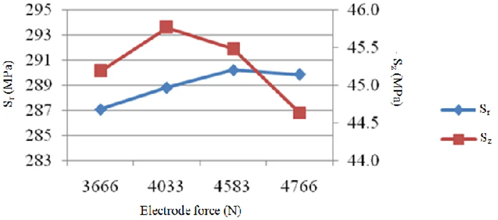
Figure 4 shows the effect of increasing the electrical current on the maximum value of tensile residual stress in two directions of r and z. The results presented in this figure correspond to the simulation of spot welding with a content welding time of 4 cycles and constant electrode force of 4033 N. As figure 4 illustrates, by increasing the welding current from 36 to 37 kA, both stress values along the r and z axes decrease. Stresses in the z and r directions diminish by 20 MPa and 40 MPa, respectively. With the further increase of the welding current, the obtained residual stress does not change significantly compared to the initial state. The reduction of residual stress in the center of the spot weld depends on the weld nugget dimensions. With the increase of the welding current, the maximum temperature does not change by much, while the size of the weld nugget increases; and thus, the rate of temperature reduction (despite a fixed amount of holding time) decreases in the model and as a result, the maximum residual stress diminishes.
9
Figure 5 shows the impact of welding time on the maximum value of tensile residual stress. For the results presented in this figure, the electrical current and electrode force have constant values equal to 36 kA and 4033 N, respectively. As is shown in this figure, the effect of welding time on the maximum tensile residual stress is similar to the effect of electrical current. With the increase of the welding time, the maximum tensile residual stress diminishes in both the r and z directions. This fact demonstrates that the increase of the electrical current and welding time, which causes an increase in the weld nugget diameter; leads to the reduction of the cooling rate and thus, to the reduction of residual stresses.
Figure 5. Effect of welding time on maximum internal residual stress (interface of two sheets)
Figure 6 shows the impact of the electrode force on the maximum value of tensile residual stress at the electrical current of 36 kA and welding time of 4 cycles. According to figure 6, electrode force has a negligible impact on the maximum tensile residual stress. With the increase of the electrode force along the sheet length, contrary to the results obtained on the effect of electrical current and welding time, the amount of maximum residual stress increases. However, along the thickness of the sheet, the increase of electrode force (as compression) has led to the reduction of maximum tensile residual stress.
10
To evaluate the effect of spot welding parameters on the maximum tensile residual stress, the “Full Factorial” method has been used. This approach requires the use of minimum and maximum values of each parameter considered in the study. With respect to the three investigated parameters of electrical current, welding time and electrode force, the minimum and maximum values of each parameter should be considered, and 8 tests, in total, should be ultimately selected for evaluation. In performing the tests, the selection of minimum and maximum values of welding current and welding time are based on achieving the recommended weld nugget size [15] and the prevention of melt explosion from the weld zone. As a result, the values of 36 and 40 kA were selected for the welding current, 4 and 8 cycles were chosen for the welding time, and 4033 and 4766 N were selected for the electrode force.
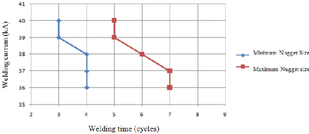
Unfortunately, the above mentioned values cannot be used for the analysis; because experimental tests have demonstrated that with an electrical current of 40 kA at welding times longer than 5 cycles, explosion occurs in the welding zone, which reduces the weld nugget size and lowers the strength of the joint. Therefore, with regards to experimental trials, a minimum and maximum range has been designated for the weld nugget size. Based on the recommendations of AWS [16], the minimum value of weld nugget diameter has been considered as 5.6 mm; and with regards to the prevention of melt spattering, its maximum value has been regarded as 8.5 mm. Considering these explanations and using the simulation based on the finite element model, the acceptable size of the weld nugget has been obtained with respect to the values of electrical current and welding time (Figure 7).
Figure 7. The acceptable size of the weld nugget
In view of Figure 7, the newly selected spot welding parameter values are listed in table 3. Based on the parameters presented in table 3, the simulation of residual stress in the spot weld was performed by the finite element model and the maximum value of tensile residual stress in each test was determined. Figure 8 shows the results obtained from the full factorial analysis of the selected values. It should be mentioned that in this analysis, the influence coefficient of
11
has been used to evaluate the influence of each spot welding parameter on the maximum residual stress obtained from the spot welding process.
Table 3. The selected spot weld parameters for full factorial analysis
Force (N) Time (cycle) Current (kA) Sample Force (N) Time (cycle) Current (kA) Sample 4033 4 38 5 4033 4 36 1 4766 4 38 6 4766 4 36 2 4033 6 38 7 4033 6 36 3 4766 6 38 8 4766 6 36 4
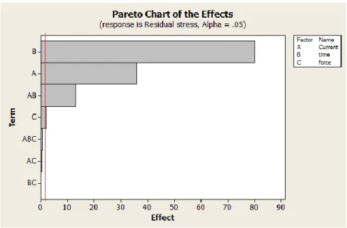
Figure 8. The effects of spot weld parameters on maximum residual stress
As is observed in figure 8, the electrical current, welding time, and the interaction between these two parameters have the highest influence on the maximum value of tensile residual stress in the spot weld. The results of this analysis indicate that the force of electrodes has a negligible impact on the maximum residual stress.
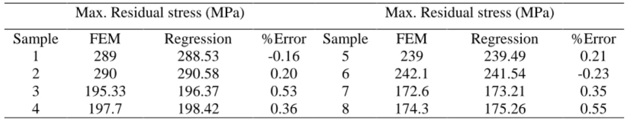
In view of the results obtained from the analysis, a linear regression model has been presented for the prediction of maximum tensile residual stress by using the three parameters of electrical current, welding time and electrode force and the interaction between the welding current and welding time. Equation 10 expresses the obtained linear regression model for the prediction of maximum tensile residual stress. In this relation, σ is the maximum tensile residual stress, C is the welding current, t is the welding time and F is the electrode force. Table 4 outlines the comparison between the results obtained from the FEM simulation and the regression model for
12
the samples presented in Table 3. This comparison indicates very good correlation between the obtained results.
σ (10)
Table 4. The comparison between the results obtained from the FEM simulation and the regression model
Max. Residual stress (MPa) Max. Residual stress (MPa)
%Error Regression FEM Sample %Error Regression FEM Sample 0.21 239.49 239 5 -0.16 288.53 289 1 -0.23 241.54 242.1 6 0.20 290.58 290 2 0.35 173.21 172.6 7 0.53 196.37 195.33 3 0.55 175.26 174.3 8 0.36 198.42 197.7 4
ARTIFICIAL NEURAL NETWORK MODEL
Although the use of FE model eliminates the costs associated with residual stress measurement tests, however due to the complexity of spot welding, the FE models developed for the simulation of these stresses usually require long computation times. The method of artificial neural networks (ANN) is considered as an effective approach for the solving of non-linear problems. The quick learning ability and high speed of solution finding in the ANN has led to a more extensive use of this method in recent years for the modeling of residual stresses in many fabrication processes [17]. The joint use of FE analysis and ANN can eliminate the high costs of laboratory tests and significantly shorten the time it takes to arrive at a solution. In this thesis, a FE model along with an ANN has been adopted for the prediction of residual stresses in the spot welds of a 2 mm thick aluminum 6061-T6.
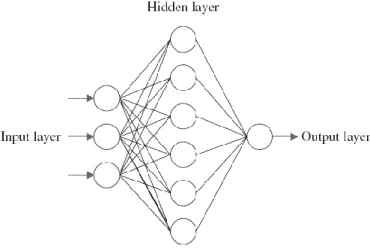
In this investigation, a back-propagation ANN has been employed to predict the residual stresses in spot weld. Structurally, every ANN is made up of three sections (figure 9). The initial section corresponds to the input layer of the ANN. In the present work, the three parameters of welding current, welding time and the electrode force have been used as network inputs. The number of layers and neurons of the middle section, or hidden layer, are determined by trial and error method. The end section of the network is the output layer. Since the residual tensile stresses of the weld zone play a significant role in the quality of the welded joint, the maximum value of tensile residual stress in the weld area has been used as the ANN output. The training algorithm of Levenberg-Marquad has been employed to train the ANN. This training algorithm characterizes a very quick learning speed.
13
Figure 9. A typical artificial neural network
As was previously mentioned, the input parameters considered for the ANN are: welding current, welding time and electrode force. The selection of parameter values is based on achieving a weld nugget diameter of at least 5.6 mm for 2 mm thick sheets (recommended by [15]) and a lack of melt explosion in the weld zone. Considering the results obtained from a nugget measurement, for 2 mm thick aluminum 6061-T6 sheets, at a weld nugget diameter above 8.5 mm, spattering of melt during the spot-welding operation is predictable. Therefore, the selection of spot welding parameters are based on the simulation results of the FEA for achieving a weld nugget diameter between 5.6 and 8.5 mm. Table 5 shows the considered spot welding parameters along with the maximum values of tensile residual stress obtained from the FE model. Of the 51 sets of parameters presented in table 5, 5 samples (sample numbers 4, 16, 23, 33 and 38) were randomly selected and used for the testing of the ANN. The remaining samples (46 samples) were used for the training of the ANN.
By testing different structures of the ANN, it was determined that an ANN with one hidden layer and 12 neurons in this layer has the lowest error in the prediction of the maximum tensile residual stress. Figure 10 shows the result of training the ANN developed by using the data obtained from the FE model. As this figure indicates, the presented ANN has been well trained.
After training the created ANN, the network was tested by employing the 5 samples that had not been used in the training of the ANN. The result of testing the ANN has been shown in figure 11. Table 6 compares the results obtained from the testing of the ANN with those obtained from the FE model. The obtained results demonstrate that the created ANN enjoys a good accuracy (less than 3% in absolute average of errors) in the prediction of maximum tensile residual stress based on the cited spot welding parameters and that this network can be used reliably for the prediction of residual stress in the spot weld of 2 mm thick aluminum 6061-T6 sheets. In addition, another ANN model was developed to predict nugget size presented in Paper C.
14
Table 5. Spot weld parameters and the maximum tensile residual stress obtained from the finite element model
15
Figure 11. The results of neural network test
Table 6. Comparison between finite element results and the test of the neural network
%Error r (ANN) MPa σ r (FEM) MPa σ Sample No. -4.9 159.7 167.9 4 2.1 225.7 221 16 3.2 223.4 216.5 23 2.1 227.7 223 33 -1.3 167.7 169.9 38 2.7 Absolute Average DISCUSSION
Due to their high strength-to-weight ratio, excellent corrosion resistance, low recycling cost, etc., aluminum alloys have been considered as substitute materials for steel alloys in cars, trucks, railroad cars, buses and similar products in order to reduce vehicle weight, improve fuel economy and reduce exhaust emissions. Traditionally, resistance spot welding has been used widely for welding purposes in steel sheets and even aluminum alloy sheets, which are more difficult to weld than steel. In thermal properties of aluminum alloys, the oxide film that covers the surface and high rate of electrode wear make the spot welding of aluminum alloys more sensitive.
16
Nowadays, many industries use aluminum alloys sheets in their product to reduce weight of component and absolutely fuel consumption which is really critical in new millennium. The global demand for saving resources will promote the development of more light-weight structure such as aluminum alloys for many types of machines.
Generally, the quality of welded joints in a structure determines the performance and durability of that structure. So, control the welding process and the quality of the welded joints is really essential and critical in each manufacturing process. In this term, residual stress plays active role. They can significantly affect stress corrosion cracking, hydrogen-induced cracking and importantly fatigue strength and life. The complexity of the residual stress analysis on welded structure is probably the main reason for the limited number of studies on this field. Although several studies have been conducted on the simulation of the residual stress in resistance spot welded steel, the subject of the residual stress in resistance spot welded aluminum alloys has seldom been researched. Since aluminum alloys have high thermal conductivity, low melting temperature and low yield strength, deformation resulting from resistance spot welding is expected to be more severe in aluminum than in steel.
It is clearly obvious that the residual stress analysis and investigation the effect of resistance spot weld’s parameters on that is really important to produce light-weight and effective welded structures. The previous studies indicated that in welded joints, if the residual stress level is in tension, then the fatigue life will be shorter than if the residual stress is in compression [14]. As the residual stress measurement is expensive and time consuming, the computational effort needed to predict the distribution, level and amount of the residual stress in welded joints. By using a reliable model, the effects of welded parameters on the residual stress are attainable and also the optimum welding parameters of welding process and welded structure are predictable. Finally, the challenge for the international researchers and industries, in order to select the suitable welding parameters to be able to manufacture light-weight structures may be listed as:
- Increasing the mechanical strength of welded joints, - Reducing the tensile residual stress in weld zone,
- Predicting the failure load of welded joints in different loading conditions
CONCLUSIONS
With increasing welding current and welding time, nugget size and mechanical strength
are improved. However, increasing the welding time and the welding current should be controlled to avoid expulsion in the welding zone.
Between nugget and heat affected zone, there is a thin layer with large and coarse grains.
17
critical one in failure conditions and failure line creates in this area. The results of this study show that with good agreement, failure load in quasi-static tensile test can be calculated based on nugget size measuring and evaluation microhardness of the area around the nugget.
The highest internal tensile residual stress occurs in the center of the nugget zone and
decreases slightly towards the nugget edge. The behavior of the surface residual stress is different, and decreases from center of the weld zone towards the edge of the nugget. However, after this area, the value of the residual stress falls down.
With increasing the welding current and the welding time, the residual stress is decreased
in the weld zone. However increasing the welding time and the welding current boil down to increase input heat to the weld zone, the maximum temperature doesn’t change by much, while the size of the weld nugget increases; and thus, the rate of temperature reduction (despite a fixed amount of holding time) decreases and as a result, the maximum residual stress diminishes.
SUGGESTION FOR FUTURE WORK
Study the fatigue behavior of RSW joint and analysis the effect of residual stress on
fatigue strength.
Develop a fatigue design recommendation for RSW welded thin Aluminum structures
based on local stress methods and fracture mechanics.
Investigate the electrode wear in RSW of aluminum alloys and find the optimum welding
parameters to increase the mechanical strength and reduce the residual stress and electrode wear.
SUMMARY OF APPENDE PAPERS
In Paper A mechanical strength of resistance spot welded joints is examined. 12 sets of welding parameters were considered to investigate effect of welding parameters on the nugget size and failure load of the welded joints under quasi static tensile-shear test. Microhardness was measured and microstructures in weld zone were studied to find relation between failure load and nugget size. The results showed that increasing the welding current and the welding time result in the mechanical strength and nugget size improvement. In addition, in this paper, an empirical relation was developed to predict failure load of welded joint in tensile-shear test.
18
In Paper B an incremental fully coupled structural-electrical-thermal finite element model was developed to study the residual stress distribution in weld zone. The residual stresses were measured by the X-Ray diffraction method to validate the results obtained from the finite element model. In this model, physical and mechanical properties of material were defined as temperature – dependent to improve accuracy. The results showed that, however, the highest internal tensile residual stress occurs in the center of the nugget zone and decreases towards nugget edge; surface residual stress increases towards the edge of the welding zone and after that area decreases slightly.
In Paper C a backpropagation neural network was joined with the finite element model to predict the nugget size. Actually, the results obtained from the finite element model were used to build up the artificial neural network model. The finite element analysis was carried out to design welding parameters schedule which are acceptable to produce welded joints with recommended nugget size and avoid explosion in weld zone. The results revealed that the combination of these two developed models can accurately and rapidly predict nugget size in resistance spot weld.
REFERENCES
[1] Pereira A. M., Ferreira J. M., Loureiro A. J., Costa D. M and Bartolo P. J., Effect of process parameters on the strength of resistance spot welds in 6082-T6 aluminum alloy, Materials & Design, Vol. 31, No. 5, pp. 2454-2463, 2010.
[2] http://www.worldautosteel.org
[3] Sun X., Stephens E. V. and Khaleel M. A., Effect of fusion zone size and failure mode on peak load and energy absorption of advanced high strength steel spot welds under lap shear loading conditions, Engineering Failure Analysis, Vol. 15, No. 4, pp. 356-367, 2008.
[4] Long X. and Khanna S. K., Residual Stresses in Spot Welded New Generation Aluminium Alloys Part B – Finite Element Simulation of Residual Stresses in Spot Weld in 5754 Aluminium Alloy, Science and Technology of Welding and Joining, Vol. 10, pp. 88-94, 2005.
[5] Mthers G., Welding of Aluminum and its alloys, Woodhead publishing, 2002.
[6] Cha B. W. and Na S. J., A Study on The Relationship Between Welding Conditions and Residual Stress of Resistance Spot Welded 304-Type Stainless Steels, Journal of Manufacturing System, Vol. 22, No. 3, pp. 181-189, 2003.
19
[7] Chao Y. J., Ultimate strength and failure mechanism of resistance spot weld subjected to tensile, shear, or combined tensile/shear loads, Journal of Engineering Materials and Technology, Vol. 125, pp. 125-132, 2003.
[8] Hassanifard S. and Zehsaz M., The effect of residual stresses on the fatigue life of 5083-O aluminum alloy spot welded joints, Fatigue, Vol. 2, No. 1, pp. 1077-1085, 2010.
[9] Tsai C. L., Dia W. L., Dickinson D. W. and Papritan J. C., Analysis and Development of Real-Time Control Methodology in Resistance Spot Welding, Weld. J., Vol. 69, pp. 339-351, 1991. [10] Babu S. S., Santella M. L., Feng Z., Riemerand B. W. and Cohron J. W., Empirical Model of Effects of Pressure and Temperature on Electrical Contact Resistance of Metals, Science and Technology of Welding and Joining, Vol. 6, No. 3, pp. 126-132, 2005.
[11] Rohsenow W. M., Hartnett J. R. and Cho Y. I., Handbook of Heat Transfer, 3rd ed., McGraw-hill; New York, 1998.
[12] Chao Y. and Qi X., Thermal and Thermo-Mechanical Modeling of Friction Stir Welding of Aluminium Alloy 6061-T6, Journal of Material Processing Technology, Vol. 7, pp. 215–233, 1998.
[13] Hirsch J., Skrotzki B. and Gottstein G., Aluminum Alloys: Their Physical and Mechanical Properties, Weinheim Wiley-veh, 2008.
[14] Barsoum Z., Residual stress analysis and fatigue assessment of welded steel structures, Doctoral Thesis, Dept. of Aeronautical Structres and Vehicle Engineering, KTH, Sweden 2008, ISSN 1651-7660.
[15] American Society of Mechanical Engineers, Qualification Standard for Welding and Brazing Procedures, Welders, Brazers and Welding and Brazing Operators (ASME IX), New York, AWS, 2006.
[16] - American National Standard, Weld button criteria, recommended practice for test methods for evaluating the resistance spot welding behavior of automotive sheet steel metal, ANSI/AWS/SAE/, 1997.
[17] Raja Dhas, J. E. and Kumanan, S., Modeling of residual stress in butt welding, Material and Manufacturing Processes, Vol. 26, pp. 942-947, 2011.
![Figure 1. Material distribution in a lightweight car [2]](https://thumb-eu.123doks.com/thumbv2/5dokorg/4630609.119723/8.918.234.690.412.690/figure-material-distribution-lightweight-car.webp)
![Figure 2. The schematic of RSW [5]](https://thumb-eu.123doks.com/thumbv2/5dokorg/4630609.119723/9.918.219.708.109.363/figure-the-schematic-of-rsw.webp)
![Table 1. Physical properties of the aluminum alloy 6061-T6 [12]](https://thumb-eu.123doks.com/thumbv2/5dokorg/4630609.119723/13.918.114.838.242.385/table-physical-properties-aluminum-alloy-t.webp)