notat
Number: 36-94 Date: 1994-06-15
Title: Comfort Disturbances caused by Low-frequency
Motions in modern Trains. A Project Description.
Author: Johan Förstberg
SS PS Å Group: Railways Project number: 70011 Project name: Financed by: Distribution:
Comfort Disturbances caused by Low-frequency Motions in modern Trains.
Swedish State Railways (SJ), ABB Traction AB, Swedish Transport and Communications Research Board (KFB) and Swedish Road and Transportation Research Institute (VTD). Free dl Väg- och transport-forskningsinstitutet (4
PREFACE
This document describes a research project, which involves studies of discomfort caused by low-frequency motions in modern high speed trains. The aim is to understand causes of discomfort due to low frequency Vibrations and then suggest methods to reduce the number of comfort disturbances. This project is a part of a study for a Technology Doctors Degree. This project is ñnanced by Swedish State Railways (SJ), ABB Traction AB, Swedish
Transport and Communications Research Board (KFB) and Swedish Road and Transportation Research Institute (VTI).
The project is under supervision of Prof. Evert Andersson, Royal Institute of Technology (KTH) in Stockholm.
CONTENTS
Preface
Contents ii
Summary iii
1. State of the Art 1
1.1 Comfort and Ride quality. 1
1.1.1. Discomfort caused by vibrations above a frequency of 1 H2. 2
1.1.2 Discomfort caused by jerks and low-frequency accelerations and
motions. 3
1.1.3 Discomfort caused by motion sickness. 3
1.2 Measurement of Ride Comfort and Discomfort. 4
2. PropOsed research.
4
2.1 Proposed tests in a simulator. 5
2.2 Proposed tests on a train. 5
3. Resources for research 5
6 4. References
Appendix
SUMMARY
Railway companiesaround the world are increasing train speeds in order to shorten travelling times. Short travelling time is one of the most important ways to meet public demand and to attract new passengers. Also offering a better standard and more comfort than competitors such as aeroplanes, buses and cars. But increased train speed may be a trade-off between reduced travelling time and comfort if the track standard and geometry is not improved. A high speed train should have less disturbances in comfort than other trains.
The concept comfort/discomfort is related to the human perception. According to Richards, it
contains (1989) three kinds of input: physical, social and situational. Ride comfort or Ride Quality is related to human perception of the physical environment of the vehicle. What technicians mean by ride comfort (ride comfort index etc.) is motion comfort, a technicalevaluation with a few variables as accelerations, changes of acceleration and angular motions
as inputs. This paper will use the word ride comfort in this narrowed sense, if not stated
otherwise.
The evaluation of ride comfort and comfort disturbances can be divided into three different groups,
- discomfort caused by vibration levels - mean ride comfort
- discomfort caused by high levels of static lateral accelerations or by changes of accelerations (jerks)
- discomfort caused by motion sickness.
The focus of this project will be on the two last issues, the study of discomfort caused by low-frequency accelerations and motions.
Generally train speed can be raised by building new lines with improved curve geometry, allowing normal trains to negotiate curves with higher speeds or using tilting trains. Allowing higher speed on existing tracks with small or medium radii will results in higher lateral acceleration which may cause discomfort. One way to reduce the lateral acceleration is to use a tilting system. The tilting system can be passive or active, but it reduces the steady state lateral acceleration in full curves.
The purpose of this research project is to describe how ride comfort is related to these
dynamic factors and especially the low frequency motion components. After establishment of standards and criteria for ride comfort and motions leading to comfort disturbances and passenger dissatisfaction, it will be possible to optimise vehicle and track geometry. The optimisation is done under the restrictions of other criteria imposed on the vehicle and the track.
The research project is divided into different stages with different aims and proposed activities. The aims and activities for a later stage is naturally dependent on the results of earlier stages. The aims of these stages are listed below.
1. Establish hypotheses of causes of comfort disturbances due to low frequency motions 2. Establish methods of description and evaluation of these disturbances.
Establish methods of testing different hypotheses.
Determine the influence of different vibration and motion components (such as low frequency lateral accelerations, jerks and roll motions) for comfort disturbances.
Establish possible criteria for evaluation of comfort disturbances caused by low frequency motions.
3. Check the validity of comfort criteria in a high speed train environment.
Possible stage 4. This stage (if scheduled) will be greatly influenced by earlier results and experience. Possible actions are:
Investigate how different parameters for track and vehicle influence the comfort disturbance.
Suggestions of different actions to improve ride comfort and minimise the number of comfort disturbances and passenger dissatisfaction.
1. STATE OF THE ART
1.1 Comfort and Ride quality.
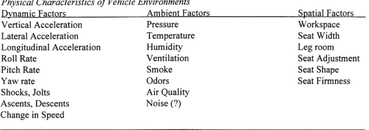
Comfort involves a sense of subjective well-being and the absence ofdiscomfort, stress or pain. Richards (1980). Discomfort means that the passenger is dissatisñed with the train ride. There are three different kinds of input: Physical, Social and Situational. In vehicle design and when you are interested in comparison of ride comfort or ride quality for different vehicles the physical inputs are most important. These factors are listed in Table 1.
Physical Characteristics of Vehicle Environments
Dynamic Factors Ambient Factors Spatial Factors
Vertical Acceleration Pressure Workspace
Lateral Acceleration Temperature Seat Width
Longitudinal Acceleration Humidity Leg room
Roll Rate Ventilation Seat Adjustment
Pitch Rate Smoke Seat Shape
Yaw rate Odors Seat Firmness
Shocks, Jolts Air Quality
Ascents, Descents Noise (?)
Change in Speed
Table l. Physical factors relevant for comfort. Richards (1980)
In a sense comfort is multidimensional in that it is the result ofjoint presence of all physical factors and discomfort arise when one of these factors are outside a specified range. The concept of vehicle ride quality appears to focus upon the vehicle but is actually a concept dependent upon the human passenger. It is a subjective judgement. Richards (1980). Normally ride comfort means comfort depending on variations of the physical dynamic factors such as accelerations, rate ofchange of accelerations (jerks) and angular motions.
The human perception of ride comfort is complicated. Many factors are integrated. The human perception of ride comfort in a steam vintage tour is very different from a business joumey. The technical evaluation of ride comfort is only a prediction under certain assumptions of what human evaluation of ride comfort could be.
Therefore, in a technical sense, ride comfort is a function of accelerations, jerks and roll motions of the vehicle. These factors are in tum 3 function of track and vehicle variables, speed, seats and other variables. This is shown in Table 2.
Table 2. Relations between different variables and ride comfort
Inputs (variables) Ride Comfort
Track/Vehicle Dynamic physic Technical evaluation Human evaluation {vk) vehicle {ai]» accelerations, jerks Ride comfort Q
{tk) track {(pi] roll, yaw Wz, ISO, CEN
{ok] other variables
as speed, etc. {ai, (pi) = f({vk, tk, okl) Ride comfort = g ({ai, (pil) f and g are functions
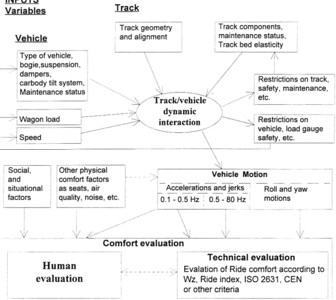
Another way of illustrating this is shown in diagram 2 below.
Schematic diagram over relations between VehiclelTrack interaction and Ride Comfort INPUTS
Variables
Tra°k
Track geometry Track components,
Vehic|e
and angnment
maintenance status,
_ I Track bed elasticity
Type of vehicle, \ /
bogie,suspen3|on, \
:gigant System, *\
\
Restrictions on track,
Maintenance status
\i
/7 safety' ma'ntenance*
/Track/vehicle \\///
etc'
; /øâz dynamic \ r . _ ,
\ / ! Restrlctions on
i
E /l Wagon 'oad
K \ \\_//interaction
/ N
; vehicle, load gauge_
i/
\
safety, etc.
T i l
\
SOCIal, Other physncal _ _ _ ü _:ä: Vehicle Motion
;and ,3 comfortfactors xa'å_ __ __ _ __ __T __ _ __ __. __E
; situational as seats, air l êgzeleiationsand _je_rks_f Ro" and yaw
factors
' quality, noise, etc.
in _ 05 Hz ; 05 _ 80 Hz
motions
%
i I : /1///4 \ I l ä i i /// \ i . l * /// : \
V
V Z
/// Å]\{
i/ \ Iv
Comfort evaluation| ,
i g
Technical evaluation
[
;
Human
5,-: ________ _ _ ;g Evalation of Ride comfort according to
evaluation
i \
WZ, Ride index, ISO 2631, CEN
1
i or other criteria
Figure 1. Schematic diagram over relations between Ride Comfort and vehicle/track inputs.
The structure ofthis research field is to try to isolate how different factors influence the ride comfort in the track/vehicle system. The motions in the car body are a result of how the vehicle and the track interact dynamically. For example track irregularities are transformed through the suspension system into the car body. If the car body has resonance at an unsuitable frequency, the passenger can be exposed to high vibration levels. Small variations in some vehicle and track parameters can influence the amplitude and frequency of acceleration and the ride comfort substantially. These motions and accelerations can be simulated by a vehicle/track interaction program. Examples of important parameters are rail and wheel profile, dynamic damping in track, track alignment, track gauge, track irregularities, long wave track irregularities, bogie suspension with Springs and dampers, speed etc. At the same time the vehicle must meetdifferent demands, regulations and safety rules. This is
illustrated in a schematic diagram (Figure 1).
1.1.1. Discomfort caused by vibrations above a frequency of 1 Hz.
In this area there are different standards of evaluating discomfort caused by vibrations. These standards are rather well establish. The first experiments were conducted in the early 1930's. For railway purposes Helberg and Sperling (1941) and Sperling and Betzhold (1957) proposed a ride
index called Wz (Werkungsziffer) (Obome 1976). The ISO 2631 "Guide for the evaluation of human exposure to whole-body Vibration" came 1972 and was mostly based on works by Miwa (1967) (Obome 1976). Later ORE conducted a series oftests and experiments in Question B 153 "Application of the ISO 2631 standard to railway vehicles" during 1981 - 1989. Today there is a
proposal from CEN TC/256 WG 7 "Ride comfort for passengers" (1993) for measurement and
evaluation of ride comfort. The main difference between evaluations according to ISO 2631 and CEN is that ISO calculate the comfort index on frequency weighted r.m.s (root mean squared) values of the acceleration signal but CEN uses a 95 quartile of 5 s r.m.s values of the frequency weighted
acceleration collected during at least 4 x 5 minutes. This also means that the ISO-evaluation of ride comfort (and also Wz) can be done in real time but the evaluation according to CEN has to be done after the test run.
But even if the ISO 2631 standard is well-establish there is serious criticism. D. J. Obome (1976) says
in the paper "A Critical Assessment of Studies Relating Whole-body Vibration to Passenger Comfort"
that "As there appears to be no study which may claim to adequately represent the levels of human reaction to Vibration, therefore, the conclusion must be reached that there is no one set of theoretical curves which have usefully drawn together the relevant research to quantify human reaction to Vibration". ORE has made contribution with Question B 153 rp 10 (1986) with laboratory experiments led by Griffin to get a better understanding of vibratory comfort
1.1.2 Discomfort caused by jerks and low-frequency accelerations and motions.
To my knowledge there are very few reports in this area. In 1983 - 84 BR conducted a number of tests with test persons equipped with push-buttons on high speed trains (HST) and tilting trains (APT). Harborough (1986). The test person was instructed to press the push-button whenever he or she felt a disturbance causing discomfort. The ORE in Question B 153 also carried out push-button tests. SJ and ASEA carried out similar tests during 1972 on the research train X15 when developing the tilting system. A similar test was carried out during 1992 on X2000 to confirm or revise the earlier results (SJ internal reports). SBB has also carried out tests with push-buttons for comparisons between a standard passenger coach, a coach equipped with a passive tilting bogie (Neiko) and an active tilting train (ETR 450). Wichser and Boesch ( 1993). The results from these tests do not correspond with each other. The advantage with the push-button technique is the directness between a test person's response and physical motion causing the disturbance. A major drawback is that the results may be effected by the test person's changing or not changing perception due to weariness or adaptation to ride environments.
1.1.3 Discomfort caused by motion sickness.
Also in this area there are few studies carried out or published on railways . One example is a study by M. Uenso et al on a Japanese passive tilting train (HCRSV type 381). He found that 59 % of the passengers asked, complained of motion sickness compared with 26 % in control trains. In almost all cases the passengers asked thought it was the pendulum motion that caused sickness. A frequency analyses showed strong peaks between 0.6 - 0.8 Hz in the tilting trains where the control train showed very small amplitudes.
Research on ships and laboratory experiments have shown that frequencies between 0.1 - 0.5 Hz are strongly correlated to motion sickness for vertical accelerations. Lawther and Griffin (1986) have proposed a standard for evaluating a motion sickness dose based on these studies. This standard does not include lateral acceleration or roll motions, which probably are of much importance in railway applications.
The current hypothesis is that "Motion sickness is a poison response provoked by motion. It is a poison response provoked by motion acting (directly or indirectly) on the vestibular system." (Money 1991) Treisman (1977). This means that in motion sickness situations the mismatch in sensory inputs
stimulates poisoning. Nausea and vomiting is the body's response to this poisoning. The question is -what kind of motion does invoke motion sickness? Treisman's hypothesis incorporates the earlier hypothesis of mismatch in sensory inputs. lt states that " All situations which provoke motion sickness are characterised by a condition of sensory rearrangement in which the motion signals transmitted by the eyes, the vestibular system and non-vestibular proprioceptors are at variance either with one another or with what is expected from previous experience." Griffin (1991 a), Reason and Brand (1975) and Benson (1988).
1.2 Measurement of Ride Comfort and Discomfort.
Ride comfort can be evaluated in many ways. One way is to ask test persons or passengers what they feel and how they judge the comfort or discomfort. Another way is to make measurements of
accelerations, jerks or other physical variables and from a specific standard calculate the ride comfort.
In most cases the railways uses the second approach, measuring ride comfort by measurement of accelerations. Different methods of measurement are described in appendix 1.
2. PROPOSED RESEARCH.
What has to be further investigated? It is of vital importance to establish a valid hypothesis about the
influence of low frequency motions on comfort disturbances. Based on such knowledge it will be possible to modify vehicle and track design that will minimise comfort disturbances.
The research project is divided into different stages with different aims and proposed activities. The aims and activities for a later stage are naturally dependent on the results and experience of earlier stages.
Stage l Aims:
o Establish hypotheses of causes of comfort disturbances due to low frequency motions. Methods:
0 A literature survey of comfort criteria and methods of determination of ride comfort. What kind ofmotions are important for comfort disturbances such as ride comfort, comfort disturbance due to low frequency accelerations and motion sickness.
o Contact and visit other research institutes and railway companies for discussion of comfort disturbances.
Stage 2. Aims:
o Establish methods for description and evaluation of comfort disturbances. o Establish methods for testing different hypotheses.
0 Determine the influence of different vibration and motion components (such as low frequency lateral accelerations, jerks and roll motions) for comfort disturbances.
0 Establish possible criteria for the evaluation of comfort disturbances caused by low frequency motions.
Methods:
0 Evaluate the low frequency motions and vibrations in high speed and conventional trains. 0 Develop an evaluation technique for measuring of comfort disturbances.
0 Make experiments in a drive simulator to rank different hypothesis ofcauses of comfort disturbances. (See proposed actions in simulator below).
0 Evaluation of covariance between expressed discomfort by test persons and measured vibration and motion components.
Stage 3. Aims:
- Check the validity of comfort criteria in high speed train environment Methods:
0 Test the most relevant hypothesis in a train with test persons for evaluation of possible criteria. (See proposed test in a train below).
0 Evaluation of covariance between expressed discomfort by test persons and measured vibration and motion components.
o Evaluation of Griffin concept of motion dose for prediction of motion sickness.
Possible stage 4. If this stage will be included it will be influenced considerably by the results and experience of earlier stages. Possible activities are:
a Investigate how different parameters for track and vehicle influence the comfort disturbances. o Suggestions of different actions to improve ride comfort and minimise the number of comfort
disturbances and passenger dissatisfaction.
2.1
Proposed tests in a simulator.
The VTI driving simulator is a half car built upon a platform which can rotate in roll and move on
rails to achieve lateral acceleration. In a simulator it is not possible to achieve a steady state lateral acceleration (for example in a curve) except through simulating it by a roll movement. Therefore, it is feasible to simulate curves as a vibration at a low frequency (0,2 Hz) to provoke comfort
disturbances.
It is proposed to test and rank the validity of different hypotheses for comfort disturbances (motion sickness). Are comfort disturbances strongly influenced by
- low frequency lateral acceleration, - roll speed or
- a combination of both lateral acceleration and roll motion?
2.2 Proposed tests on a train.
The results and the experience from the simulator will be used to alter and redefme the tests proposed to be conduced on the train. Parameters that can easily be varied is speed through the curves and the tilting angle. Therefore, lateral acceleration and roll speed can be varied to test the hypotheses that comfort disturbances are influenced by
- low frequency lateral acceleration only (no compensation), - roll speed only (full compensation),
- a combination of lateral acceleration and roll motion (partly compensation), - fixed roll angle with variable lateral acceleration or
- low frequency vertical accelerations.
Proposed tests will test the validity of the results from the simulator and a possible criterion. 3. RESOURCES FOR RESEARCH
The KTH (Royal Institute of Technology) is a major technical University in Stockholm. The
department of Railway is led by Prof. Evert Andersson, who has a background in the development of XZOOO. KTH also has a computer simulation programme for vehicle/track inter-actions to its disposal. The VTI (Swedish Road and Transport Research Institute) is a research institute with research in mainly in transportation, traffic, roads and railways. The VTI has a car driving simulator for behaviour studies and research. It is intended to use this simulator to test different hypothesis for comfort disturbances induced by lateral acceleration and roll motion. PhD H. Alm will be available for behavioural assistance and competence.
Contact have been made with MD L Ödkvist at the University Hospital in Linköping. He will be
available for medical assistance and competence
Johan Förstberg is a researcher with a Bachelor degree in Mathematics and Physics from Gothenburg
and a Master of Science in Measurement Technology from Linköping Institute of Technology . He has been working with the SJ Mechanical Laboratory for about 12 years. He was responsible for planning, conducting and reporting tests concerning ride quality, ride comfort measurement of forces between rail and wheel on railway vehicles. Two years ago he moved to the VTI, where he has been
working with questions concerning ride comfort and criteria for wheel-rail forces. He has also been
working on commission to SJ, The National Rail Administration (BV) and ABB.
4.
REFERENCES
Alm, Irma (1989). Transportabel komfort- komfortabel transport. VTI Rapport 347 (in Swedish).
Arvidson, A. and Andersson, T (1991). Jämförelse av olika kriterierför bedömning av
vibrationskomfort ijärnvägsfordon. KTH Dep. Railway. ISSN 0280-1078. (In Swedish. Comparision of different Criteria for Jugment of Vibratory Comfort i Railway Vehicles.)
Benson, A. J. (1988). Motion Sickness in Aviation Medicine, Second Edition. Edited by Emsting & King. Butterworths London, pp. 318 - 338.
CEN TC/256 WG7 (1993). Railway Applications. Ride Comfort for Passengers. Measurment and evaluation. 4 draft rev.
Griffln, M. J. (1990). Handbook ofHuman Vibration. London: Academic Press. ISBN O-l2-303040-4 Griffin, M. J. (1991 a). Physical Characteristics of Stimuli Provoking Motion Sickness in Motion Sickness: Signijicance in Aerospace Operations and Prophylaxis. AGARD Lecture series 175, Neuilly sur Seine.
Griffin, M. J. (1991 b). Sea Sickness in Motion Sickness: Signijicance in Aerospace Operations and Prophylaxis. AGARD Lecture series 175, Neuilly sur Seine.
Harborough, P. R. (1986). Passenger Comfort during High Speed Curving, Analysis and Conclusions British Rail Research BRR TR D08 017
Harborough, P. R. (1986). Passenger Comfort during High Speed Curving, Summary Report. British Rail Research BRR TR D08 018
Helberg and Sperling. (1941). Verfahren zur Beurteilung der Laufeigenschafen von Eisenbahnwagnen. Org. F.d. Fortschritte des Eisenbahnwesens 78 (1941), 12, p 176-187.
Irwin, A. W. and Goto, T. (1984). Human perception, task performance and simulator Sickness in single and multi-axis low frequency horizontal linear and rotational Vibration. Proceedings ofthe United Kingdom Informal Group Meeting on Human Response to Vibration, Heriot-Watt University, Edinburgh, 21 -22 Sept. 1984, pp. 289-315.
Kennedy, R. S. and Frank, L. H. (1986). Review of Motion Sickness with Special Reference to Simulator Sickness. Transportation Research record 1059.
Money K. E. (1991). Signs and Symptoms of Motion Sickness and its Basic Nature. Motion Sickness: Significance in Aerospace Operations ana' Prophylaxis. AGARD Lecture series 175, Neuilly sur Seine.
ISO 2631. Guide to the evaluation ofhuman exposure to whole-body mechanical vibrations.
Obome D. J. (1976). A Critical Assessment of Studies Relating Whole-body Vibration to Passenger Comfort. Ergonomics. Vol. 19, 6, Nov. 1976.
Oman, Charles M. (1988). Motion sickness: a synthesis and evaluation of sensory conflict theory. Can. J. Physiol. Pharmacol. Vol. 68,1990 pp 294-303.
ORE Question B153. (1986) Vibratory comfort. Drawing up weighting curves. Application ofthe ISO 2631 standard to railway vehicles. Rp 10. Utrecht
ORE Question B153. (1987) Comfort in standing position. Application of the ISO 2631 standard to railway vehicles. Rp 12. Utrecht
ORE Question B153. (1989) Comfort in seatedposition. Application of the ISO 2631 standard to
railway vehicles. Rp 17. Utrecht
Reason, J. T. and Brand, J. J. (1975). Motion Sickness. London: Academic Press.
Richards, L. G. (1980). On the psychology of passenger comfort. In Humanfactors in transport research. D. J. Obome and J. A. Levis (Eds.) Volume 2, London: Academic Press.
SJ internal reports: X15 report
LR 9210-15m. (1993). Mätningar av subjektiva komfortstömingar vid långvågiga spårlägesfel.(ln Swedish. Measurment of subjective comfort disturbances caused by long-wave alignment
irregularities)
Sperling and Betzhold (1956). Beitrag z. Beurteilung des Fahrkomforts in Schinenenfahrzeugen. Glasers Annalen, Okt 1956, p 314-317.
Trisman M. (1977). Motion sickness: an evolutionary hypothesis. Science 197: 493-495, july 1977. Ueno, M. et al (1986). Studies on motion sickness caused by high curve speed railway vehicles. Jpn J Ind Health 1986 : 28: 266-274.
Wichser, J. and Boesch, D. (1993). Die Druckknopfmethode, ein Hilfsmittel zur Erhebung des Fahrkomfortes. ETR 1993:42. H. Januar/Februar
Appendix l
APPENDIX
1. Mean comfort.
The mean comfort level is judged from accelerations in the frequency interval from about 1 Hz to 80
Hz. The upper limit can normally be reduced to 30 - 40 Hz without greater differences. The oldest ride
comfort index is the Wz or the English correspondent Ride Index. It uses frequency weightings (B(f))
drawn bySperling and Betzhold. It is still used by several railways. It gives a number between 1 and 5
with the following meaning.
Ride index Wz Comfort (vibrations sensitivity)
1 Just noticeable
2 Clearly noticeable
2.5 More pronounced but not unpleasant
3 Strong, irregular, but still tolerable
3.25 Very irregular
3.5 Extremely irregular, unpleasant, annoying; prolonged exposure intolerable
4 Extremely unpleasant; prolonged exposure harmful
(Garg and Dukkipati 1984) Calculation of Wz
T
Wz = 4.42*(1 / TI awzdt)]/6'67
0
where aW is the acceleration filtered by the Wz weighting filter B.
ISO 2631 "Guide to evaluation of human exposure to whole-body vibration" contains among other guides a guide for evaluation of reduced comfort boundary. The calculation of a ride comfort according to ISO is almost the same as the calculation of Wz.
T
150 = (1 / TJ (1,3de
[In/52]
O
where aW is the acceleration a filtered by the corresponding ISO weighting filter. The ISO filters are defined between l - 80 Hz. The Wz lateral and vertical weighting filters have both the same shape with a maximum between 4 - 6 Hz (only the magnitude is different), whereas the ISO-filters differ considerably. The principal differens between the different weighting filters are shown in appendix 2. Under the Questing B153 rp 10 ORE has made a laboratory experiment led by Griffin to extend the weighting curves down to 0.5 Hz. ISO 2631 draft 5. The weighting curves for ISO are under debate and revision.
Both Wz and ISO use a r.m.s value of the filtered signal for calculation of its value. This means that the result is an average and big peaks are levelled out. These big peaks can be very annoying to the passengers.
The CEN TC256/WG 7 "Ride comfort for Passengers. Measurement and Evaluation" proposal uses another way of calculating the ride comfort index. The weighting filters are the same as the ISO with modifications suggested by Griffin. The test run is divided into 5 min parts with constant conditions. These 5 min is split into 5 s periods where the r.m.s value is taken from the filtered acceleration. These 5 s r.m.s values are then statistically analysed. The 95th quartile (57 biggest ofthe 60 samples) is then
Appendix I
used for processing the mean passenger comfort value va. The Simplified formula for calculating va is:
va = 6 ( (awd, XP95)2 + (awd, YP95)2 + (awb, 21395)2 )O'5
where awd = acceleration a filtered by weighing filter d
XP95 = 95th quartile of histogram with values collected i X-direction etc.
There are also formulas for standing and seated persons. The assessment of these forrnulas has been done by ORE B153. 2. Discomfort caused by sudden motion and jerks.
This kind of discomfort can be tested by a number oftest persons pressing push-buttons. BR has done a number oftests with non-tilting and tilting trains in 1983-84. Harborough (1986). The results
identified two different situations where discomfort can arise. The first is discomfort caused by jerks in transition curves and the second is discomfort caused by discrete events such as sudden peaks in the acceleration level in full curves.
The CEN TC/256 WG 7 adopted these results. The calculation of discomfort levels according to CEN is straight forward but to find the physical values for the formula is rather complicated and is not well
suitable for computer evaluation. The discomfort level (PCT) in transition curve is based on the
maximum acceleration after the transition (y), the maximum jerk over one second (dy/dt) and the maximum roll speed (dB/dt). The physical values are found on the graph for each signal. The formula
is then ; PCT = my + B*dy/dt - c + owe/th
For discrete events the formula is PDE = a*y + b*ym - c, where yp is the peak to peak acceleration
over a period of 2 5 and ym is the mean acce eration.
The corresponding Swedish tests did not distinguish between curve transition or discrete events but instead focused on mean acceleration, low pass ñltered jerks (0.3 Hz) and roll speed. The results from the tests with the early test train X15 (1979) is a number of graphs showing an exponential increase of passenger discomfort with increasing acceleration and jerk but avery small linear increase with roll speed. The results from the tests with X2000 (1992) show a similar pattern for jerk but mean lateral acceleration was to low to show any response in discomfort. The main difference between the X2000 and X15 results, is that the sitting passengers are almost as sensitive as the standing passengers. This can probably be explained by the better general ride comfort in X2000 and much better track standard. In addition, today sitting passengers are expecting a higher level of comfort to be able to work and write. (SJ internal reports)
The push-button technique has advantages and drawbacks. It is possible to get an immediate response from the test persons but on the other hand the test persons have their own expectations about rail travel and comfort level.
3. Discomfort caused by motionsickness.
For motion sickness evaluation there is really only one method available for railway purposes, to ask the passengers. Certain low frequency motions seem to provoke motion sickness. This can be used as an indicator. The proposed ISO standard of predicting motion sickness is based on measurement of motion dose. It is defined by
Appendix I motion dose = (l aw2 dt) 1/2 [rn/31.5]
where aW is band pass (0.1 - 0.5 Hz) filtered vertical acceleration. Griffin and Lawther (1986) have shown that
vomiting incidence (%) 5 1/3 * motion dose
The formula is valued up to 70 % incidence and time between 20 min up to 6 hours. The authors also suggested a formula of predicting the average subjective rating of illness (O = "I feel all right", 1 = "I feel slightly unwell", 2 = "I fell quite ill" and 3 = "I fell absolutely dreadful")
illness rating _2_ 1/50 * motion dose
For railway applications it is necessary to find a model for combining lateral and vertical acceleration and roll motion.
Appendix 2.
Comparison between different weighting filters ISO 2631, ISO 2631 draft 5 and Wz.
Laterally: Figure 1 and 2.
Vertically: Figure 3 and 4.
: Hon'sontelh
1.0 "'
ru"
"' "°'
159 2631 dra" 5 Figure 1.
:
O's
'
2
---
:so 2631
0.4:
0.1 '5
1 I Y I ' I ' 1 H2
0.] 1.0 10 100
1.0 '1' --- ISO 2631 draft 5 Figure 2.
. ---- lSO 2631 C w M
0.41
0.1 '_
1 i I ' 7 ' I ' I HZ OJ 10 10 1001.0: ISO 2631 draft 5 Figure 3.