The influence of microstructural deformations
and defects on mechanical properties in cast
aluminium components by using Digital Image
Correlation Techniques (DICT)
Jahanmehr Armanjo
EXAM WORK 2012
Postadress: Besökadress: Telefon:
This thesis work, which is a part of the Technology master program in Product development and Materials engineering, has been carried out at the School of Engineering in Jönköping and in cooperation with SP Technical Research Institute of Sweden in the subject area Material science and engineering (influence of defects in cast aluminium components).
The author takes full responsibility for opinions, conclusions and findings presented.
Examiner: Professor Anders Jarfors
At department of Product Development and Materials Engineering
Jönköping University
Supervisor: Dr. Torsten Sjögren
SP Technical Research Institute of Sweden
Structural and Solid Mechanics
P.O. Box 857, SE-501 15 Borås, Sweden
Scope: 30 Credits
Abstract
Digital image correlation techniques (DICT), a non-contact deformation measuring technique based on gray value digital images, have become increasingly used over the last years. By using the DIC technique during a tensile test, the deformation behavior of different engineering material under an applied load can be determined and analyzed. Digital images, acquired from a tensile test, can be correlated by using DICT software and from that the local or global mechanical properties can be calculated. The local or global mechanical properties determination of a flat test specimens are based on the displacements or changes in a previous stochastic sprayed or natural pattern.
The used material for this purpose is cast silicon (Si) based aluminium (Al) component, designated as AlSi7Mg0.3 (Anticorodal-78 dv). The hypoeutectic Al- Si alloy is widely applicable for engine constructions, vehicle and aerospace constructions, shipbuilding, electrical engineering and constructions for food industry.
There are many microstructural parameters in a binary system Al- Si alloys, which the mechanical properties can be depended on, for instance phase distribution, Secondary Dendrite Arm Spacing (SDAS), morphology of Si particles (Roundness) and microscopic defects or pores. All these parameters can contribute to enhance the proper mechanical performance (e.g. Strength and ductility) in the Al-Si cast components.
Keywords
Al-Si cast alloys, AlSi7Mg0.3, strontium modification, heat treatment, SDAS (Secondary Dendrite Arm Space), Aramis, digital image correlation technique (DICT), mechanical properties (ultimate tensile strength, offset yield strength and elongation), plaster mould processes.
Acknowledgement
This thesis work is the final part of a two years Master of Science program in Product Development and Materials Engineering at Jönköping University of Technology.
The work has been carried out at SP Technical Research Institute of Sweden during the period of January 2012- September 2012.
I would like to express my gratitude to my supervisor Dr. Torsten Sjögren at SP Technical Research Institute of Sweden for his help and kind guidance during this project. Also many thanks to Professor Anders Jarfors, Dr. Salem Seifeddine at Jönköping University of Technology and other employees at both JTH and SP for their kind assistance and patience with me.
I would also give a special thanks to Assistant Professor Lennart Elmquist for his kind guidance and for inspiring me to choose this thesis subject.
I would like to thank my wife, daughter and parents who have continuously motivated and supported me during this period.
Content
INTRODUCTION ... 7
PROJECT BACKGROUND ... 7 PURPOSE ... 7 LIMITATION ... 8 DISPOSITION ... 8THEORETICAL BACKGROUND ... 9
CAST OF AL-SI ALLOYS ... 9 AL-SI ALLOYS ... 10 SILICON (SI) ... 12ESSENTIAL ALLOYING ELEMENTS ... 13
SOLIDIFICATION OF AL-SI ALLOYS ... 19
HEAT TREATMENT OF AL-SI ALLOYS ... 20
DEFECTS IN CAST AL- ALLOYS... 21
MECHANICAL PROPERTIES ... 22
DIGITAL IMAGE CORRELATION TECHNIQUE (DICT) ... 26
EXPERIMENTAL METHODS ... 29
SPECIMENS PREPARATION AND VARIATIONS ... 29
TENSILE TEST ... 31
MACRO STRUCTURE ANALYSIS (ARAMIS) ... 37
TEST DEVIATIONS ... 38
RESULTS AND DISCUSSION ... 39
GLOBAL MECHANICAL PROPERTIES ... 39
MECHANICAL PROPERTIES OF LOCAL CONDITION (MICRO) ... 44
CONCLUSIONS ... 48
FUTURE WORK ... 49
REFERENCES ... 50
Introduction
Project background
All cast components have defects as a drawback of the casting process. Even cast Al-Si components contain different defects on a macro and microstructural level. It is well known that mechanical performance and properties in cast Al- Si components (e.g. strength, ductility) will change due to different chemical compositions and casting conditions. By tensile tests in combination with Digital Image Correlation techniques (DICT) it is possible to get an idea of the degradation mechanisms by comparing their mechanical properties like strain, offset yield strength or ultimate tensile stress with different defect fractions.
The goal of the present project is to study the materials microstructure in situ by using tensile testing method. During the tensile test microstructure images can be gathered and from these macro and microstructural strain-field, Yield strength and Ultimate Tensile strength of the specimen calculated and generated by using DICT, which could give an indication of how stress and strain are accommodated by different phases or concentrated by porous defects (Porosity).
Purpose
Different defects like porosities, entrained oxide films, metallic inclusions and phases, could affect the mechanical properties of cast Al- Si alloys. In order to determine the degradation effect of defects on mechanical performance, tensile specimens with various defects and defect fractions from commercial plaster mould cast Al- Si alloy components were made. All specimens used in this study had the same chemical composition (AlSi7Mg0.3), known as commercial Anticorodal-78 dv (Si based hypoeutectic Al- Si alloy). They only differ in their microstructure due to T6 heat treatment or Strontium modification of the specimens. In order to examine these specimens tensile test on macro and microstructural level were used and during the tensile tests, images were acquired. By using Digital Images Correlation technique (DICT), it was then possible to calculate the local and global strain-field. To investigate the influence of different defects on mechanical behavior is the main purpose of this thesis work.
Limitation
The thesis work is part of an ongoing research project performed in collaboration with an industrial partner. It is limited in time to 20 weeks of fulltime work and one material composition of Al-Si alloy (AlSi7Mg0.3) with four various microstructural conditions regarding their mechanical properties will be investigated and analyzed.
Since the chemical composition of Anticorodal-78 dv (Table 2) are within the hypoeutectic range of Si based Al- alloys (AlSi7Mg0.3), it will be appropriate to mainly focus on the microstructural and mechanical properties of hypoeutectic Al-Si alloys and their additional alloying elements This work will neither develop new materials for Si based Al alloy cast components nor new modification or casting methods. It will cover the most considerations and discussions around Al- Si hypoeutectic cast alloy (Anticorodal-78 dv) in its variations, defects, their mechanical properties and microstructure conditions. Al-Si hypereutectic cast alloys and their general chemical compositions or different casting methods and possible detrimental conditions during casting and their comparisons will not be discussed due to predetermined casting process and 2conditions. The plaster molding and their possible advantages or disadvantages will be not included in it.
The only modifier which is used in this study is strontium (Sr). Besides stress/strain, elastic- plastic- behavior, standard tensile testing and DICT, all other mechanical behavior or testing methods (hardness test) is not subject of this project.
Disposition
The report contains discussions in theoretical background regarding definitions and descriptions of cast Al- alloys, strontium modification and T6 thermal treatment of AlSi7Mg0.3 alloy in general and will then discuss the essential alloying elements and their chemical reactions and bonds with effects of defects on Al-Si microstructure and mechanical properties.
Theoretical background
Cast of Al- Si alloys
The casting process can be described as a shaping process. A desired final shape or form with different properties can be achieved by pouring any molten material including Al- Si alloys into a prepared cavity or mould in one single step [1, 2].
Generally in casting process, there are few sequences and stages like melting of material and optional treating to modify the chemical composition (e.g. Inoculation, Grain refining), Filling or pouring of molten material into a cavity or form and Feeding and solidification (Nucleation and growth). Casting can in general be divided in two subgroups as expandable and multiple-use mould. (figure1.1)
Figure 1.1:schematic overview of the casting family with subgroups [5]
The selection of suitable casting method is dependent on quality requirement or performance, technical boundaries or limitations as well as the economic aspects. Because of the high shrinkage during the solidification and sensitivity to hot cracking, pure Al is seldom cast. Al-Si alloys on the other hand can be cast by various processes and in higher quantities and nevertheless the casting characteristics remain stable and strength can be improved. Also regardless the expendable or multiple-use mould casting, Al- Si alloy becomes very suitable for this kind of shaping process due to its low melting temperature [2, 3].
mention this method as follow:
In plaster molding, slurry of plaster of Paris is poured over a pattern contained within a mould box. It takes 10-20 min to remove the pattern after the plaster sets. In order to remove the water before casting, the rigid mould rests at an elevated temperature until drying. The casting must be conducted by using vacuum or pressure assistance due to impermeable mould. The tooling costs are, in comparison with other casting processes, modest and rigid patterns could be made of wood, plastic, metal or plaster as well as urethane for flexible patterns. The low thermal conductivity and cooling rate could generate uniform grain structure. Castings with smoother surface, finely reproduced detail and greater dimensional accuracy can be achieved. [3]
Al- Si alloys
Al- Si alloy is one of the most commonly used materials for producing low-density components with less economical efforts. Because of the poor properties, pure Al is seldom used in cast components. By adding small amounts of alloying elements i.e. Silicon, Copper, Magnesium, the pure Al can be enhanced [1]. By using Al-Si alloys, it is possible to produce critical cast components with complicated shapes and good mechanical behaviors (i.e. ductility and strength). Thus they can be widely applicable for instance in automotive or aerospace industries.
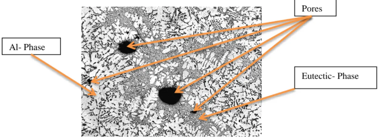
Figure 2.1: Illustrates the typical microstructure of Si based aluminium alloy with the α- phase (Al- phase), β- phase (eutectic phase) and some pores with 200μm magnification.
The limited solubility of silicon in aluminium or vice versa, limited solubility of aluminium in silicon is typical for the simple binary eutectic, hypoeutectic or hypereutectic Al- Si system. At the eutectic temperature, the solubility of silicon in aluminium reaches maximum value of 1.65 wt% and even increases to 0.016% Si at 1190°C. [4, 5]
Eutectic- Phase Al- Phase
Figure 2.2 demonstrates the occurrence of hypoeutectic reaction for AlSi7Mg0.3 alloy (Anticorodal-78 dv) with 6.5-7.5 wt % and eutectic reaction with 12.6 wt% Si at 577◦C on the binary phase diagram.
Figure 2.2:Depicts the Al-Si binary phase diagram [4]
Enough content of Si as an additive gives the pure Al the ability to produce the outstanding eutectic reaction which can be characterized through a low melting point and high strength. Furthermore, Si as an alloying element can provide excellent casting properties like good feeding characteristics, high fluidity, good cast ability, shrinkage reduction, proper thermal conductivity (150-170 [W/ (m.K.)]), cracking resistance, higher strength/weight ratio, excellent surface, wear resistance and good tensile and fatigue properties. Al- Si alloys usually obtain suitable casting characteristics with an improved strength and therefore it is possible to cast Al- Si alloys in considerable quantity and variation of processes. [2, 3, 4, 5]
β= Al- Si Eutectic α= Al
Silicon (Si)
Adding Si into Al forms a eutectic system as the Al-Si binary alloy. Dependent of chemical composition and microstructural properties, Al-Si can prove high ultimate tensile strength, wear resistance, good machinability and castability due to decreasing effect of Si on thermal expansion coefficient of Al-Si alloy [5].
Because of the narrow freezing range of Si, low viscosity can be achieved, which provides excellent fluidity of Al-Si alloys. Due to low density, Si can be added into Al without any impact on alloys weight. Adding more than 13% Si reduces the volume shrinkage in alloy but decreases the machinability at the same time. The low shrinkage of alloy makes it resistance to hot tearing and performs outstanding weld properties and soundness. Si content can provide better corrosion resistance property, since Si as non-metal alloying element in the Al-Si eutectic does not respond to most environmental impacts. With Increasing Si content, porosity can be even decreased in Si based Al- alloy [4, 6, 7].
When the solidification sequence of Al-Si alloys starts, both primary Al (dendrites) and Si phase (angular primary particles) form and grow. At the eutectic point on the other hand, the eutectic Al-Si phases nucleate and grow until the end of this sequence (Figure 2.2). When room temperature is reached, hypoeutectic Al- Si microstructure consists of primary Al- phase and eutectic Al- Si. In general, Al-Si alloys with evenly distributed finer circular particles or grains perform higher ductility in contrast to acicular coarse grains which perform higher strength. Thus the more Si content, the higher the stiffness, hardness and ultimate strength but less elongation can be registered in Al-Si alloys [1, 6, 7, 8].
The mechanical properties of cast Al- Si alloys are directly dependent on the microstructural performance which depends on metallurgy, treatment and certainly their chemical composition. For instance the increased ultimate tensile strength by decreased grain size decreased SDAS by increased rate of cooling or the compensating behavior of alloying elements during the solidification sequences [1, 3, 9]. (Figure 2.3)
Applicability of alloys relies also on the mechanical and physical properties which in their turn are dependent and sensitive to microstructural variations of cast Al- Si alloys [6]. (I.e. density, melting point, optical properties, thermal conductivity, permeability, electrical properties and etc. of all materials are influenced by the microstructure. Below are some of the considered parameters which are determinant for microstructure in Al- Si cast alloys and their related mechanical properties:
- Chemical composition (Si based Al- alloys and alloying elements) - Distribution of Phases (α-Al and Al-Si eutectic)
- Primary α-Al morphology (α-Al dendrites) - Al-Si eutectic morphology (e.g. Roundness) - Secondary Dendrite Arm Spacing (SDAS) - Rate of solidification or cooling
- Microstructural pores
- Impurities and microstructural defects
Essential alloying elements
The variation of Al- Si alloys selectable for casting is very large but generally they are divided in two main categories as primary and secondary Al- alloys. The iron content or other impurities determine the difference between these two classes. The secondary alloys contain a higher level of iron, which is considered as impurity for most purposes. Due to impurity in the secondary alloys, they are usually cheaper to purchase than the primary alloys but even secondary one can perform mechanical properties as good as the primary alloys.
One common alloying element in Al-Si alloys is copper (Cu), which is forming either aluminium- copper rich phases (intermetallics) such as Al2CU or found partially dissolved in the dendrite matrix. After the main Al-Si eutectic reaction, intermetallics will be solidified in one massive and one fine eutectic form. The Strength and ductility of these alloys are substantially dependent on presence of Cu either in solid solution (equally distributed spheroidised grains) or continuous network at the grain boundaries.
Alloys with dissolved Cu in the matrix retain ductility and proves increased strength. A continuous network of Cu at the grain boundaries improves the strength to the appreciable level but decreases the ductility at the same time. Nevertheless, an increase of Cu content in the alloy increases the hardness but also porosity formation will increase. It is comprehensible that the modulus of elasticity of Al- Si alloys is proportional with Cu content. [1, 8, 10]
Magnesium (Mg)
Magnesium (Mg) is a common alloying element which occurs either as principal alloying element or as impurities in Al- Si alloys. Mg is highly responsive to other elements and develops inclusions and intermetallic particles. Therefore it should be considered to limit the Mg level in Al- alloys. For instance Mg can react with oxygen and oxidize in the melt, which results in MgO particles (micrometer size). On the other hand Mg might react with the other existing elements in an alloy, which can result in intermetallic particles like; Al8FeMg3Si6 and Cu2Mg8Si6Al5. It is also well known that all these intermetallic particles and inclusions have degrading impact on the overall properties and as well affect the fluidity. Nevertheless, the mechanical properties of Al- Si alloy, which are likewise sensitive to grain size, prove high strength and proper ductility. (Figure 2.4)
The higher Mg content in an alloy, the higher hardness, strength and fatigue resistance values but also the ductility will suffer and decrease as a drawback. [1]
By adding a proper amount of Mg into Al-Si alloy, an improvement of heat treatment capability of the alloy can be achieved. Once the alloy is solution treated upon aging, due to the fact that Mg and Si dissolve in the Al throughout the treatment, highly dispersed Mg2Si particles will appear in the matrix. This occurrence significantly influences tensile strength, yield strength and ductility of the alloy. It should be mentioned that heat treatment cannot develop its strengthening effect, when in Al-Si alloys; coarse particles are formed with Mg (as Mg2Si) or even with Cu (as Cu2Mg8Si6Al5). In order to get the better heat treatment response from Al-Si alloys, it is reasonable to assign a limited amount of Mg into an alloy.
AlSi-Mg alloys possess an excellent corrosion resistance due to specific volume of the formed oxide film layer, which provides high impermeability [1]. The castability of Al- Si alloys is very poor by lower contents of Mg (Mg≤ 4 wt %), however it can be slightly improved by Mg content higher than 7-12 wt%. They provide excellent surface finish and have good weld ability but also a tendency to hot tears (wide freezing range), inclusions (strong response to other elements). Because of the fine dispersed particles in these alloys the fluidity is as affected.
Figure 2.4; illustrates the influence of Mg content on the mechanical properties of an Al-Si alloy [1]
Iron (Fe)
In general iron (Fe) is always found in commercial Al- Si alloys. It can unintentionally participate or may join the alloys due to the use of steel based casting tools or during melting of alloys. Also usages of remelted materials cause the participation of Fe or rust into the Al- alloys. Because of the detrimental effect of Fe on Al- Si alloys, it is reasonable to keep the Fe content of Al- alloys as low as possible, if economically approved.
effects of Fe depend significantly on the morphology of the formed phases. In a binary Al-Fe system, the balanced solid solubility of iron in Al is about 0.03-0.05 wt% at the eutectic temperature (655 °C) and decline by decreasing temperature down to room temperature. The phase, which is usually present in steady state with Al, is commonly characterized as FeAl3 (40.7 wt%, Fe) but there are also several ternary phases, which can be in steady state with Al in an Al-Fe-Si system with high Si content like; Fe2SiAl8 (α),FeSiAl5 (β), FeSi2Al4 (δ) phases. Al-Fe-Si systems as well with high Fe and Si alloys can reach the steady state with Al as FeSiAl3 (γ) phase. However, due to non – equilibrium solidification of most casting, it is not unusual to find alloys in which FeAl6, FeAl3, Fe2AiAl8, FeSiAl4 coexist with each other and with Si.
Whenever Cu is available in Al- Si alloys, the Al-FeSiAl5-Si occur as acicular needle shaped eutectic. Alloys with Mg, Cu, or Zn and FeSiAl5 (primary crystal by Fe≥0.8 wt %) may appear as Chinese script. The FeMg3Si6Al8 might be formed as Chinese script
(eutectic) or as globules (primary) due to presence of Mg, On the other hand, Iron in reaction with Mn , forms the Al15(Fe, Mn)3Si2 in Chinese script shape and removes the brittleness of the needle formed FeSiAl5.
Since the Chinese script shape is less detrimental to the tensile properties of alloys than the brittle needle shape, it is preferable to shift the Fe bearing phases (needle form), where their grain size and morphology are very dependent on alloy composition and casting conditions, into the Chinese script. There are several elements, which act as Fe corrector (e.g. Mn, Cr, Ni and Co).
Adding Chromium or Nickel might reshape the Fe phases but also cause brittleness, due to elongated shape. Cobalt on the other hand seems to be a better Fe corrector but is not combinable with Si and therefore forms limited particles in Al- alloys.
The corrosion resistance of an alloy is reduced by an increase of Fe amount, especially galvanic corrosion. Furthermore, the Fe crucial phases decrease the ductility of the alloy but increase its hardness. Resistance to hot tearing increases at a certain amount of Fe and the tendency for soldering and die sticking reduces in Al die casting alloys as well as solidification shrinkage of Al- Si alloys [10].
Manganese (Mn)
The high temperature properties of Al-Si alloys and fatigue resistance can be
insubstantially improved as well as reducing of shrinkage. Whenever Mn is available in alloys, it has the compensating task regarding the detrimental effects of Ferrous by reshaping the compound Al15(Fe, Mn)3Si2 into Chinese script. Needle shaped Fe phase (FeSiAl5) with embrittling effect can be also minimized [1].
Nickel (Ni)
Nickel presence in Al- Si alloys influence the strength of alloys and has the increasing effect on ductility, as long as it appears as Fe corrector in Al- alloys. The opposite will occur, if Ni does not act as a Fe corrector and may reduce the ductility [1].
Chromium (Cr)
As mentioned before, Chromium has almost the same characteristic as Nickel and acts also as Fe corrector. The increasing content of Chromium in Al-Si alloys might reduce the ductility of alloys [1].
Zinc (Zn)
When Zinc is available in Al-Si alloys, the high temperature strength will decrease and prove an increasing hot tearing tendency. The machinability and corrosion resistance of alloys will improve due to compensate task of Zn for Cu and Ni [1].
Effect of impurity elements
Certainly there are many common alloying elements which can be intentionally added into Al casting alloys to improve the all-round properties and performance of alloys, but also undesirable impurities can occur in alloys. Due to low concentration of impurity
elements, which are available in most commercial Al casting alloys, the impurities dissolve in the Al and their influence on Al- alloys property is negligible. Only under some
circumstances, intermetallic compounds may occur, which may appreciably affect the properties and performance of Al- alloys.
The shape of Al- Si eutectic is determinant for mechanical properties of the Al-Si alloys. Proper eutectic modification of Al-Si alloys becomes more crucial than the grain refinement regarding the casting and mechanical properties of alloys. Changes in the morphology of Al- Si eutectic can be interpreted as a kind of modification. Since the formed Al- Si eutectic in an unmodified Al-Si alloy appears as a coarse flake-like structure, which ensure brittleness and degradation in mechanical properties of Al-Si alloys, therefore it is desirable to reshape the Al- Si eutectic structure shape from coarse to more fibrous fine flake structure in order to improve the mechanical properties of Al-Si alloys. (Figure 2.5 and 2.6)
Figure 2.5: Non modified AlSi7Mg0.3 alloy microstructure with a flakes formed eutectic structure [4]
Figure 2.6: Modified AlSi7Mg0.3 alloy microstructure with a fibrous or more round formed eutectic structure The modification is possible by the introduction of a low concentration of specific elements such as Strontium (Sr), Sodium (Na) or Antimony (Sb). The modification fulfills refinement and redistribution of Si- phase, which leads to improvement of the mechanical properties in Al-Si alloys.
There are two types of modification, which are applicable in most foundries; quench modification by rapid freezing or chemically induced modification, which includes addition of specific alloying elements. In quench modification, the rapid freezing induces twinning in the growing Si crystal lattice and the growth direction of the crystal lattice might be forced to change several times and results in a fibrous or branched structure. By chemically induced modification, the modifier inhibits the growth of the eutectic silicon phase which nucleates on the primary aluminium dendrites during the solidification of Al-Si alloys. Also the refinement and consistent distribution of Si crystals improves the ductile behavior of Al-Si cast components, since the mechanical properties of Al-Si alloys are strongly dependent of the morphology of Si particles. [11, 12, 13]
In this case, the chemically induced modification of AlSi7Mg0.3 alloy with strontium results in transforming the morphology of Al- Si eutectic phase from plate like in to fibrous one. It is as well mentionable, that adding of strontium in higher level than needed (over modification), leads to reduction of the Al-Si alloy properties as well as coarse Si structure and the strontium will interact with intermetallic phases. [4, 12, 13]
Solidification of Al- Si alloys
Generally a phase is the homogeneous region of a system and the solidification in a system can be described as a phase transformation [14], e.g. the transformation from a liquid phase in to a solid phase. In the case of Al-Si hypoeutectic binary system alloys the two main phases or alloying components, which the solidification microstructure consist of, are Al and Al- Si. The solidification microstructure shape can be considered as dependent on alloy composition, cooling rate and also their two basic growth morphologies (dendritic (α- phase or primary Al-phase) and eutectic (β-phase or Al-Si phase) growth morphology), which exist during the Al-Si alloy solidification [14]. (Figure 2.7)
Figure 2.7: the Al-Si alloy’s microstructure containing primary α-Al and Al- Si-eutectic phase [13]
During solidification there are generally three zones with different behaviors at the mould/metal interface. The cooling rate at this site is the highest, due to the large temperature difference between mould wall and melt. The sudden heat exchange between these two sites causes the formation of many randomly oriented small grains as well as its nucleation at the mould surface. Thus an outer equiaxed zone is created and the grains start to develop arms and become rapidly dendritic shapes, which grow along the preferred crystallographic directions. The competitive growth behavior between the randomly oriented grains, which has the preferred growth direction, causes the parallel alignment and directional opposition of grains to each other in order to eliminate others. The higher growth rate of outer equiaxed grains allows them to overcome the solid/liquid interface morphology, which provides the characteristic columnar zone (Figure 2.8).
Si morphology in dark
grey color α- Aluminium morphology
microstructure phases or sites known as primary Al and Al-Si eutectic include in Al-Si alloys. The mechanism during solidification includes nucleation, growth and evolution of the primary Al and Al-Si eutectic in an unmodified or modified system. The local form of solidification, microstructure and properties govern the global one as well as the related mechanical properties in the Al-Si alloys.
The two mentioned morphologies (dendritic and eutectic) exist through various stages from nucleus to grain during the equiaxed solidification. The single phase nuclei in each case forms initially. This means that the nucleus grows into the dendritic formed grain from spherical crystals and these dendrites finally merge into each other by continuous growth [14].
The first growing nucleus during the cooling and solidification of Al-Si alloy is the Al dendrites, where the primary solidification starts after cooling from the pouring temperature. The nucleation and growth of eutectic grains (Al-Si solution) starts directly after the Al-dendrites has started to form. Growth of two phase’s in the eutectic grains and cooling after the solidification occur simultaneously in the following stages and in a spherical form. Si appearance in eutectic grains is with non-metal properties and directed covalent bonds and shows the tendency to grow isotropic into faceted crystals.
Heat treatment of Al-Si alloys
The often used heat treatment of Al-Si alloys is the T6 processing which mostly consist of solution treatment at temperature close to the solidus temperature, quenching and ageing at temperature range between 160°C to 200°C. To be able to heat treat the Al-Si alloys, it is necessary to add some precipitation hardening particles to the alloy and even the significant decreasing solubility of the precipitants by decreasing temperature can contribute to better response to heat treatment. One of the very common precipitation hardening elements is Mg, which in reaction with the Si content in the alloy, forms to Mg2Si. The solution treatment is generally based on dissolving of precipitation hardening particles into the Al constituent or with other words between the atoms boundaries into a solid solution of atoms. This implies temperature increasing and holding of the higher temperature for longer time in order to achieve more homogenous solid solution or structure. [7]
The next step in order to keep the precipitation particles in the matrix is the sudden temperature decrease with water (often used quench medium), known as quench operation. After the quench operation follows the ageing operation, which can be considered as the last step in the T6 processing. The ageing of Al-Si-Mg alloys includes temperature raise up to 155°C-175°C and keeping the temperature in this range for about 4-6 hours. Ageing as the final step in T6 heat treatment process will take away the precipitation hardening, which
is Time and temperature dependent. Deviations in these two important parameters in ageing could contribute to over ageing or degradation of material properties otherwise by implementing the proper parameters; the mechanical properties can be improved. It is possible to enhance the mechanical properties of Al- Si alloys due to microstructural changes during the solution treatment, quenching and especially ageing by take away precipitation hardening [7, 14].
Defects in cast Al- alloys
In general microstructural features or microstructure constituents, which somehow have detrimental effects on mechanical properties, can be considered as defects in Al- Si alloys. The most common Al- alloys contain Si, which improves the fluidity as well as performance of the eutectic reaction in Al-Si alloys. This higher degree of fluidity in cast Al-Si alloys for instance is required in order to have the ability to cast complex geometrical shapes with varying section thickness. Besides the fluidity or composition of Al- alloys, there are several other variables, which the alloys are sensitive to regarding their casting characteristics and formation of casting defects. Also mechanical properties of Al-Si alloys are obviously directly dependent to these various futures such as composition, modification, grain size, solidification, Hydrogen content, mould conditions, mould filling, pouring conditions, hot spots, casting design, casting process, treatment, mould design, turbulence, contaminants, sludge, cooling rate, feeding and shrinkage conditions, etc. (Table 2.1).
Table 2.1: Some of the general common defects, which are related to the mentioned variables in Si based Al- alloys
C o m p o sitio n Mo d if icatio n Gr ain s ize Mo u ld C o n d itio n Hy d ro g en Ho t sp o ts C asti n g d esig n C o n tam in an ts T u rb u len ce Slu d g e Fu rn ac e C asti n g Pro ce ss Po u rin g co n d itio n s Micro cracks X X X Gas Porosity X X X Surface defects X X Leaker porosity X X X Inclusions X X X X Shrinkage porosity X X X X X Hot tears X X X
Casting defects like porosity and inclusions are the most commonly observed defects in cast Al-Si alloy s. Microstructural Pores emerged from gas, shrinkage or leaker porosities are the most common type of defects. Pores are not able to sustain external loads and have a huge degradation impact on mechanical properties, which is caused by the reduction in effective area by pore volume fraction and stress concentrations around pores. Thus they initiate and propagate micro cracks in the microstructure.
Gas porosity
Generally gas porosity can be described as trapped gas in casting. In Al- alloys, gas porosities are caused by hydrogen, which occurs due to reaction of molten Al with moisture in the melting environment. The solubility of Hydrogen in Al increases, when Al reaches its melting point and Hydrogen develops its maximum solubility above the Al melting point. Vice versa, the solubility of Hydrogen in Al alloys decreases by decreasing temperature. During the solidification Hydrogen bubbles nucleate and grow and reach its minimum solubility in solid state of Al. Thus Hydrogen as the only gas with measurable solubility in molten Al can cause the spherical formed porosity in solidified cast Al- alloys if it comes to impound throughout casting.
Shrinkage porosity
Generally, the internal cracks in casting can be described as shrinkage porosity. This type of porosity has got different sources but mainly they appear due to very thick wall sections in cast components. As mentioned before, during the solidification, first the primary Al dendrites start to grow until they crash to each other and the dendrites mobility is restricted. Interdendritic feeding, which involves the eutectic liquid flow, occurs then in order to compensate the shrinkage. Shrinkage porosity will appear, when interdendritic feeding can’t compensate the volume contractions in the dendritic regions.
Inclusions
Iron is the most unwanted and detrimental impurity in Al-Si cast alloys. The liquid solubility of Iron in Al casting is high but in solid state and at the room temperature quite low. Fe content reacts mostly with eutectic phase and creates a brittle, hard iron-rich intermetallic compound (Al5FeSi), which is detrimental for the material properties. Because of the plate shape of eutectic phase, which participate in the iron-rich intermetallic compound, it can be considered, that these plates could act as a stress raiser and initiate cracks and also lead to increased porosity , due to block of interdendritic feedings channels [7, 12, 13].
Mechanical properties
In the case of Al-Si alloys, the mechanical properties responds to microstructural changes like phase distribution (α-Al and the Al-Si eutectic phase), grain size and shape, amount and content of other alloying elements including Si morphology, impurity level and crystal structure type. These variables can in their turn be controlled by the casting process, cooling rates, solidification process and different refinements like modification or thermal treatment in Al- Si alloys [2].
By comparing two of the casting processes like gravity die casting and sand casting and according to the standard EN AC- 42100 for AlSi7Mg0.3 (T6 treated) and EN AC- 42200 for AlSi7Mg0.6, it can be seen, that gravity die casting proves UTS and the yield strength
of AlSi7Mg0.3 but also affect the ductile properties with degraded elongation. Also an increase in Si contents delivers obviously degraded mechanical properties [15]. (Table 2.2) Table 2.2: Illustrates the changes in mechanical properties of AlSi7Mg0.3 (Anticorodal-78 dv) in accordance with EN AC- 42100; Shows the
changes in its mechanical properties is obviously dependent on the type of casting process (GDC or SC). [15]
Casting method Numerical alloy description Chemical symbols Material condition Avg. UTS [MPa] Avg. Yield strength [MPa] Avg. Fracture strain [%] (A50mm) Gravity Die Casting EN AC-42100 EN AC- Al Si7Mg0.3 T6 ≤ 295 ≤ 215 ≤ 4,5 Sand Casting EN AC-42100 EN AC- Al Si7Mg0.3 T6 ≤ 275 ≤ 195 ≤ 7
Strain properties
The strain properties of Al-Si alloy is very dependent on the Mg and Si content as alloying elements as well as amount of Fe as impurities. For instance, Fe contents greater than 1% could result in decreasing of Ԑfr [mm or %], (strain at the fracture) [16]. (Figure 2.9)
Figure 2.9: Demonstrates the influence of Fe content on the mechanical property of [18]
On the other hand, size and morphology of Si particle will influence the ductile property of the alloy. [16, 17] The fibrous the shape of the Al Si eutectic phase (β- phase) and the better the distributed phase, the ductile the Al-Si alloy and vice versa, by needle shaped β- phase, the ductile property decreases[18]. By modifying the Al-Si alloy, the elongation can be enhanced due to changes in the shape of the β- phase (from needle to fibrous shape). The ductile behavior of the alloy can also be determined due to solidification rate of the cast Al-Si alloy. An increase of cooling rate will decrease the secondary dendrite arm spaces in the alloy, which will degrade the ductile performance but increase the tensile property of Al-Si alloy.
Yield tensile strength
Most of the Alloying elements like Mg, Cu, Mn and Zn has an increasing effect on the tensile yield strength in the Al- Si alloy. [19] Of course dependent on casting method, the amount of the alloying elements (table 4) will determine the level of the tensile yield strength in cast alloy. For instance, by increasing the amount of Mn content up to 0.5%, the tensile yield strength (σ yield [Mpa]) of the die cast Al-Si alloy will be improved [15, 22].
Especially the amount of Mg and Cu content has greater influence on tensile properties and enhance the Al-Si alloys tensile yield strength than the amount of Mn and Zn content in the die cast Al-Si alloy. [23] Even the amount of Fe content higher than 0.2% proves improved σ yield in Al-Si alloys. [21] Other main alloying elements amount like Si, Mg and Sr of content will affect the tensile yield strength due to participation hardening by decreasing these alloying elements shape and morphology [20].
It is proper to mention the effect of cooling rate on the σ yield; once the cooling rate increases, the σ yield of the Al-Si alloy will prove higher values.
Ultimate tensile strength
UTS [MPa] respond on the solidification rate is high and the UTS [MPa] is so with dependent on the Secondary Dendrite Arm Spaces or SDAS. The smaller the spaces between the secondary dendrite arms, the higher the tensile strengthen performance, which on the other hand could be achieved by increasing the solidification rate of the cast Al-Si alloy. [24]
UTS [Mpa] in Al-Si alloys is also very much dependent of Si content in the cast alloy. Si contents from 5 to 20% increases the UTS between 250- 350 [Mpa], [25]. Also Mg as the other alloying element proves increasing effects on UTS. At the other hand, contents more than 1% of Fe as an inclusion or impurity (β-AlFe5Si phase) proves decreasing effect on UTS [Mpa]. [18]
Figure 2.10; compares the UTS [Mpa] of various Si based Al alloys with different composition of alloying elements (e.g. CU, Mg) at the presaging temperature. [16]
By looking at other alloying elements in Si based aluminium alloys, it is fact that for instance Cu content up to 1.5% will increase the UTS due to participation of main Cu bearing phases (θ-Al2Cu) in the inter dendrite spaces and also may at the same time decrease the UTS due to porosity effect in the alloy [22]. (Figure 2.10)
Even addition of Mn will neutralize the high Fe content in Al-Si alloy, which will results in enhanced tensile strength. [26]
SDAS and mechanical properties
The solidification rate of the Al-Si cast alloys can often be measured by using the dendrite structure of the desirable cast Al- alloy. [7]
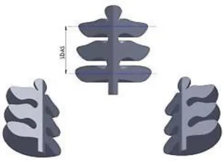
Figure 2.11:Secondary Dendrite Arm Spacing (SDAS), the picture was generated only for the purpose to define SDAS
Figure 2.11shows a α- Al dendrite arm and the graphical definition of Secondary Dendrite Arm Spacing, known as SDAS, which is the most common parameter in order to evaluate the cooling rate during the solidification [30]. The distances between the α-Al dendrite arms (variation from 10-15 µm) are dependent of mold material, casting thickness, methods and cooling rate in casting. [7]
Increased cooling rate results in decreased SDAS which in its turn enhance the distribution of alloying elements inside the aluminium matrix in cast Al- Si alloys. The distances between the secondary dendrite arms in alloy is one of the parameter, which is dependent on cooling rate during the solidification; Thus an increase in SDAS could lead to worse distribution of alloying elements and so with degrade the mechanical properties of Al- Si alloys (figure 2.12). [7, 27]
Figure 2.12:The influence of SDAS on mechanical properties [27]
Digital Image Correlation technique (DICT)
Digital Image Correlation technique (DICT) has become more common and essential as a measurement method for the deformation analysis for static as well as dynamic applications. DIC is an advanced and flexible tool for deformation analysis which measures the displacement and strain of a patterned surface (natural or sprayed) by analyzing the successively acquired images of this pattern. [28, 29]
The image analysis method is based on grey value digital images. The goal by this method is to determine the displacement contours of a specimen under predefined load in 2D or 3D.
According to SP Technical Research Institute of Sweden As a rule of thumb, there should be a difference in contrast in the pattern, i.e., between the different phases, of at least 30 grey scale values”. These contrasts in color make it possible to analyze the strain distribution and behavior of material in regard to the micro and macrostructure.
During a tensile test one or two high resolution cameras acquire a series of grey scale value digital images from the surface, where the displacement can be calculated.
The camera(s), which is (are) mounted on a rigid bar, is (are) placed in front of the specimen at angels and/or distances, that is dependent on the used lenses and measuring volume. The acquired images from the tensile test can be correlated and analyzed in order to determine the strains from the observed displacement in the specimen’s pattern. Also, it is possible to synchronize the load data from the load cell.
Regarding the digital images, there are some demands, which should be mentioned, e.g., image pattern needs to be characteristic, the grayscale contrast has to be high as possible, be evenly illuminated and in focus [28,29]. With DICT, it is possible to measure and evaluate the deformation and deformation behavior of the desired specimens (Figure 2.13) by non-contact measurement.
Figure 2.13: Digital Image Correlation Technique (DICT) [28]
2D-DICT
The 2D-DIC correlates the acquired digital images from only one camera. Thus it is also reasonable to keep displacements and strains in-plane. Even very small out of plain movements introduce errors in the investigated in plane displacement and will affect the values of the strains measured.
However, one of the major advantages is that the achieved value of Strain (ε) is 3 planes directed which includes [εxx, εyy, εxy].
According to Sutton et al [28], there are three practical issues, which should be mentioned regarding the 2D- DICT:
- The distance between the specimen and the front lens which needs to be maximized - Perpendicularity of viewing direction and specimen
- Minimum out-of-plane movement in order to avoid out of plane focus
The 2D measurements can be calibrated, due to a known length scale in order to correlate the image pixel size to this length and the image quality is dependent on the camera stability and that no vibrations acquire during the imaging procedure.
Aramis is a software system for non-contact measuring methods. The areas that can be observed in Aramis are divided into facets or windows and according to the software developers, the size of the facets should be 15 x 15 pixels with a step of 13 pixels with a 2 pixels overlap area for a stochastic sprayed pattern. A step recommendation from the developer is a compromise between accuracy and computation time [28, 29].
By small facet step, the measuring point density increases and within each facet with a good distribution of gray scale level has to be set. Each facet should have at least 3 different gray scales. In order to obtain good gray scales for the microstructural level analysis, bigger facets than the recommended one were used. For the macrostructure analyses were instead, facet sizes as recommended, chosen which could perfectly fulfill the purpose for the analysis regarding the quality of the gray scale distribution. (Figure 2.14)
It is important to have a good gray scale distribution and adjustment within each facet, since the dislocation of these facets lead to determination of strain. The Aramis system uses the different gray scales to identify the pattern to determine the facets. This means that Aramis uses either linear strain or spline strain computation for calculating the strain. The difference between linear strain and spline strain computation is that the linear strain uses measuring points derived directly from the facets and the spline strain uses interpolated points. The linear strain is used, when the strain is only slightly curved and spline strain is used for curvature strain during the analysis.
Figure 2.14: 15 x 15 facets with 2 pixels overlapping with a proper gray level distribution [17]
According to the Aramis user manual, to be able to identify the facets in an image, the Aramis – software needs an image with good focus and good gray level distribution in order to measure elongation strains from 0.01% up to several 100% with an accuracy of up to 0.01%. [28, 29]
At the evaluation of strain fields, Aramis analyses a series of images and relates all the strain information to the first image of the series, often referred to as stage number zero (0). When performing an Aramis investigation, one or few start points needs to be selected. A start point should have distinct difference in the gray scales and should not move out of the focus of the observing camera.
Experimental methods
In this study, the main focus will be on a special, from industrial partner selected type of Al- Si alloy (AlSi7Mg0.3) with the brand name Anticorodal-78 dv. According to the producer (Aluminium Rheinfelden GmbH), the Anticorodal-78 dv are.
Low- iron, Al- Si casting alloy has the chemical composition and numerical designation, given in Table 3.1 as below:
Table 3.1: Initial chemical composition for all specimens using for this study and designation of Anticorodal-78 dv
(A356) Number En1706 Composition Si Fe Cu Mn Mg Zn Ti Othe rs wt% wt% wt% wt% wt% wt% wt% Anticorodal-78 dv 42100 AlSi7Mg0.3 6.5-7.5 0.15 0.02 0.05 0.30-0.45 0.07 0.10-0.18 Sr
According to Rheinfelden, AlSi7Mg0.3 is used for safety, structural, engine and vehicle constructions and it possess outstanding weld ability and with deliberate content of magnesium as well as proper modification with Strontium, the mechanical properties can be improved. This Si based Al- alloy is applicable in sand casting; gravity- and pressure die casting, higher ductile performance and yield values are achievable and even further suitable heat treatment can improve the AlSi7Mg0.3 alloy properties.
Specimens preparation and variations
Both sprayed and natural pattern were applied on polished and prepared specimens in order to determine their mechanical properties like strength and elongation occurring at the microstructural and macro structural level. A conventional extensometer was used to determine these conditions from the various specimens, taken from commercial cast aluminium alloy components. The specimens, which have been investigated in this project, are four sets of silicon (Si) based aluminium (Al) cast alloys with similar chemical composition (AlSi7Mg0.3) and geometry but four various material conditions e.g. modified, non-modified, heat treated or non-heat treated. (Anticorodal-78 dv was cast in mould, made by plaster mould shaping process at Hackås Precisionsgjuteri AB). Each 4 specimens with 4 different variations were prepared and designated and in order to keep the variations separable, an internal classification system was used as presented in table 3.2.
Table 3.2: Overview of materials with variations in their treatments. (Thermal treatment and modification)
Chemical composition AlSi7Mg0.3
Sample Designation Treatment
MH Modified/Heat treated
MN Modified / Non Heat treated
For sand and permanent mold casting, the mechanical properties were determined on both separately cast test bars and on samples taken from the castings according to Rheinfelden. The mechanical property ranges demonstrates the performance of the Anticorodal-78 dv (AlSi7Mg0.3), as well as the effects of casting method and treatment condition. The initial casting, material properties and conditions of specimens are as follow:
Plaster mould Casting condition (Hackås): - Casting temperature: 690°C
- Pouring time: 7s
Heat treatment properties (Hackås): - Dissolution: 520°C for 6 hours
- Quenching: to the rooms temperature - Ageing: 160°C for 2 hours
Specimens specification
16 specimens in total with the same geometry were CNC machined, according to Figure 3.1.These were then tested under tension with the tensile testing apparatus.
Figure 3.1:Dimension and geometry of the specimen, milled out from the cast components.
Before the tensile test and DIC, each side of the specimen needed to be prepared the micros and macro structure analysis.
Specimens preparation / Microstructure
One side of each specimen was ground and polished to reveal the microstructure. The preparations steps (grinding and polishing) in case of AlSi7Mg0.3 are listed in Table 3.3.
Table 3.3: Preparation steps of specimen (ground and polished)
Material Grinding / Polishing paper Grain size [μm] Kraft [N] Rotational Speed [rpm] Time [min]
Cast Al- alloys
SiC-paper 320 – 1000 120 300 1
MD – Largo 9 180 150 5
MD – Mol 3 150 150 5
MD - Chem OP – S, 0.04 90 150 1
Specimens preparation / Macrostructure
To be able to follow the deformation paths from the specimen’s surface during the tensile tests and with the digital camera, other side of the specimens was sprayed in order to produce a stochastic pattern. First a white color spray and then the black color were applied in order to get a speckle pattern or so called stochastic pattern. (Figure 3.2)
Figure 3.2: Illustration of the prepared specimen with the stochastic pattern on one side of the specimen surface.
Tensile test
An extensometer was mounted parallel to the load direction, in order to determine the achieved displacement (Uy) during the tensile test. The fixed clamping devices mounted on upper and lower part of the tensile test machine were customized only for this purpose, which could minimize the horizontal out of plane motion of the specimens. Since the upper and lower part of the specimens could be considered as fixed or a part of the tensile test machine clamping device, only the remaining rectangular shape with an theoretically specified cross section area of 8 x 2 = 16mm2, which were of interest for the further calculation and analysis. (Figure 3.2)
The tensile testing machine used for this work, was a customized machine by SP to be compatible to the DIC system. It is modified for deformation analysis on the macro and microstructural level.
Figure 3.3 (a & b): Tensile test machine with high speed camera and microscope for DICT Specification of the tensile testing machine is as follow:
- Motor: ABB Servo Motor 8C - Gearbox: Neugart PLE80 1:8 - Load cell: Burster 8524-6010
- Lens: Schneider Kreuznach 50mm f2.8 - Sensor: Gom CCD-4000G
- Image Processor: Gom Aramis
The machine can develop up to 10 kN load and a load cell is connected to the DIC system, which is located at the lower part of the clamping device. The correlated data from the load cell and the calculated strains by the Aramis software can obtain the Stress-Strain curves for the specimens. The symmetrical displacement of the upper and lower clamping device assures the stationary stand of the specimens center and so by can the lateral movement be minimized or avoided, since any lateral movement of the specimen could cause an out of plane focus by using a microscope during the tensile test. (Figure 3.3a, 3.3b, 3.4a and 3.4b)
b) Shows the perpendicular position of the
high speed camera in order to determine the global deformations
a) Shows the perpendicular position of the
microscope in order to determine the local deformations
Figure 3.4 (a & b):Shows the camera placed on the paint patterned side of the specimen and the optical microscope on the ground and polished side of the specimen, during the tensile test.
The determined data from the load cell and extensometer were the applied load [N] for each stage during the test and the related displacement [mm]. From these values, it was then possible to calculate the values as below:
- σ eng. [MPa]; Calculated & estimated/ Extensometer value
- ε eng. [% ] or [mm/mm]; Calculated & estimated/ Extensometer value - σ Yield [MPa]; Estimated with plotted Graph/ Extensometer value - σ UTS [MPa]; Calculated & estimated/ Extensometer value
- σTrue [MPa]; Calculated & estimated/ Extensometer
- εTrue [%] or [mm/mm]; Calculated & estimated/ Extensometer - Ɛ VonMises [%] / (Aramis)
Extensometer
Common extensometer was mounted on the tensile testing machine. Duo to determined load data from the load cell and generated displacement data from the extensometer, it will be possible to follow the stress-strain behavior of each specimen during the tensile test. The generated Stress-Strain diagrams and calculated data for Offset Yield strength (Rm0.2), ultimate tensile strength (UTS) and fracture strain are represented with average values in MATLAB diagrams from 1-8 for set 3 and 4 for all sets as well specific diagrams from Matlab (εTrue); see Diagrams 1-8 at the end of this report. (Set 3 and 4 diagrams are attached to this report).
The steps to be carried out for a typical measuring procedure in DIC system is as follow: - Determination of measuring volume, cross section area and specimens
preparation (Micro and macro preparation)
- Prior to start measuring , it is necessary to ensure, that the specimen fits into selected measuring volume in all its deformation stages
- preparation of the specimens - Calibration of measuring volume - Creating a new project (2D or 3D)
- Set up the project parameters ( Facets, strain, keywords and stage parameters) - Adjusting the image recording mode (e.g. simple or fast measurement)
- Recording images during measurement (e.g. Tensile test)
- Defining the computation mask for analysis (Macro or Microstructure) - Defining a start point and computation of project
- Selecting the results (e.g. Major Strain, Minor Strain, Y- Strain…) - Transformation of the project into a defined coordinate system - Data post processing to suppress measuring noise
- Defining analysis elements - Documentation (Aramis)
In the case of microstructural DIC analysis, the natural microstructural pattern was used and for the further microstructural DIC analysis was a stochastic pattern artificially applied. On one side of the specimen, global strain was measured at the tensile test and on the other side of the specimen, simultaneously the strain-field on a microstructural level were determined and analyzed.
Microstructure analysis
To determine the microstructural parameters of AlSi7Mg0.3, image analysis on the microstructural level were applied. Si morphology, Al-Si eutectic roundness and secondary dendrite arm spacing (SDAS) analysis were evaluated by using light optical microscope. All the microstructural analysis as well as the DIC analysis for the local conditions were performed on ground and polished samples.
Light optical microscope
The optical microscopy in combination with Leica QWIN software was used in order to examine the general phase distribution and microstructure conditions of samples. Part sections were cut out from the delivered Al-Si cast components molded in plastic ground and polished for this part of analysis as shown in Figure 3.5.
Figure 3.5: Pictures from the cut out components, plastic mold for light optical microscope
Microstructural analysis were performed on non-etched surfaces at 50x, 100x, 200x, 500x and 1000x magnification in order to examine the shape and distribution of the α-Al- phase, Al-Si eutectic phase and generally the matrix constituent of AlSi7Mg0.3 components.
Roundness analysis of Al- Si eutectic phase
Usually the graphite morphology in CGI can be described by nodularity values, which is possible to determine from the roundness of each graphite particles. In the case of the studied Al-Si alloy, it should be possible to similarly to CGI, describe the morphology of eutectic Si from the determined roundness values.
The roundness was calculated by equation 05 [19]:
𝑅𝑜𝑢𝑛𝑑𝑛𝑒𝑠𝑠 =𝐴𝑆𝑖
𝐴 𝐶𝑖𝑟𝑐𝑙𝑒 = 4∗𝐴
𝜋∗𝑙𝑚𝑎𝑥.2 (Eq. 05)
Where:
𝐀𝐂𝐢𝐫𝐜𝐥𝐞 ; is the area of a circle with diameter 𝑙𝑚𝑎𝑥.
ASi ; is the area of the analyzed eutectic particle
𝐥𝐦𝐚𝐱. ; is the maximum length of the analyzed eutectic particle (maximum distance between two points on the eutectic particle perimeter).
ACircle
lmax .
magnification were correlated and analyzed for roundness of Al-Si eutectic phase at the microstructural level. Ten Approximated measuring lines (Figure 3.6)were drawn over the concentrated flakes formed eutectic phase zones.
SDAS determination
By using the optical microscopy in combination with Leica QWIN software, it was possible to determine the distances between the secondary Al dendrite arms. By placing 10 measuring lines between the localized Al dendrites on the obtained microstructure images, it was then possible to measure the desire distances between the dendrite arms. From the SDAS data of all the material variations, the average SDAS values could be then calculated and compared in order to get an overview of cooling rate, alloys phase distribution and mechanical properties like strain at the fracture and ultimate tensile strength.
Microscopic examination
Before and after the tensile tests, each of the specimens was prepared for microscopic examination. (Figure 3.7a and 3.7b)
It is proper to mention, that no etchant was used for the microscopic analysis on the test specimens. The phase’s distribution and behavior before and after the fracture were visually examined and evaluated.
Figure 3.7 (a, b): visual examination of microstructure (Phases distribution, Phases form and microstructural defects) Figure 3.7a: Initial cracks on the microstructural level,
around the α-Aluminium dendrites with crack path along the flakes shaped eutectic phase.
Figure 3.7b: Crack zone after a tensile test, microscope examination on the microstructure.
Crack zones after tensile test Load direction Load Direction Initial cracks
Micro strain line analysis (Aramis)
It is well possible to simulate a displacement field from the correlated images from the tensile test in the Aramis software. It is also possible in the Aramis software to place virtual, one dimensional strain gauges (aligned with the loading and at the crack location) between two points on the specimen’s surface in order to calculate the strain for the x or y direction, Strain von Mises at the fracture (εfr VonMises). The calculated results for this work will be limited on Strain von Mises and Strain eng. at fracture (εfr Von Mises, ɛfr eng.), applied analyses on microstructural level were as follow:
- Stage point analysis (local conditions) , where 5 measuring points were placed on the α-Al phase zone
- Stage point analysis (local conditions) , where 5 measuring points were placed on the Si eutectic phase zone
- Stage point analysis around two chosen micro pores (local conditions), where 4 measuring points were placed around each pore (above, below, left and right)
The camera used for the microstructural analysis was mounted on a microscope with an MPlan Apo objective with magnification of 2 times or 5 times and with a depth of focus of 11µm. The microscope total magnification was 50 times. During the tensile test the image sample rate was 1 image/ sec The area, which was photographed on the specimen, was approximate 1.5 x 1.5 mm with a resolution of 2048 x 2048 pixels, i.e., each pixel was approximately 1 µm.
Macro structure Analysis (Aramis)
Macro strain line Analysis
Strain line analyses have been executed in order to examine the strain field propagations of the specimens on a macrostructural level. On the correlated images by Aramis, it is possible to place few analyzable strain lines between each 2 measuring points in order to examine the strain fields propagation during the tensile test. In this case were max. 3 analyzing strain lines placed on images taken from the microstructure of each specimen as shown in figure 3.8.
Figure 3.8:overview of placed line strains between two points in Aramis
Acquired images from the high speed camera during the tensile test can be perceived on displacements in Ux or Uy direction (extensions of the strain lines due to placed extensometer) and calculated. The placed line strains between each two measuring points can be achieved and measured on the macrostructural level.
Test deviations
As deviations for the tests, following variables, which could in fact influence the test results value can be mentioned as follow:
- Small specimen’s thickness (2 mm) and cross section area. - Microscopic & macroscopic preparations.
- Microscope adjustment. - Digital Camera adjustment.
- Surface treatment, publishing and painting. - Visual deviations.
- Deviations by extensometer calibration. - Tensile tests fixture and clamping interface. - Deviations by Rectangular camera positioning. - No proper continues applied load.
- Measuring deviations. - Material defect formation.
Results and discussion
There are several microstructural parameters, which the mechanical properties of Al-Si cast alloys are dependent on. Parameters like alloy composition, alloying element content, cooling rate, solidification condition, SDAS, stress-strain propagation of α-Al and Si-eutectic particles as well as Size, shape and distribution. Intermetallic compounds and of course casting defects like pores influence also the mechanical properties of Al-Si cast alloys and are essential for determination of the elastic and plastic behavior. This chapter will present the results, compare and discuss the different determined parameters and their impacts on local and global properties of the examined Al- Si alloy.
The deviations of determined values from the referred parameter values for this type of alloy can depend on many factors like thin component wall thickness, cast and mold conditions and tensile test properties. (See also 3.6)
Global mechanical properties
There were some default initial parameters and properties, which all sets of specimens have in common, like alloy composition, same level of Sr modifier, casting temperature (690 ͦC), pouring time (7 Sec.), component and so with mold shape, cooling rate, solidification, modification and thermal treatment conditions.
Secondary Dendrite Arm Spacing (SDAS) analysis
The average Secondary Dendrite Arm Spaces (SDAS [μm]) in NH- series (55 [μm])
verifies the largest average spaces between the dendrite arms and the NN- series (52 [μm]) as a base sample. (Figure 4.1)
Figure 4.1: Illustrates the determined distances between the secondary dendrite arms (SDAS [μm]) for all variations of set 3.
The modified MN- series proves the smallest SDAS with 38 [μm] also the lowest σUTS with 133 [Mpa] but shows the highest elongation with 0.1 [%]. On the other hand NH- Series
with the biggest SDAS proves the highest σUTS at 260 [Mpa] but the lowest elongation with 0.01 [%] in comparison with the other variation in the set 3. NN- Series from this set with the initial properties proves σUTS at 138 [Mpa] and an elongation with 0.02 [%].
According to Campbell j. [30], the size of the dendrite arm spacing is a function of cooling rate during solidification. A high cooling rate gives smaller SDAS value and better distribution of alloying elements inside of the aluminium matrix. By comparing the determined value ranges of set 3 (38- 55 [µm], table 4.1) with the referred value of SDAS (10-15 [µm]), a lower cooling rate of the cast component should be considered.
Table 4.1: Represents the determined values of SDAS, ultimate tensile strengthand strain at the fracture from set 3 for all variations.
Set 3 / All variations Avg. SDAS[μm] σUTS [Mpa] ɛfr [%] / Aramis
NN 52 138 0.02
NH 55 260 0.01
MH 49 194 0.03
MN 38 133 0.1
Extensometer generated values (Macro level)
The average value, generated from the extensometer was correlated and calculated, which are represented in figure below. It is obvious, that the thermal treated NH- series proves the highest average yield tensile strength (σ Yield) at 178 [Mpa] and average ultimate tensile strength (σUTS) at 260 [Mpa] in comparison with other set variations. (Figure 4.2)

![Figure 2.3: Illustrates the variation of the grain size, SDAS and UTS as a function of cooling rate [3]](https://thumb-eu.123doks.com/thumbv2/5dokorg/4565600.116654/12.892.212.676.778.1065/figure-illustrates-variation-grain-size-sdas-function-cooling.webp)
![Figure 2.5: Non modified AlSi7Mg0.3 alloy microstructure with a flakes formed eutectic structure [4]](https://thumb-eu.123doks.com/thumbv2/5dokorg/4565600.116654/18.892.321.574.128.313/figure-modified-alsi-microstructure-flakes-formed-eutectic-structure.webp)
![Figure 2.7: the Al-Si alloy’s microstructure containing primary α-Al and Al- Si-eutectic phase [13]](https://thumb-eu.123doks.com/thumbv2/5dokorg/4565600.116654/19.892.113.805.405.619/figure-al-alloy-microstructure-containing-primary-eutectic-phase.webp)

![Figure 2.10; compares the UTS [Mpa] of various Si based Al alloys with different composition of alloying elements (e.g](https://thumb-eu.123doks.com/thumbv2/5dokorg/4565600.116654/24.892.198.694.843.1091/figure-compares-various-alloys-different-composition-alloying-elements.webp)
![Figure 2.12: The influence of SDAS on mechanical properties [27]](https://thumb-eu.123doks.com/thumbv2/5dokorg/4565600.116654/26.892.312.578.140.504/figure-influence-sdas-mechanical-properties.webp)
