School of Innovation ,Design and Engineering.
BACHELOR THESIS
ELECTRONICS
15 HP
An Intelligent Portable
Sensor System in
Diagnosing Stress
ABSTRACT
Nowadays stress is a frequent problem in the society. Stress level could be important in order to recognise health problems later.
Electrocardiogram technics allows to supervise the heart condition and the detection of anomalies about the patient.
Sometimes data collection systems by sensors placed on the patient restrict his mobility. Therefore the elimination of wires is a good solution for this trouble. Then the Bluetooth protocol is chosen as way for transmitting and receiving data between stations. There are three ECG sensors placed on the right hand, the left hand and the right leg. It is possible to measure the heart signal with this technique. Besides there is an extra sensor in order to measure the temperature of the patient. Depending of the value of these parameters is possible to recognise stress levels. All sensors are connected to a special box with a microcontroller which treats every signal. This
module has a Bluetooth part that transmitts wireless the new digital signal to the receiver. This one will be a dongle connected to the computer by Serial Port.
A program in the computer has been implemented in order to receive the Bluetooth Data sent from the box and saving the data in a file for subsequent activities.
Date: 16 June 2011
Carried out at: Francisco Cánovas Camino Advisor at MDH: Jimmie Hagblad.
PREFACE
I decided do not write this part until the end because I did not know what I want to write here. I thought that this big assignment in other language was going to be very difficult, and although was hard, with time and hard-working I got to finish it.
I wanted to thank to Mälardalen due to the chance to study one year in Sweden and this unforgettable Erasmus experience.
To Mikael as my Erasmus coordinator and doing this possible, allowing to me to choose this project and giving me the opportunity to do the presentation before to come back to Spain. Also to Jimmie and his advices for making this report.
Of course to Marcus, who with his knowledge and his time, he helped me for the correct working and performance of my application. Without him It would have been really complicated.
Impossible to forget is everyone who has believed on me when this adventure had not started yet. Particularly to the people thanks I am here. Pablo and Antonio because they were the support in the worst and the best moments with me.
And to my parents, brother and sister who with this support and their encouragement words gave me the energy necessary to do this...Thank you .
P.D.: Con cariño, para mi futura sobrina Adriana :)
Västerås, June 2011.
NOMENCLATURE
GlossaryECG Electrocardiogram.
dsPIC33 Microcontroller for the ECG sensor node. ADC Analogue to digital converter.
IO Input/Output
RA Right Arm.
LA Left Arm.
RL Right Leg.
GND Ground
Vout Output Voltage
UART Universal Asynchronous Receiver-Transmitter
Vs Supply Voltage.
HCI Host Controller Interface PB Packet Boundary Flag
BC Broadcast Flag
SDU Segment Data Unit
API Application Programming Interface. USB Universal Serial Bus.
SCO Synchronous packet. OCF OpCode Command Field. OGF OpCode Group Field.
LCAP Logical control link adaptation protocol MAC Media Access Control.
TABLE OF CONTENTS
1. INTRODUCTION... ...9 1.1 . Background... 9 1.2. Objective... 9 1.3. Problem Formulation... 10 1.4. Limitations... 10 1.5.Relevant Theory...11 2. ANALYSIS OF PROBLEMS... .1 2 2.1. Parameters...1 2 2.1.1 Heart rate...1 2 2.1.2Temperature...13 2.1.3Noise...1 4 2.1.4. Interference... 1 5 2.2 Hardware...1 5 2.3.Software... .1 6 3. METHOD... 1 6 3.1 .Sensor node... 1 6 3.2.hardware model... 1 7 3.2.1.Ecg signal...1 7 3.2.2.Temperature signal...1 8 3.2.3.Communications without noise...1 9 3.2.4Communications between receiver and laptop... 203.3 Software... 21
3.3.1.Bluetooth... 21
3.3.1.1 Types of packets... 24 3.3.2.Temperature and ECG data...2 6
4.1 .Serial Port Installation in Windows 7... ....2 8
4.2.Java package installation... ..2 9 4.3.ACL connection... .2 9
4.3.1.Starting Data collection... 30
4.3.2.Saving File... 35
4.4.Future Work... . 35
5. SUMMARY AND CONCLUSSIONS... 36
APPENDIX... 38
Setting a Serial Port in Java... ...38
PDU Format in Java... 40
ECG and temperature files stored in Java... 40
Class Diagram... 42
Activity Diagram... .44
Source Code...47
TABLE OF FIGURES
Figure 1. Finger Temperature Sensor...9
Figure 2. Diagram of the general system....11
Figure 3. ECG sensor node …...11
Figure 4. A heart pulse. …...13
Figure 5. Example of noise. …...14
Figure 6. Types of interference. …...15
Figure 7. Block diagram of ECG sensor node....17
Figure 8. ECG ampifier scheme...17
Figure 9. Phases of the heart pulse....18
Figure 10. Graphics about Temperature Sensor....18
Figure 11. Place for the temperature sensor(red rectangle). …...19
Figure 12. Types of noise....19
Figure 13 Spectrum of frequencies....20
Figure 14. Scheme of the HCI UART....20
Figure 15. HCI Packet Indicator....21
Figure 16. Bluetooth Stack protocols....21
Figure 17. Bluetooth overview....22
Figure 18. Sequence Diagram ACL Connection....23
Figure 19. HCI Command Packet....24
Figure 20. HCI ACL Data Packet....25
Figure 21. HCI Event Packet. . ...25
Figure 22. Internal data protocol. . ...26
Figure 23. RS-232 features. . ...27
Figure 24. Putty session with serial port....28
Figure 25. Bytes of Connection Complete Event...30
Figure 29. Graphical Temperature....33
Figure 30. ECG and temperature packets....33
Figure 31. Data bytes ECG....34
Figure 32. Data bytes Temperature......35
APPENDIX Figure A1. Class Diagram....42
Figure A2. Main Thread Activity Diagram....44
1.INTRODUCTION
1.1 Background
The stress problem has been analyzed in several projects. In order to study parameters as heart signal or temperature is possible to find a relation between the values of them and stress.
In previous projects were studied parameters as finger temperature. This value helps the diagnosing of stress, but the problem was that the technique is not totally reliable .In practice is difficult to interpret what means exactly. It should not be the main argument to diagnose stress because it could be more parameters related with it that could give us more information. It could be useful if the clinicians are experts anyway.[1]
Figure 1. Finger Temperature Sensor (source:http://www.heijo.com)
Normally when a project is being developed a research should be carried out about previous projects. There is a document about a cycle of research which represents a way of analyze problems and solutions about a research area.
The most of the projects are related with the measurement of parameters as heart rate and temperature transmitted by wire. This channel has advantages and problems that will be seen below.
These elements allow to us send and receive data wireless, therefore the patient does not have to stay in the same position because of wires. It could be a comfortable solution because patients are sometimes moving.
Bluetooth is a wireless protocol and has good features for managing sensor networks.
When the application finishes, the files will have the electrocardiogram (ECG) and temperature data and will be ready to be treated by another application.
1.3 Problem formulation
There is a sensor module which measures ECG data and temperature from the body.
Both sensors (three ECG sensors and one temperature sensor) are connected to the module. This module has an ECG amplifier to treat the heart signal, a microcontroller dsPIC33[2] to convert the analogue signal to digital signal, and a Bluetooth module to adapt the signal to the Bluetooth protocol to transmit the data by air.
On the other side, there is a dongle (Bluetooth receiver) connected to the laptop by serial port. This dongle receives the data from the ECG module.The application implemented in the computer receives the data and listens the serial port in order to treat the packets to save them in a file.
1.4 Limitations
This project is oriented to point to point connection. The ECG module is considered one extreme, and the laptop is the other one. This means that is not possible works in multicast mode. This limitation is because the implementation of the application is only oriented to solve the point to point connection case. This implementation only supports the data collection from the ECG module to the file.
The application does not treat every Bluetooth packet, only the packets which have the important information for the purpose.
1.5 Relevant Theory
Figure 2. Diagram of the general system.
The figure showed above is a general vision of the system and the next elements:
• Patient
The aim of this thesis is the study of ECG and temperature signals related with stress, so a subject to measure these parameters is needed.
• ECG module
This device consists of the following parts:
ECG Amplifier
Device which takes the heart signals coming from the three sensors to create one signal.
Microcontroller dsPIC33 Figure 3. ECG sensor node
Controller integrated on the device which function is to convert the analog signal to digital signal. It has 12 bit resolution.[2]
Dongle
The Bluetooth receiver. It takes the bits sent from the sensor node (ECG module) and is connected with the computer by serial port.
• Laptop
It is the other extreme of the communication. The computer is connected to the dongle by serial port and its application treats the bytes from it.
2.ANALYSIS OF PROBLEMS.
In this chapter the problems are going to be cut in some subdivisions in order to analyse every factor which participates during the process.
2.1 Parameters
During this procedure the main goal is to measure different parameters. These parameters can be related with stress and the level of them is important to diagnose it. They will be collected by special devices which have been implemented for this aim.
A good technique to collect the information is important to avoid data missing. Part of the data received are the parameters which need to be analysed. The bytes which are received follows an internal protocol. Each parameter has a structure composed of several fields needed for a correct procedure. Each parameter has a range of valid values fixed by the sensor device or by the device which treats the information.
2.1.1 Heart rate.
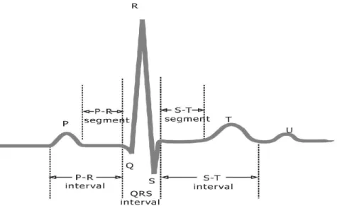
When the heart is beating, a special kind of movement is produced. This beat is able to create a voltage that can be measured in order to analyse derivations or anomalies of the body.
Figure 4. A heart pulse.(source:http://www.analog.com)
The P wave is the atrial depolarization. It comes from the superimposition of the
depolarization of the right atrium and left. The QRS complex is the electrical current according to the right and left ventricles. Q and S have negative values while R is the highest voltage. T is the repolarization of the ventricles.
The voltage of this movement is composed by a beating process inside the heart.[3] Depending of the length in seconds of some intervals or the voltage, it is possible to detect anomalies in the heart.
2.1.2 Temperature
The temperature measurement of the patient is important for the study. This is a good parameter to analyse the stress as was explained above in the background chapter.
It is possible to analyse if temperature is a normal value or if the patient has fever.
But the most important thing is to study the pattern of the temperature signal to stablish methods to analyse if stress is related with this.[4]
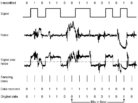
2.1.3 Noise
Transmissions that works by air have the main advantage of wires are not needed. The wire is a reliable transmission way because a fail does not affect to everything, only the section damaged so it is easier to replace and repair.
The wireless solutions have the comfortable advantage of wires installations are not needed. The problem is that the way followed by the data transmitted is full of problems. The main
problem in a wireless communication is the noise. This phenomenon can modify the signal and change the bits sent so if the noise is very high the original signal could not be recognised.
Figure 5. Example of noise.(source:http://www.technologyuk.net)
In order to fix this problem is difficult because some kind of noises does not depend of us. However is possible to use advanced techniques of transmission for minimize these troubles.
2.1.4 Interference
It is another phenomenon similar to the noise. In this case the problem occurs if in the area of the receiver exists machines or devices which are transmitting in the same frequency.
During the way of the communication the signal can be modified by external sources like wireless transmitters and the final signal could not be the same.
Figure 6. Types of interference.(source:http://physicaplus.org.il)
The constructive interference increases the amplitude of the wave while the destructive interference decreases the amplitude of the wave.
2.2 Hardware
First of all the signals measured are analogue. It will be important to treat these signals with a special hardware able to collect them.
The heart signal needs to be processed in order to get an unique signal from the sensors. A device to convert analogue signal to digital signal (ADC) is needed due to Bluetooth Protocol. Of course is needed a transmitter able to communicate with its equivalent. A receiver for data
2.3 Software
The digital signals converted will be data to treat in the other extreme. In order to get this goal will be necessary to program the device which sends the information in order to be able to be sent by the air.
On the other side the destination will need to be programmed as well. It has to be able to communicate with the receiver by some kind of medium. The software existent in the destination could receive a lot of packets and has to manage the process and receiving orderly.
A problem for this implementation could be the different tasks that have to be realized at the same time and the synchronization between applications to modify the shared resources or the timers.
3.METHOD
This chapter explains the way to solve the different problems described above.
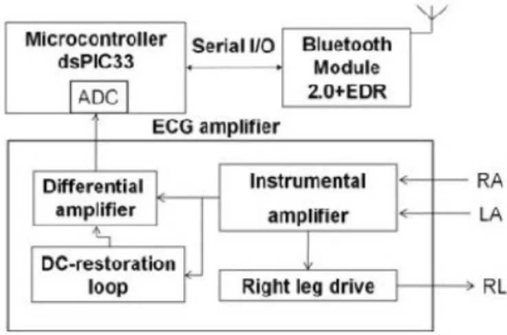
3.1 Sensor node
This device will be the most important part of the project because takes care of the data collection by temperature and ECG sensors. After takes measurements of the body it is necessary to organise them in order to send to the receiver.
Three ecg sensors are put on the right arm, left arm, and right leg. These three sensor are connected to the node to a suitable hardware which will treat this signal. One temperature sensor is connected to the node but to another input. A microcontroller works as an analogue-digital
converter taking the data which comes from the sensors and adapting them, in order to send to the Bluetooth Module. The Bluetooth module is the part which adapts the signal to the channel and transmits the bits to the receiver.[2]
Figure 7. Block diagram of ECG sensor node.[2]
3.2 Hardware model.
Now the method chosen has to be analysed to measure the parameters which are interesting for the process.
3.2.1 Electrocardiogram signals.
The sensors collect the three signals and are taken by the node through three inputs. These ones are inputs of an ecg amplifier.
Figure 8. ECG ampifier scheme.
The connecting electrodes (left arm and right arm) are connected to an instrumental amplifier. After this stage will be a differential amplifier and another kind of amplifiers made to create the unique ecg signal. The right leg drive reduces the common noise in the system.[2]
Figure 9. Phases of the heart pulse.(source:http://zone.ni.com)
3.2.2 Temperature signal.
In this project an analogue temperature sensor is used. The model is the TMP 35.It is a low voltage type sensor (2.7 V-5.5 V) and has accuracy centigrade measurements. The range of temperatures covered is -40ºC to 150ºC . The current which runs over the sensor is less than 50 uV. [6]
Figure 10. Graphics about Temperature Sensor.[6]
In this graphic is possible to see the relation between temperature and output voltage. The Figure 10 shows one of the configurations of the pins.
Figure 11. Place for the temperature sensor(red rectangle).
3.2.3 Communications without noise.
The noise is a parameter which can ruin the wireless communications. This problem is very
difficult to solve, sometimes only is possible to minimize the damage produced to the signal. There are a lot of types of noise and the best solution to keep it under control is considering the bandwith.
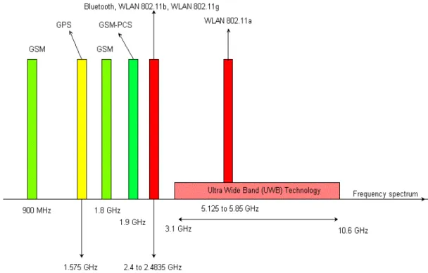
The bandwith is the spectrum where the communication is running. There is a relation between this spectrum and the rate which can be transmitted the information so a study about the relation should be done in order to get a good technique.
The white noise is extended for all frequencies so cannot be avoided it changing the frequency. Some noise is always modifying this signal.
Figure 12. Types of noise.(source:http://www.ldc.usb.ve)
The bandwith allows to transmit faster but the increase of the bandwith increase the amount of noise in the channel. Bluetooth transmit in the 2.4 Ghz band.
Figure 13 Spectrum of frequencies.(source:http://www.educypedia.be).
3.2.4 Communication between the receiver and the laptop.
The Bluetooth receiver has to be connected to the laptop in order to the program resident in the computer can collect the data received from the sensor node.
The hardware used is a cable RS-232 which is a serial port-usb converter. The serial port input is for the receiver and the usb input is for the laptop. This kind of interface is called universal asynchronous receiver-transmitter (UART) and has a protocol.
Figure 14. Scheme of the HCI UART.
The UART adds a new byte to the normal Host Controller Interface (HCI) packet. This byte is an HCI indicator and it marks the kind of packet received. Thus it is possible to know if is a
command, an event, an Asynchronous Connection-Less (ACL) data packet or a Synchronous Connection Oriented (SCO) packet.
Figure 15. HCI Packet Indicator.
3.3 Software model.
An application has been created in order to treat the parameteres (temperature and ecg signals) wich are received from the ecg module by air. This application is running in the laptop. The plattform used is Eclipse. The laptop is connected to a Bluetooth receiver (dongle) by serial port. This communication is important to implement well to avoid problems in the reception.
3.3.1 Bluetooth Protocol.
This protocol is used to transmit information wireless. This is a schematic of the protocol stack used. Figure 16. Bluetooth Stack protocols.
The protocols which are above the HCI borderline, are propietary protocols.
The Bluetooth Radio and the baseband allows a physical link vy radiofrecuency. They carry out tasks of modulation and demodulation.
The Baseband allows two types of physical links connection.
• ACL (Asynchronous ConnectionLess) .For data connections. Maximum of 721 kbps . • SCO (Synchronous connection oriented) for multimedia and real time voice 64kbps.
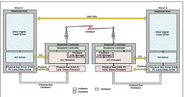
LMP (Link Manager Protocol) is the responsible of the configuration and control of the the negotiation of the packet size of the baseband packets. HCI is very important ( Host Controller Interface).It is the borderline between the protocol layers of the hardware and the software, supporting a command interface between the host device and the firmware of the controller
device . L2CAP allows the multiplex of different protocols over it because Baseband does not have a type field for the procotols.
Figure 17. Bluetooth overview.
First of all a communication has to be established. In order to get this, an ACL connection has to be completed, sending some commands to the controller to negotiate some parameters of the communications, identifiers of connection, addresses, work modes and speed.
Figure 18. Sequence Diagram ACL Connection.
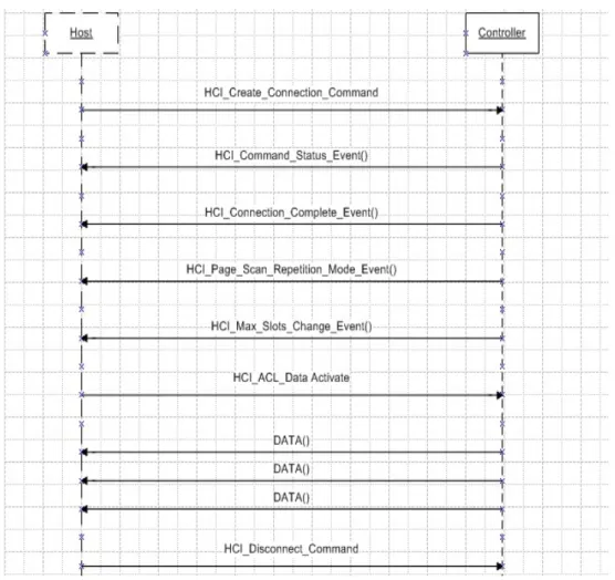
At the beginning the host sends a HCI_Create_Connection_Command in order to start the ACL connection sending as parameters the physical adress of the device to connect and another configuration parameters. If the controller sends back a Command_Status_Event is because the last request was sent to the another controller. It is possible to know if the request was sent succesfully if parameters as the status is 0 and the opCode is the same than the command. After this, if everything was ok, the controller sends to the host a HCI_Connection_Complete_Event as acknowledgment of the request, giving as parameters the Connection Handle (the identifier of the connection). The next two packets are packets to report of some changes finished succesfully about some parameters settings. When the ACL connection is done, just a first HCI_ACL_Data_Packet has to be sent in order to activate the data collecting. After that, data will being received until the ACL connection will be stopped with a Disconnect_Command.
3.3.1.1 Types of HCI packets.
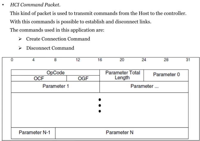
The packets are divided in three classes. • HCI Command Packet.
This kind of packet is used to transmit commands from the Host to the controller. With this commands is possible to establish and disconnect links.
The commands used in this application are: ➢ Create Connection Command ➢ Disconnect Command
Figure 19. HCI Command Packet.
OpCode: It is the code of operation of this command, each command has a different
code. It is divided in OpCode Command FieldOCF( 6 bits), one type of command of a group of commands, OpCode Group Field (OGF,4 bits).
Parameter total Length: Total length of all the parameters of the packet.
• HCI ACL Data Packets.
These packets can be considered the information, the digital signals transmitted by the sensor node but they have a header and a special structure to control the information. In order to start to receive Ecg and temperature data is essential to send a special command. In that moment the sensor node will start to collect data and transmit them to the receiver.
It has features like the first packet indicator or continuous packet.
Figure 20. HCI ACL Data Packet.
Connection Handle: It is the identifier for one ACL connection.
Packet boundary Flag (PB) : This indicate if the packet is the first fragment or is a continous fragment.
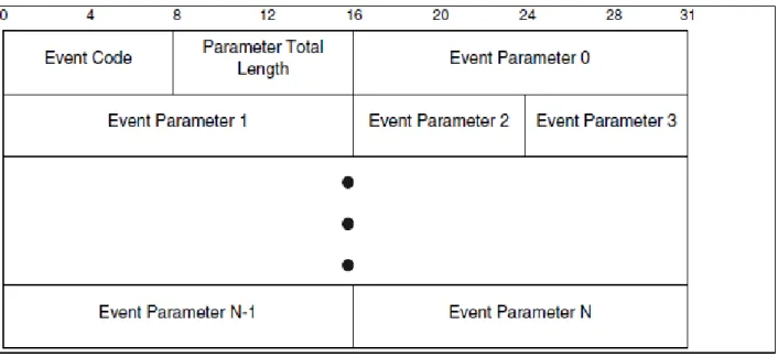
Broadcast Flag (BC) : It indicates if is a broadcast packet. Data Total Length: Length of the HCI_ACL_Data packet. • HCI Event Packets.
A response from the controller to the Host sometimes occurs. This situation happens when something changed in the communication and has to be noticed to the Host.
3.3.2 Temperature and ECG Data.
Data (ecg signals and temperature) is a part of the PDU (protocol data unit) of the HCI ACL Data Packets. The data part of the HCI ACL data packets has an internal protocol created to specify all types of data ( temperature, ecg).
Figure 22. Internal data protocol.
The first three fields are from the HCI ACL Data Packet and the logical link control and adaptation protocol (LCAP) ACL length is included in the Data of the PDU (Segment Data Unit, SDU). The LCAP ACL length consists of the total length of the packet ( they could be fragments and the total data does not have to be in the first packet) , data could be separate in more PDUs.
The Destination and From BD address are the addresses of the receiver(dongle) and the sensor node. They are media access control (MAC) addresses, physical identifiers to recognise every device. The packet type is the kind of data which is being collected (temperature or ECG). For starting the data collection the packet type is 0x09.
For the temperature there is an identifier (0x85) and for the ecg( 0x84) in hexadecimal notation. After the packet type, depending of the kind of the data, different parameters will be in those fields.
Parameters for ecg: 0x84 Ecg data
ECG packet nbr 2 bytes ( The number of the ECG packet) Timesstamp 4 bytes (Time when the collection was done) Data 1 LSB (8bits) 1 byte
Data 1 MSB (8bits) 1 byte …
Data (nbr of meas.) LSB 1 byte
Data (nbr of meas.) MSB 1byte
Parameters for temperature data:
0x85 Temperature packet
PacketNbr 2bytes, (unsigned integer) (Number of temperature packet)
TimeStamp 4 bytes, (two unsigned integer) (Time when the collection was done) Temperature data 2 byts, unsigned integer ( Temperature Data).
3.3.3 Data collection from RS-232 by events.
The data collection was a problem because an exhaustive research about Java and its Application Programming Interface (API) has been required.
The serial port cable has classes in Java to control this kind of device but is really difficult to use. First of all the java communications package has to be installed (javacomm). Besides if the applications is running over windows operative system a special file .dll will needed because this java package is not supported by windows. After this hard preparation the serial port has to be configured and open (COM1,COM2...). Some parameters have to be configured as speed or modes of transmission. A thread has to be created to listen the serial port if new data are available. It is possible to do that by an event listener associated to the serial port. Also an InputStream and OutputStream associated to the serial port to read and write in the port are needed.
When the port has been opened, the application has to continue its execution but the thread which was created is going to be listening the port until a event occurs.
The thread is not alerted about all events, just the events that have been configured. After data are received in the port, the thread starts to execute its code, and this code will takes care of read and process the bytes.
4.RESULTS
This chapter shows the results obtained in the tests and an analysis of them will be done.
4.1 Serial Port Installation in Windows 7
The laptop has not Bluetooth so a solution is needed. The Bluetooth receiver (dongle) has a serial port input and has to be connected to a computer with USB input. In order to fix this problem a Serial Port-USB adapter called RS-232 cable is used. The RS-232 cable needed a special software provided by the cable company so was not difficult to install it.
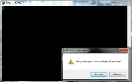
It was installed by the name of ”COM 1” and was possible to check out with the putty program if was well added.
Figure 24. Putty session with serial port.
This figure shows that the COM1 is opened well so is possible to work with it. In this case a laptop with Bluetooth integrated3
4.2 Java package installation.
In order to work with serial port in Java a new package is required, the java communications. From the sun website this package was installed as a .jar file. The first time when the program was
executed the result was the next Exception:
Error loading SolarisSerial: java.lang.UnsatisfiedLinkError: no SolarisSerialParallel in java.library.path
Caught java.lang.UnsatisfiedLinkError:
com.sun.comm.SolarisDriver.readRegistrySerial(Ljava/util/Vector;Ljava/lang/Strin g;)I while loading driver com.sun.comm.SolarisDriver
This problem exists because the library for Java provides this package is oriented to Linux and Solaris plattforms. The one chance to use this library in Windows is adding a special .dll file called ”win32com.dll” . This file allows working with the java library not oriented to Windows.[7] It could have been convenient Linux plattform because this problem does not exist. In order to fix this problem in Windows a research about serial port in windows was needed. Also was possible to work with external libraries created by particulars. There are some in internet but the java API was chosen to avoid implement with unknown packages. This solution also would have avoided to install the .dll file.
4.3 ACL connection
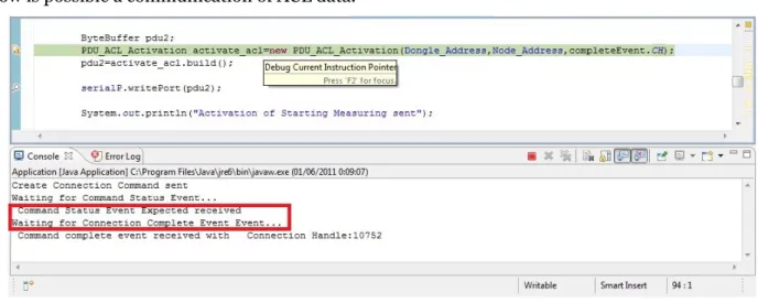
First of all to write on the outputStream a Create Connection Command is needed. In the diagram of ”Create an ACL connection”, this is the first command which has to be transmitted to the controller.
A command status event was received from the controller. Due to the status was '0' , that means that the operation was succesfull and the request was sent. Later a Connection Complete Event was received with status parameter '0' , so the ACL connection is established. This event contains the Connection Handle which is an identifier of the connection.
Figure 25. bytes of Connection Complete Event.
Now is possible a communication of ACL data.
Figure 26. Procedure of ACL Connection.
It could have been good if the most of the events are collected, because a lot of information is offered about the communication, the controller, the host, parameters of negotiation or speed, but in this case was enough with this job.
4.3.1 Start Data Collection Command.
A command to notice to the sensor node to start the data sending is needed. This PDU has the arquitecture of the HCI ACL Data packet. The packet type is 0x09 (ecg measurement) is dedicated to begin the collection of data (temperature and ecg) and has only one parameter, ON/OFF. To start the collection this parameter has to be '1'. If the flags (Packet Boundary Flag and Broadcast Flag) have no valid values or one of the MAC addresses is wrong, a Hardware Error will be received, with code '-2'.
After checking out the valid values of these parameters, an event called 'Number of Completed packet' was received with some parameters as the connection handle.
After this event, the data collection starts, and HCI ACL Data Packets start to be received continuosly until the communication is stopped.
Figure 27. Procedure of data collection.
The data are HCI ACL Data Packets with the internal protocol showed in the figure 22 . The field LCAP length is the total length of the ECG packet. This ECG Packet can be separated in several HCI ACL Data packets. The Data Total Length is the length of the HCI ACL Data Packet. It is possible to know if an ACL packet is the first one or is a continuos fragment due to the packet boundary flag (PB). The data bytes of the HCI ACL Data Packets are parameters which represents the ECG signal or the temperature value.
The data collection will be stopped when a minute is passed. This time is being controlled by a timeout. When this timeout is activated a flag of end collection(oneMinute) is on.
while(serialP.oneMinute==false){ now=System.currentTimeMillis(); serialP.resultTime=now-time;
if(serialP.resultTime==60000){ // A minute has passed serialP.oneMinute=true;
} }
System.out.println("A minute has passed."); }
It is really important check out if the communication is being succesfull because it could be a lot of errors. It is convenient to look some status parameters which tell us if everything is going okay.
Figure 28. Graphical ECG.
This is a graphic made with the data available from the measurements fo the procedure. The ordinate indicates the value in milivolts of the measurement while the abscissa indicates the number of measurement. If this graphic is compared with theorical signal, it is very equal.
740 ms
V(mv)
Each measurement has a sampling frequency of 500 Hz so this is 2 miliseconds. If the number of measurements are countedaproximately between two points repeated in the signal looking for the period, to calculate that is possible:
480-105 =375 measurements one signal complete.
375 measurements x 2 miliseconds =750 ms the total period. The frequency of this signal would be 1.33 Hz.
Figure 29. Graphical Temperature.
This could be an example of a graphic temperature during 24 hours. The values are in centigrades and the abscissa represents the time.
Now a scheme of the packets during the time and the period.
ECG 0
TEMP0
ECG 1 TEMP1 ECG 2
T0 : It is the time of the ECG clock, the time when the first measurement is done.
After this, each packet takes a different time. A complete ECG packet has a period of 200ms (2 ms each measurement). And the temperature packet takes 0.025 ms. The channel is being shared by two signals, ecg and temp. Each signal has its own Ts (Time Period) and frequency. Temperature needs less time to be transmitted.
If the connection gets down the system finishes to process all packets which are in the reception queue and saves them in the file. If the system restablishes the connection, starting a new process of requesting is not needed because the connection handle already exists and the system will start to collect the new data in a new file. The data missing are represented in the file by '0'. In the case which a connection is cut, the application recalculates the time left and complete the fields empties by `0`.
4.3.2 Saving to a file.
When the data are separated without headers of the HCI ACL Data packet, they have to be saved in a file. Files .bin have been used because this is the standard way to store bytes. Then will be easy to recover these information independent of the plattform. It is not very convenient to save the bytes in another type of file like a .txt file because the recover could be problematique.
These ones are the ECG data, the first two bytes are the packet number, and the 4 bytes next are the timestamp. The rest of the bytes are values of voltage in milivolts.
Figure 32. data bytes Temperature.
These ones are the temperature data, the figure above shows that the first two bytes are the packet number, and the 4 bytes next are the timestamp. The rest of the bytes are values of
temperature in centigrades.
4.4 Future Work.
The idea of the wireless sensor node is a good purpose to create ecg networks through wireless sensor networks. A database would be needed to store all the information and computers could manage the behaviour of the network. Graphics about the ECG and values of temperature will notify the state of the patient. And if something is wrong this pattern of the signal could be compared with another one in order to detect anomalies in the hart or illness.[5]
Even the sensors nodes could be work with another networks of sensors outside the range by a gateway.
This solution could open new researchs like sensors to help in the fires for the forests. Sensors communicated could transmit information about the area temperature and help to avoid fires.[8]
5. SUMMARY AND CONCLUSSIONS.
The ECG and temperature data according to some studies can be related with the stress. The sensor node collect every signal received from the single sensors and transmitt it by air with Bluetooth Protocol.
On the other side a receiver connected to the laptop by serial port collected the data from the sensor node. A program to control the flow of packets received was created in the laptop.
The program consists in two threads, one for the main execution and writting commands in the ouputStream and one thread listening the event of ”New Data Available” and then this thread read and proccess the bytes arrived to the queue of reception. Finally these bytes are saved into a file.
The system in general has worked well, but the dongle (bluetooth receiver) was not working very well so the tests were very hard.
The conclussion is that is a really good system to ecg for point-to-point connections and it could be extended to another areas or to create networks of ecg controlled by programs like this. The Bluetooth specification has been important to recognise the types of packets and a every significant field to fix some error situations. The important part was the point ”how to make an ACL connection” due to this chapter offered to us the theory and the packets which should be sent to start the communication. This is the windows solution, but in linux some things about the compatibility would have been easier. A laptop with Bluetooth integrated would have been more efficient and easier to implement. The dongle had failures very often and was difficult to try the application.
This is a good system to store and collect the data from the sensors but it does not represents signals or do any other job.
APPENDIX
This chapter shows important material as diagrams, source code...
Setting a serial Port in Java.
This is part of the code of the file SerialPortCOM.java and shows the configuration of a serial port through the java communications package.
The class SerialPort has to be configured by certain parameters. It is important to remind that exist two SerialPortCOM instances. One is created by the Application of the main Thread ( This one uses the method configurePort to prepare its working) and one else is created each time when available data event in serial port ocurrs. In order to get this purpose, a listener is activated and this kind of event.
public void serialEvent( SerialPortEvent _ev ) {
switch( _ev.getEventType() ) { case SerialPortEvent.BI: case SerialPortEvent.OE: case SerialPortEvent.FE: case SerialPortEvent.PE: case SerialPortEvent.CD: case SerialPortEvent.CTS: case SerialPortEvent.DSR: case SerialPortEvent.RI: case SerialPortEvent.OUTPUT_BUFFER_EMPTY: break;
// when we have available data this case is activated. case SerialPortEvent.DATA_AVAILABLE: this.readPort(); break; } }
The listener is always ready for the moment when available data is waiting from the serial port. In that moment the option notifyDataAvailable is activated and is the one event that the listener is going to treat. This treatment is to execute the case DATA_AVAILABLE, what means read bytes from the serial port. This thread will finish when available data in the queue ends. These variables has to be static because if the thread runs out, the configuration has to remain.
static Enumeration portList;
This variable has the list of ports available in the system.
static CommPortIdentifier idPort;
This variable has a specific port.
static SerialPort serialPort;
This is the class which takes care of the serial port configuration.
static OutputStream output;
This is the output, where we will write the data to send to the sensor node.
static InputStream input;
This is the input, where we will read the data from the sensor node. Input and output are associated to the SerialPort.
/**
* This method configure the features of the port and gets an input and output. */
public void configurePort()
{
portList = CommPortIdentifier.getPortIdentifiers();
while( portList.hasMoreElements() ) {
idPort = (CommPortIdentifier)portList.nextElement();
if( idPort.getPortType() ==CommPortIdentifier.PORT_SERIAL) { if( idPort.getName().equals("COM1") )
{ // If port is not in use, we try to open it.
try {
serialPort=(SerialPort)idPort.open("Application",2000);
} catch( PortInUseException e ) {} // We get an output channel.
try {
output = serialPort.getOutputStream(); input = serialPort.getInputStream();
}catch( IOException e ) {
System.out.println("Unexpected serial port error. "); }
// We add an event listener for listen the port try {
serialPort.addEventListener( this ); } catch( TooManyListenersException e ) {}
// We activate the notifications of data in serial Port.
serialPort.notifyOnDataAvailable( true );
SerialPort.PARITY_NONE ); } catch( UnsupportedCommOperationException e ) {} } } } }
PDU format in java.
For the packets sent, an special arquitecture in Java has been chosen. It had to be an array of bytes, a buffer. First of all a bytes array has to be declared with the specific number of bytes.
byte[] pdu=new byte[21];
Later a buffer for bytes will be used, and assign the last bytes array will be needed.
ByteBuffer buffer = ByteBuffer.wrap(pdu);
So it is possible to use methods to write and read the byte buffer in order to create PDUs.
buffer.put(HCI_packet_indicator);
ECG and Temperature Files Stored in Java.
The data has to be saved in files which can be recovered later easily. The extension chosen has been .bin because is a standard extension for every plattforms. It is the format binary therefore it is perfect to store bytes.
The example exposed from the code of the application: Class ACLHandler:
public void processAclData()throws DataException{ for(int i=0; i<ecg.size();i++){
try {
ecg_output.write(ecg.get(i)); } catch (IOException e) {
// TODO Auto-generated catch block
throw new DataException(e.getMessage()); }
}
// If the time is not finished and we have to put 0 in the file.
long timeNow=System.currentTimeMillis(); long remainTime=0; while(remainTime<SerialPortCOM.finalTime) { try { ecg_output.write(0); } catch (IOException e) {
// TODO Auto-generated catch block
throw new DataException(e.getMessage()); }
timeAfter=System.currentTimeMillis(); remainTime=timeAfter-timeNow;
} }
System.out.println("ECG DATA SAVED SUCCESFULLY IN ecg.bin"); for(int j=0; j<temperature.size();j++){
try {
temp_output.write(temperature.get(j)); } catch (IOException e) {
// TODO Auto-generated catch block
throw new DataException(e.getMessage()); }
}
//if one minute is not passed and we have to store '0' in the temperature file. if(SerialPortCOM.complete==true){ long timeAfter; long timeNow=System.currentTimeMillis(); long remainTime=0; while(remainTime<SerialPortCOM.finalTime) { try { temp_output.write(0); } catch (IOException e) {
// TODO Auto-generated catch block
throw new DataException(e.getMessage()); } timeAfter=System.currentTimeMillis(); remainTime=timeAfter-timeNow; } } try {
try {
temp_output.close(); } catch (IOException e) {
// TODO Auto-generated catch block
throw new DataException(e.getMessage()); }
System.out.println("TEMPERATURE DATA SAVED SUCCESFULLY IN temp.bin");
}
Class Diagram.
Default Package:Figure A1. Class Diagram.
• TotalLengthPDUS
This class contains the length of the events treated in this application in order to know the real length of the events packets. It is used for the SerialPortCOM.
• ACLHandler
This is the class which takes care of the data treated from the SerialPortCOM. It collects the lists of bytes (temperature and ecg) and stores the information in two separated files.
It has the main method which starts the execution of the main thread. It calls to the ConnectionManager.
• ConnectionManager
It takes care of the ACL connection, managing and collecting the events related with it and doing possible the communication. It calls the reading and writing methods from SerialPortCOM. • EventHandler
This class collects the essential information of every event packet coming in order to know important parameters for the communication.
• SerialPortCOM
Activity Diagram
It shows the behaviour of the application. There are two threads. One is the main thread and could be considered the main application which starts the procedures. The another thread is a listener which wakes up when new data is in the serial port. This thread treats the packet and process them. Main Thread
Figure A2. Main Thread Activity Diagram.
This activity diagram shows the process of the main Thread since is awake. The main
Thread configures the Port, setting the parameters of the serial interface RS-232. Although the Port Exception is not showed in the diagram, this exception could be throw by the method
Configure Port
ActivateThreadRX
Send PDU Create Connection
Activate Timer
CommandStatusEventException
TimeOutException
TimeOutException Send Start Data Collection
Wait 1 minute
EndAclConnection
DataException Command Status Event
Timer Finished? Connection Complete Timer finished? Result Yes No Yes No No
The Expected One? Yes
Yes No Yes No No Yes
of the applications, suddenly they can be throw if internal problems are detected. After activating the listener Thread, a Create Connection Command is sent (written in outputStream) to be
delivered to the Bluetooth Receiver(Dongle) and later to the ECG sensor node. A timer is activated for stopping the wait if the command status event is not received. (TimeOutException).
Even if a Command Status Event is received, it is important to check if this command is the expected one, because must to have status '0'. If everything was ok and a Connection Complete Event is received the ACL connection is established. Then an ACL data Packet has to be sent. This packet has a parameter which order the data collecting of ECG and temperature. Since this moment Data packets are being received, and will be collected them for 1 minute. After that countdown, a Disconnect Command will be sent, and the thread will finish.
Thread Receiver
Figure A3. Receiver Thread Activity Diagram.
Since the moment when this Thread receives a new data available event, it starts to read the port storing the bytes in a buffer. Each time one byte of this buffer will be read, sorting if is an event packet or ACL data packet. It will process the bytes detecting the events and saving the temperature and ecg data in buffers which will be saved later.
Events not related and important for ACL connection are ignored. Read Port
Read Byte Queue Bytes Left?
Read 1 Byte
Process Event for Connection ACL?
End of Packet?
Call Event Handler
Process
Save Data
Un minute passed and Process Finished? Yes Yes Yes Yes Yes No No No No No
Source Code
import Exceptions.CommandStatusEventException; import Exceptions.DataException; import Exceptions.PortException; import Exceptions.TimeoutException; /*** Main class. It starts the procedures needed for the data reception. * @author Francisco Cánovas Camino
* */
public class Application { /**
* Main method. * @param args */
public static void main(String[] args) {
SerialPortCOM comPort=new SerialPortCOM(); // Serial Port Communication.
// ECG Node Bluetooth Address byte [] node_address=new byte[6]; node_address[0]=0x35; node_address[1]=(byte)0xf3; node_address[2]=0x28; node_address[3]=(byte)0x96; node_address[4]=(byte)0xa0; node_address[5]=0x00;
// Dongle Bluetooth Address
byte [] dongle_address=new byte[6]; dongle_address[0]=0x00; dongle_address[1]=(byte)0x80; dongle_address[2]=0x37; dongle_address[3]=(byte)0x29; dongle_address[4]=(byte)0x3d; dongle_address[5]=(byte)0x2a; try { comPort.configurePort(); } catch (PortException e) {
start(manager); // Starting procedures of reception. }
/**
* It is the method for starting the procedures of reception.
* @param manager It takes care of the connections with the Serial Port.
*/
public static void start(ConnectionManager manager){ try {
manager.CreateACLconnection();
} catch (CommandStatusEventException e) { System.out.println(e.getMessage()); } catch (TimeoutException e) {
// TODO Auto-generated catch block System.out.println(e.getMessage()); } catch (DataException e) {
// TODO Auto-generated catch block System.out.println(e.getMessage()); } catch (PortException e) {
// TODO Auto-generated catch block System.out.println(e.getMessage()); }
} }
import Exceptions.CommandStatusEventException; import Exceptions.DataException; import Exceptions.PortException; import Exceptions.TimeoutException; import commands.*; import events.Command_Status_Event; import events.Connection_Complete_Event; import java.nio.ByteBuffer; /**
* This class take care of set up the ACL Connections. * @author Francisco Cánovas Camino
*/
public class ConnectionManager { private byte[] Node_Address; private byte[] Dongle_Address; private SerialPortCOM serialP; private EventHandler eventHandler; private boolean timeout;
/** This constructor takes the addreses and the serial port created.
* @param node_address Address from the ecg node.
* @param dongle_address Address from the dongle connected to the computer.
* @param port Serial Port initialized. */
public ConnectionManager(byte[] node_address,byte[] dongle_address,SerialPortCOM port){ Node_Address=node_address; Dongle_Address=dongle_address; eventHandler=new EventHandler(); serialP=port; serialP.oneMinute=false; serialP.resultTime=0; serialP.finalTime=0; serialP.resultCollect=false; serialP.collectingACL=false; serialP.complete=false; timeout=false; } /**
* Constructor of connection manager. */
* @throws DataException * @throws PortException */
public void CreateACLconnection() throws
CommandStatusEventException, TimeoutException, DataException, PortException{
Command_Status_Event statusEvent=new Command_Status_Event(); Connection_Complete_Event completeEvent=new
Connection_Complete_Event();
PDU_Create_Connection create_pdu=new PDU_Create_Connection(Node_Address);
ByteBuffer pdu;
pdu=create_pdu.build(); // I create the pdu Create_Connection
serialP.writePort(pdu); //Now I send the pdu to the serial Port to write.
System.out.println("Create Connection Command sent"); System.out.println("Waiting for Command Status Event..."); long time; time=System.currentTimeMillis(); long now; long result; while(eventHandler.command_status_event==false) { now=System.currentTimeMillis(); result=now-time;
if(result==10000){ // A minute has passed this.timeout=true;
throw new TimeoutException("No Command Status Event response from the dongle. Timeout Excedeed");
} }
this.timeout=false;
// I have received a command status event because the while finished.
if((statusEvent.status==0x00)&&(statusEvent.ocf==create_pdu.getOCF())) { // It is the command status event expected.
System.out.println(" Command Status Event Expected received");
} else
{ //It is not a command status event expected if(statusEvent.status==0x0b){
}
else{ // Command not expected
throw new CommandStatusEventException("Command Status Event not expected:"+ "Status ->" +
statusEvent.status + "\tOperation Code:" + statusEvent.getOpCode());
} }
if(statusEvent.status!=0x0b){
System.out.println("Waiting for Connection Complete Event Event..."); long time2; time2=System.currentTimeMillis(); long now2; long result2; while(eventHandler.connection_complete_event==false) { now2=System.currentTimeMillis(); result2=now2-time2;
if(result2==10000){ // A minute has passed this.timeout=true;
throw new TimeoutException("No Command Status Event response from the dongle. Timeout Excedeed");
}
}
if(completeEvent.status==0){ // ACL connection created successfull
System.out.println(" Command complete event received with\t" +
"Connection Handle:"+ completeEvent.CH); }
}
// Send Activation of ECG and Temperature reception. ByteBuffer pdu2;
PDU_ACL_Activation activate_acl=new
PDU_ACL_Activation(Dongle_Address,Node_Address,completeEvent.CH); pdu2=activate_acl.build();
timer(); // Activation of the timer during 1 minute. if(serialP.resultCollect==false){
throw new DataException("Data no received from the Ecg Module, but signal of start sent");
}
//Send PDU Stop Measuring
ByteBuffer pdu3;
PDU_ACL_Disconnect disc=new
PDU_ACL_Disconnect(Dongle_Address,Node_Address,completeEvent.CH); pdu3=disc.build();
serialP.writePort(pdu3);
System.out.println("PDU Stop Measuring sent"); //llamar a ENDACLconnection
this.EndACLconnection(completeEvent); }
/**
* This method takes care of count 1 minute and notice somewhere. */
public void timer(){
long time=System.currentTimeMillis(); long now;
System.out.println("The countdown of 1 minute has started...");
while(serialP.oneMinute==false){ now=System.currentTimeMillis(); serialP.resultTime=now-time;
if(serialP.resultTime==60000){ // A minute has passed serialP.oneMinute=true;
} }
System.out.println("A minute has passed."); }
/** This class finish the ACL connection.
* @param completeEvent It has information needed for end the connection.
* @throws PortException */
public void EndACLconnection(Connection_Complete_Event completeEvent) throws PortException{
ByteBuffer pdu4; byte reason=0; PDU_Disconnect disco=new PDU_Disconnect(completeEvent.CH,reason); pdu4=disco.build(); serialP.writePort(pdu4);
System.out.println("PDU ACL Connection Disconnect sent.");
} } import java.io.*; import java.nio.ByteBuffer; import java.util.*; import javax.comm.*; import Exceptions.DataException; import Exceptions.PortException; /**
* This class manage and take care of the connections with the serial port.
* @author Francisco Cánovas Camino */
public class SerialPortCOM implements SerialPortEventListener { static Enumeration portList;
static CommPortIdentifier idPort; static SerialPort serialPort; static OutputStream output; static InputStream input;
private byte[] length_data_acl; private byte[] length_lcap_acl;
private ByteBuffer length_data_acl_buffer; private ByteBuffer length_lcap_acl_buffer; private List<Byte> packetACL; //
private List<Byte> packetTemperature; // private int index;
private int tPacket; private int length;
private int lengthParametersTotal; private int lengthParametersTemp; private boolean end_packet;
private ByteBuffer r_packet; private byte[] packet;
private byte[] rpacket;
private EventHandler eventHandler; private TotalLengthPDUS lengther;
static long resultTime;
private boolean firstPacket; private int counter;
private boolean ACLend; private int tipoPacket; private boolean valid_packet; private int iECG;
private int iTEMP; static long finalTime;
static boolean resultCollect; static boolean collectingACL; static boolean complete;
/** * Constructor. */ public SerialPortCOM(){ length=0; index=0; tPacket=0; lengthParametersTemp=0; lengthParametersTotal=0; end_packet=false;
lengther= new TotalLengthPDUS(); packetACL=new ArrayList<Byte>(); packetTemperature=new ArrayList<Byte>(); iECG=1; iTEMP=1; } /**
* This method configure the features of the port and gets an input and output.
* @throws PortException */
public void configurePort() throws PortException { portList = CommPortIdentifier.getPortIdentifiers(); while( portList.hasMoreElements() ) { idPort = (CommPortIdentifier)portList.nextElement(); if( idPort.getPortType() == CommPortIdentifier.PORT_SERIAL ) { if( idPort.getName().equals("COM1") )
// If port is not in use, we try to open it. try { serialPort = ( SerialPort ) idPort.open("Application",2000); } catch( PortInUseException e ) {
throw new PortException(e.getMessage()); }
// We get an output channel. try { output = serialPort.getOutputStream(); input = serialPort.getInputStream(); } catch( IOException e ) {
throw new PortException(e.getMessage()); }
// We add an event listener for listen the port
try {
serialPort.addEventListener( this ); } catch( TooManyListenersException e ) { throw new PortException(e.getMessage()); }
// We activate the notifications of data in serial Port.
serialPort.notifyOnDataAvailable( true );
// Fixing the parameters of the port. try { serialPort.setSerialPortParams( 115200, SerialPort.DATABITS_8, SerialPort.STOPBITS_1, SerialPort.PARITY_NONE ); } catch( UnsupportedCommOperationException e ) {
throw new PortException(e.getMessage()); }
} }
}
case SerialPortEvent.BI: case SerialPortEvent.OE: case SerialPortEvent.FE: case SerialPortEvent.PE: case SerialPortEvent.CD: case SerialPortEvent.CTS: case SerialPortEvent.DSR: case SerialPortEvent.RI: case SerialPortEvent.OUTPUT_BUFFER_EMPTY: break;
// when we have available data this case is activated. case SerialPortEvent.DATA_AVAILABLE: try { this.readPort(); } catch (PortException e) {
// TODO Auto-generated catch block System.out.println(e.getMessage()); } catch (DataException e) {
// TODO Auto-generated catch block System.out.println(e.getMessage()); } break; } } /**
* This method write bytes in the serial port. * @param pdu
* @throws PortException */
public void writePort(ByteBuffer pdu) throws PortException{ try
{
byte[] pduReal= pdu.array(); output.write(pduReal);
} catch( IOException e ) {
throw new PortException(e.getMessage()); }
} /**
* This method process each byte we receive from the serial port. * @param field
* @return */
// Cheking the first byte. HCI indicator. if(index==0){
if(field==0x04){ //event tPacket=0x04;
}
if (field==0x02){ // acl packet tPacket=0x02; ACLend=false; } } else { if(tPacket==0x04){ // event if(index==1){ if(field==0x0f || field==0x03){//type of event.
rpacket= new byte[lengther.getLength(field)]; //length expected r_packet=ByteBuffer.wrap(rpacket); valid_packet=true; } else { valid_packet=false; } }
if(index==2){ // length of the parameters lengthParametersTotal=field; lengthParametersTemp=lengthParametersTotal; } if((index>=0&&index<=2 )) // non-bytes of parameters { if(valid_packet){ r_packet.put(field); } }
if(valid_packet){ r_packet.put(field); //saving } lengthParametersTemp--; if(lengthParametersTemp==0){ end_packet=true; } }
if(end_packet) // end of the packet {
index=-1;
end_packet=false; if(valid_packet){
eventHandler=new EventHandler(); //sending to the handler
eventHandler.eventSorter(r_packet); } } } } if(tPacket==0x02){ //acl
if(index==2){ //connection handle and flags. if(field==32){ // first packet
ACLend=false; firstPacket=true; }
if(field==16){ // continuing packet firstPacket=false;
} }
if((firstPacket==true)&&index==3) // first byte of data total length
{
length_data_acl=new byte[2];
length_data_acl_buffer=ByteBuffer.wrap(length_data_acl); length_data_acl_buffer.put(1, field); }
if((firstPacket==true)&&index==4){ // second byte of data total length
counter=0; }
if((firstPacket==true)&&index==5){ //lcap length length_lcap_acl=new byte[2]; length_lcap_acl_buffer=ByteBuffer.wrap(length_lcap_acl); length_lcap_acl_buffer.put(1,field); } if((firstPacket==false)&&index>=5){ //data if(lcap_total_length>counter+15){ packetACL.add(field); counter++; } if(lcap_total_length==counter+15){ // end of the packet?? index=-1; counter=0; lcap_total_length=0; data_total_length=0; ACLend=true; } }
if((firstPacket==true)&&index==6){ // second byte of data total length
length_lcap_acl_buffer.put(0,field); lcap_total_length=length_lcap_acl_buffer.getShort(0);
}
if((firstPacket==true)&&index==19){ // packet type
if(field==-123){ // temperature System.out.println("Temperature Packet"+ iTEMP); tipoPacket=2; iTEMP++; } if(field==-124){ // ecg
System.out.println("ECG Packet"+ iECG); iECG++;
if((firstPacket==true)&&index>19){ if(tipoPacket==1){ //ecg
packetACL.add(field); // stored in the list counter++; } if((tipoPacket==2)&&(index<=27)){ //temp packetTemperature.add(field); counter++; } if(data_total_length-15==counter){ // end of the packet? index=-1; } if(lcap_total_length==counter+15){ //end of the complete packet?
index=-1; counter=0; lcap_total_length=0; data_total_length=0; ACLend=true; } } } } return(0); } /**
* This method read from the input of the serial port. * @throws PortException
* @throws DataException */
public void readPort() throws PortException, DataException{ int i; int result; try { length=input.available(); while((length>0)&&(breaker==0)) {
if(length<=4000) { packet=new byte[length]; result=input.read(packet,0,length); } else { packet=new byte[4000]; result=input.read(packet,0,4000); }
if(result!=-1){ // there is data
for(i=0;(i<length)&&(breaker==0);i++){ processBytes(packet[i]);
if((oneMinute==true)&&(ACLend==true)) { // 1 minute passed?everything is saved?
breaker=1; } index++; } if(breaker==1){ index=0; } } length=input.available();
//if the there are no bytes anymore and we are collecting ACL and packet could not be proccesed.
if((this.collectingACL==true)&&(length==0)) { ACLend=true; calculateRemainTime(); oneMinute=true; complete=true; } } if((ACLend==true)&&oneMinute){ ACLhandler aclH=new ACLhandler(packetACL,packetTemperature);
aclH.processAclData(); //processing acl data. SerialPortCOM.collectingACL=false;
input.close(); serialPort.close(); }
}
catch(IOException io){
throw new PortException(io.getMessage()); }
breaker=0; }
/**
* This method calculates the time left when the connection has been lost.
* */
public void calculateRemainTime(){
finalTime=60000-resultTime; //Time to complete with 0. } } import java.nio.ByteBuffer; import events.Command_Status_Event; import events.Connection_Complete_Event; /**
* This class handle the events received. * @author Francisco Cánovas Camino
* */
public class EventHandler {
static boolean command_status_event=false; static boolean connection_complete_event=false;
/** * Constructor */ public EventHandler(){ } /**
* This methods classify the events. * @param eventPacket
*/
public void eventSorter(ByteBuffer eventPacket){ //check the first byte, the event code. byte eventCode=eventPacket.get(0); switch(eventCode){
case 0x0f: //command status event {
commandStatusEvent(eventPacket); }
break;
case 0x03: //connection complete event { connectionCompleteEvent(eventPacket); } break; } } /**
* This method gets information of the command status event. * @param eventPacket
*/
public void commandStatusEvent(ByteBuffer eventPacket){ byte status=eventPacket.get(2);
byte num_HCI_commands=eventPacket.get(3); byte ocf=eventPacket.get(4);
Command_Status_Event ces=new
* This method gets information of the Connection_Complete event. * @param eventPacket
*/
public void connectionCompleteEvent(ByteBuffer eventPacket){ byte length_params=eventPacket.get(1); byte status=eventPacket.get(2); short connection_handle=eventPacket.getShort(3); Connection_Complete_Event cce=new Connection_Complete_Event(status,connection_handle); connection_complete_event=true; } } /**
* This class give the total length of some PDUS. * @author Francisco Cánovas Camino
* */
public class TotalLengthPDUS {
public final int length_command_status_event=6;
public final int length_connection_complete_event=13; /**
* This method gets the length of the event required. * @param eventCode
* @return */
public int getLength(byte eventCode){ int totalBytes=0; switch(eventCode){ case (0x0f) : { // command_status_event totalBytes=length_command_status_event; } break;
case (0x03) : { //connection complete event
totalBytes=length_connection_complete_event; }
break; }
} } import java.io.*; import java.util.List; import Exceptions.DataException; /**
* This class handle the ACL data. * @author Francisco Cánovas Camino *
*/
public class ACLhandler { private List<Byte> ecg;
private List<Byte> temperature; private FileOutputStream ecg_output; private FileOutputStream temp_output; private File ecg_file;
private File temp_file; /** * Constructor. * @param packetEcg * @param packetTemperature * @throws PortException */
public ACLhandler(List<Byte> packetEcg,List<Byte> packetTemperature) throws DataException{
ecg=packetEcg; temperature=packetTemperature; ecg_file=new File("ecg.bin"); temp_file=new File("temp.bin"); try { ecg_output=new FileOutputStream(ecg_file); temp_output=new FileOutputStream(temp_file); } catch (FileNotFoundException e) {
// TODO Auto-generated catch block
throw new DataException(e.getMessage()); }
} /**
* This method proccess data and store in a file. */