https://doi.org/10.47260/jesge/1123 Scientific Press International Limited
Irrigation projects in Iraq
Mukhalad Abdullah1 and Nadhir Al-Ansari2Abstract
Iraq has a unique irrigation system since the early history, these systems are functioning through many irrigation projects built over `Tigris and Euphrates Rivers. Irrigation projects include several categories, which are dams, barrages, canals, drains, pumping stations, regulators, and reservoirs.
There are six large dams inside Iraq, 5 are existing in Tigris basin, and one in Euphrates basin, these dams which were built since 1950’s are suffering from several issues, like foundation liquefaction, seismic effects, and others.
Tharthar Lake, Habbaniyah Lake, Razzaza Lake, and Southern Marshes are also one of the main projects in Iraq to control flood and storing excess water in some. These lakes serve in protection of the main cities during large floods.
There are also many barrages on Tigris and Euphrates, some of these barrages are part of Tharthar and Habbaniyah projects, while others serving the irrigation projects in Mesopotamia.
On Euphrates, there are several irrigation projects, where the projects upstream Fallujah city are almost small or medium projects irrigated by pumping. Then, in the rest of Euphrates, there are Great Abu Ghraib project, Great Mussayab, Hilla-Kifil, some small projects, and Kifil-Shinafiyah projects. Also, Hilla branch which is the largest branch in Iraq from Euphrates, where this branch is irrigating several irrigation projects.
On Tigris basin, there are Jazeera project irrigated by pumping from Mosul Dam, Kirkuk project that is irrigated from Lesser Zab River, and Diyala are projects. Inside Mesopotamia and over Tigris reach, there are Ishaqi project, Nahrawan project, Middle Tigris projects, Dujailah project, Dalmaj project, and Gharraf Canal projects.
In the middle of Mesopotamian plain, Main Outfall Drain was completed in 1992, this grand drain are serving around 6 million donum of farmlands.
Keywords: Dams, Barrages, Irrigation canals, Iraq.
1 Consultant engineer, Baghdad, Iraq.
2 Lulea University of Technology, Lulea, Sweden.
Article Info: Received: October 27, 2020. Revised: November 1, 2020. Published online: November 15, 2020.
1. Introduction
Since the early history, Iraq was known with irrigated agriculture, which was the trigger of civilization. The projects to regulate, store, and distribute water quantities in Tigris and Euphrates Rivers are existing centuries ago. After the establishment of new Iraq in 1921, the wheel moved again to build irrigation mega project, which extends along Iraq from north to south and from east to west.
In this report information was compiled to manifest the water resources projects which include dams, barrages, regulators, pumping stations, canals, drains, reservoirs, and many others.
First, dams and barrages will be demonstrated, then reviewing the irrigation main schemes on Tigris main course, Tigris Tributaries, and Euphrates main course. At the end, a review presented about Main outfall drain and other main drains in Mesopotamia.
2. Large Dams
Development Board was first interested in the large dams, Doukan and Darbendhikhan Dams were first constructed during Development Board era. Later, at the second half of 1970s, the interest was coming to front again, where the second batch of dam had built, Hemrin, Haditha, and Mosul Dams. In the 1990s, Adhaim Dam was built. There are still in the agenda, the construction of Bekhme and Makhoul Dams.
2.1 Mosul Dam
Studies were initiated to for the dam by Development Board through the companies (Alexander Gibbs & Partners) and (Munsel Basford and Bafrey), they prepared a study and submitted a joint report in 1953 that included the proposal of two sites near the moonlight village north of Aski Mosul, the proposals included a storage dam with a capacity of 8.7 billion cubic meters, and elevation of 320 m a.s.l. Then, the American company Harza was commissioned by Development Board to study the project and it presented the full report in 1960, Harza Company has indicated that the proposed previous sites are not appropriate geologically and proposed two new locations; the first has a capacity of 7.8 billion cubic meters at elevation of 320 m a.s.l. and the second has a capacity of 13.5 billion cubic meters and elevation of 325 m a.s.l.
Soviet Company Technopromexport submitted a new study in 1962 and a proposal for a new storage dam with a capacity of 7.7 billion cubic meters at elevation 312 m a.s.l. Then, Imatran Voima Company was assigned to prepare a study for the proposed dam and it was presented in 1973, the report has been evaluated by Technopromexport and Board of Experts, they both raised notes concerning the dam and the need to intensify geological investigations. Next, the dam construction proposal presented for Hochtief Company to do it in 1974, and after the company review, the agreement did not happen due to the foundations issue of the dam. The
French company, Solseif, was later commissioned to conduct geological investigations and presented its findings in 1979. Finally, agreement was reached with the Swiss consultants to prepare the dam study, which was presented in 1979 (Adamo, Al-Ansari, et al. 2018; Al-Simawi, 2008).
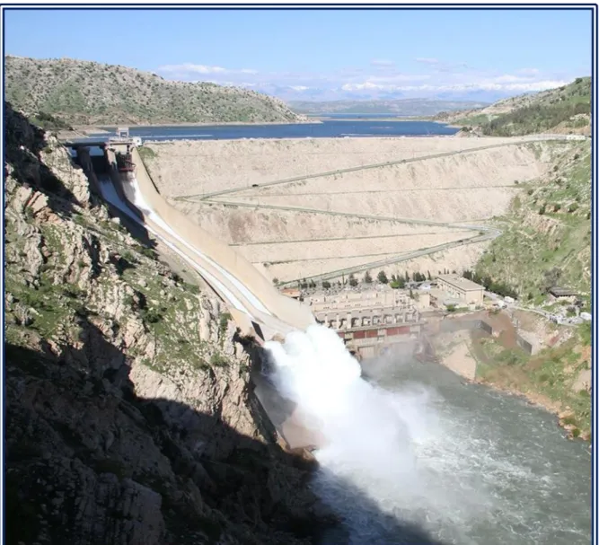
What has been manifested about studies, where many parties had been involved with an approaching results highlights clearly the sensitivity of Mosul Dam foundations, which resulted that the consulting companies and decision makers to re-examine and study the dam site several times, they convened a final conclusion that the dam underneath has gypsum formations which made a threat to the safety of the dam proposal, the alternative between the site and another of what it takes less remedies, and it will not be possible to find a site far of this negative findings. The length of the dam is 3,600 m, it is and earth fill dam with a clay core. The tallest height of the dam is 100 m and the operational level is 330 m a.s.l. The design storage is 11.11 billion cubic meters. The minimum operational level is 300 m a.s.l., below a dead storage equals to 2.95 billion cubic meters, as the live storage is 8.16 billion cubic meters. The dam has a gated spillway on the left side; the spillway maximum discharge is 7400 m3/s at the maximum flooding level of 338.5 m a.sl. The length of the spillway is 1.013 meters and the width is 50 meters. The flow energy through Flip-bucket end of the spillway which directed the flow 25o of horizon, Figure 1 Shows a general view of Mosul Dam (Adamo, Al-Ansari et al. 2018; Al-Simawi, 2008; USACE, 2003).
The dam includes 4 power units of Francis turbines on the right side of the dam with a total capacity of 750 MW. On the right side also, there are 2 bottom outlets that ensure a minimum discharge of 330 m3/s at the elevation of 300 m a.sl. The dam also includes two diversion tunnels on the right side of the dam shoulder. The project includes a pumped storage hydropower station by storage and pumping, this station aims to meet the consumption during the peak of energy demand without wasting quantities of water. The water is stored in an artificial lake with a capacity of 11 million cubic meters constructed above Taira Hill to the right of the dam, where this plant generates 200 megawatts. There is also within the body of the dam the outlet of the South Jazeera irrigation project, which has not been completed yet, and there is a proposed hydropower station in the outlet route (Adamo, Al-Ansari, et al. 2018; Al-Simawi 2008; USACE 2003).
Figure 1: General view of Mosul Dam (Edited by Author). (“Trevi Group Website” n.d.).
Mosul Dam includes as fuse-plug dam on the left side of the main dam, grouting tunnels, electric transformers, piezometers, as well as infrastructure for control, management, grouting and other services. Beneath the main dam, the grouting blanket had been implemented with 20 lines and depths of (25-10m). Further; the curtain grouting were implemented which consists 5 lines, three of them are vertical, and the two on both sides has inclination of 6o, the curtain grouting varies in depth and reaching up to 150 m.(Kelley et al. 2007).
Downstream of the main dam and at a distance of 9 km, the regulation dam was built on Tigris stream to control the high discharges from power plants and ensure a minimum discharge 330 m3/s. This dam was implemented by Austrian company Allen Union. The length of the regulation dam is 381 m and the height is 20 m; it is an earth fill dam with storage capacity of 21 million cubic meters. The dam includes tunnels, bottom outlets, spillway and power station that have 4 units of Kaplan turbines with a capacity of 60 MW.(Adamo, Al-Ansari, et al. 2018; Al-Simawi, 2008; USACE, 2003). Refer to Figure 2, The Regulation Dam, Mosul Dam project.
Figure 2: General view of the Regulation Dam, Mosul Dam project (MoWR n.d.).
After the opening of Mosul Dam in 1986, the leaks began to appear from the downstream of the dam body at rates higher than the expected rates. Measurement data for sensors in the dam were periodically discussed with Board of Experts. As a result, they decided that the dam administration to continue the grouting during the service life of the dam. Several sinkholes appeared in the dam site, the first sinkhole occurred in 1986, this was followed by a group of sinkholes that occurred from 1992 to 1998, these sinkholes lying nearly on an axis that parallel to main dam axis. There was also a spring observed in the river stream near the right bank. In February 2003, a large sinkhole occurred suddenly in the left bank near the curtain and the main dam. Also, another one occurred in 2005. A further sinkholes and cavities discovered at the bed of the lake itself and in the surrounding areas. As a result, Board of Experts had recommend to limit the storage at elevation of 319 m a.s.l. (Adamo, Al-Ansari, et al. 2018; Kelley et al. 2007; (Sissakian et al., 2018; Adamo, Sissakian, Al-Ansari, Knutsson, et al. 2018). Figure 3 shows the locations of sinkholes on the right bank downstream Mosul Dam.
Figure 3: Locations of sinkholes on the right bank downstream Mosul Dam (Kelley et al. 2007).
The justification of the unexpected consequences in Mosul Dam foundations, which appeared after implementation were attributed to the lack of investigation and enough understanding of formations of gypsum beneath the dam. The estimated depth of gypsum formations was 100 m, and then it is appeared that the depths of these formations are up to 300 m during the implementation. It was possible at the time to overcome this issue by constructing diaphragm wall in the foundation of the dam at the initial stages of implementation, this technique was available at the time, but requires an extension of the implementation period, which had no objections about by the Iraqi representatives.(Adamo, Al-Ansari, et al. 2018; Adamo, Sissakian, Al-Ansari, Knutsson, et al. 2018).
The Ministry of Water Resources after 2003 adopted the option of implementing a middle wall diaphragm, but another alternative adopted later, which is to continue the grouting of the base. After the chaos in 2014 and the occupation of Mosul Dam, the foundations issue spotlighted with an exceptional coverage by global media. This has been resulted the signing of a rehabilitation contract with the Italian company Trevi for the work of grouting, training, and maintenance of the dam. The
company has continued to carry out the traditional grouting works with the supply of the dam project with modern sensors and rigs; they finalize the works on June 2019 (Al-Simawi, 2008; “Trevi Group Website” n.d.). A number of international organizations have also carried out simulations scenarios of the dam break, in addition to the studies prepared by the consultants who studied the dam at the beginning. Of these studies, it was found that the analysis of the default break of the worst scenario at the storage level 330 m a.s.l. will cause wave height of 25 m, where the wave reaches the city of Mosul in 1 hour and 40 minutes, and reach the city of Baghdad in 3.5 days. The flood wave has effect on 6 million people, 2 million people with flooded areas to a depth of 2 m and 270 thousand people with flooded areas to depths of more than 10 m. The most affected city is Mosul (Annunziato, Andredakis, and Probst, 2016). Figures 4 and 5 show the inundation of Mosul and Baghdad cities for the calculated Mosul Dam break scenarios when storage at elevation of 330 m a.s.l.
It is wise to mention the contribution by one of the researchers who made a bathymetric survey for Mosul Dam Reservoir in 2011. The results showed that the live storage of the reservoir had decreased from 8.16 to 7.597 billion cubic meters; the dead storage also had decreased from 2.95 to 2.37 billion cubic meters. The total storage became 9.967 billion cubic meters. The annual sediment income was 45.73 million cubic meters. The survey showed that the sediments were accumulated at the beginning of the reservoir, which is very natural. The interesting finding of this study is the discovery of cavities at the bed of the reservoir; in sizes comparatively, larger what had been founded downstream of the dam. Figure 6 shows the results of the bathymetric survey of the Mosul Dam reservoir and its comparison with the topography of the lake prior to its operation (Issa, 2015).
Figure 4: Inundation of Baghdad city for the calculated Mosul Dam break scenarios when storage at elevation of 330 m a.s.l. (Annunziato, Andredakis,
Figure 5: Inundation of Mosul city for the calculated Mosul Dam break scenarios when storage at elevation of 330 m a.s.l. (Annunziato, Andredakis,
and Probst, 2016).
Figure 6: Bathymetric survey results of the Mosul Dam reservoir, and comparison with the topography of the lake prior to its operation (Issa, 2015).
2.2 Dokan Dam
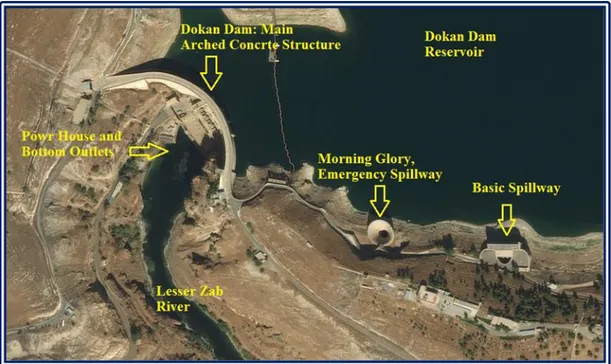
Dokan dam is the first dam that had been built in Iraq in the recent history; it is also the only concrete arched large dam in Iraq. The dam is located on Lesser Zab River in Dokan area and contributed with Dibis Barrage to feed Kirkuk strategic irrigation project. In the period before the era of Development Board, the Committee of Large Irrigation Projects had studied the proposed sites for a dam on Lesser Zab River. It was founded that among the selected sites, Dokan site is the most suitable because of the appropriate foundations and the existence of deep and narrow strait, which does not exceed 40 m width in drought season, and not exceeding 100 m width at height of 60 m. When Development Board commenced, Benny and Partners Company were commissioned to study the dam project. The company submitted its report in 1952, and after evaluation by Board of Experts and doing the amendments in accordance with their recommendations, the company prepared the final designs and contractual document. Then, dam construction contract awarded to French company Dumez-Ballot, other contractors were participated in the construction and supplying dam equipment. The dam was completed in June 1959. The hydroelectric power plant works were subsequently appealed and started in 1975 with five Francis turbine units generates 80 MW for each were they completed in 1979.(Al-Simawi, 2008; SMEC, 2006; Sousa, 1966).
The dam according to the final design is an arched concrete dam; the top level of the dam is 516.07 m a.sl. The tallest height of the dam body is 116 m, the length of the dam at the top with side abutments is 345 m and the radius of curvature is 120 m. The highest operating level of the Dokan reservoir is 511 m a.s.l. to impound storage of 6.8 billion cubic meters and a surface area of at that elevation equals to 270 km2, 6.1 billion cubic meters is the live storage. The minimum operational level is 469 m a.s.l. The dam has a Morning Glory spillway with a diameter of 40.26 m which is an emergency spillway works at elevation of 511 m a.s.l. and the maximum discharge is 1860 m3/s, this spillway built in the left shoulder of the dam, and beside on the left another spillway, which is the basic spillway, it works at elevation 496.5m a.s.l., this spillway has three openings with dimensions of (10×6.8) m. Both spillways divert the water through a tunnel buried in the left shoulder with a diameter of 11 m. There are also two bottom outlets lined with steel, where the discharge for each is 110 m3/s.(Al-Simawi, 2008; SMEC, 2006). Figure 7 shows a satellite view of Dokan Dam.
Figure 7: Shows a satellite view of Dokan Dam (Edited by Author; Esri n.d.).
In order to prevent the leaking on dam shoulders, two curtains of grouting had been implemented on both sides and up to depths of 300 m, the length of the first curtain is 1350 m on the left side, was later extended to 220 meters, and the length of the curtain on the right side is 1000 m.
Two inspection tunnels implemented on both sides, for the main tunnel on the left side it has a length of 450 m. A collapse occurred in sections of the left tunnel, especially during flood seasons and high levels in the dam lake, this was later concrete lined and completed in 1980. There is also number of tunnels on the left side as well as the main tunnel. It was implemented within the body of the dam. These tunnels can be accessed through the elevator on the left of the dam body (Al-Simawi, 2008).
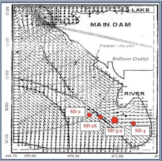
The inspection tunnels in the sides of the dam suffer from of filtration, especially after the 1988 flood. Benny and Partners Consultants, were contracted to evaluate the dam in 1998, it was concluded that the source of the leak was the joints between the rock formations. The dam also needs the maintenance for gates of the outlets. Other leaking locations were observed in the structural joints of the Morning Glory spillway, where in 2000 an inspection engineers sent down through the spillway by crane, and the scenes from inside were filmed (SMEC, 2006). Figure 8 shows the leakage locations in morning glory spillway of Dokan Dam.
Figure 8: leakage locations in morning glory spillway of Dokan Dam (SMEC, 2006).
Regarding the bathymetric survey of Dokan Lake, a survey has been made in 2014. The survey was carried out when the lake at storage elevation of 490 m a.s.l. However, results indicated that for the survey at this condition, the siltation volume was 209 million cubic meters, where the annual rate of sediments is 3.8 million cubic meters. Absolutely, the actual volume of sediments in the Lake is comparatively larger.(R. Hassan et al. 2019).
Despite of the above, it is unfortunate that the Ministry of Water Resources did not made any important treatments for this strategic dam, which is an important source of storage, knowing that there were enough funds achieved for the period of 2003 to 2014 and there were possibilities of contracting and training and the import of specialized materials and equipment easily. The action by the Ministry of Water Resources was to implement marginal and secondary effects projects such as construction of staff houses, forestation. While the essential works did not get the required efforts.
2.3 Adhaim Dam
Adhaim Dam is located on Adhaim River, which drains the water from the catchment that extends only inside Iraqi territories; the dam is located at the intersection of the Adhaim River with the Hemrin Hills. Building Adhaim Dam was presented since 1930s, later in the era of Development Board, Binnie and partners
studied the project as part of its study for the region. The French company Sogreah contributed later to the preparation of a study about Adhaim Dam in 1989. Binne and partners submitted a study about the project again in 1989.
The project construction started in 1989 and stopped due to the blockade after 1990. Then in the mid of 1990s, the Ministry of Irrigation adopted the reinitiating of works in the dam site, Euphrates Design Center prepared the detailed maps and contractual documents, several other entities were participated in the project, including Faw Engineering Company, which had carried out the drilling of the power and irrigation tunnel (Resources, 2005; Ministry of Irrigation, 2001).
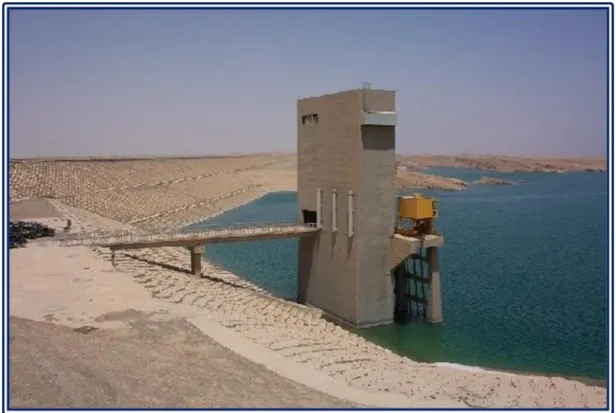
The dam project consists of the main dam body; a 3800 m long earth fill dam with clay core, maximum operational level is 131.5 m a.sl. with storage of 1.5 billion cubic meters, the tallest height of the dam body is 62 m. Side slope of the dam body from the upstream side has a riprap of concrete blocks with size rages (1-1.5) m3, these blocks were based on a layer of graded gravel sub base (Al-Simawi, 2008). Figure 9 shows a general view of the dam body intake structure.
The dam has ungated spillway with a length of 562 m and a maximum discharge of 1150 m3/s, at maximum flooding elevation of 143 m a.s.l. The dam also includes bottom outlets operating at a minimum level of 86 m a.s.l. which is the same level of river bet. In addition, there is a 50 m high intake structure that draws water to the tunnel excavated within the shoulders of the dam, this tunnel diameter is 4.5 m and it is 310 m long, and was lined with steel and concrete. The tunnel ends with two power outlets and one outlet for irrigation. It should be noted that the initial plan was the excavations of two tunnels in the adjacent hills, where it was reduced to one tunnel after re-evaluation of the design. The future power station includes two units with a capacity of 38 MW. The dam was opened in 1999 and the power plant is still incomplete. There are also needs for many devices and sensors required for safety and operation of dams, which was unavailable at the time of construction (Al-Simawi, 2008; USACE, 2003).
Figure 9: Adhaim Dam general view for the dam body intake structure (MoWR n.d.).
2.4 Darbandikhan Dam
Darbandikhan Dam is located on Diyala River at the Strait of Darbandikhan after the confluence of Tanjero and Sirwan tributaries, which form with some of small tributaries Diyala River. The idea of building a dam at the upper reach of Diyala River was put forward in the era of Coode Wilson and Heigh committees in 1930s and 1950s. After commencing of Development Board, Harza was commissioned to study the project and the geological investigations were entrusted to be carried out by Dr. C.L. Willis, where the alternatives was to build either concrete dam or an earth fill dam. The earth fill dam was chosen for technical and economic reasons. The implementation of the dam was initiated in 1956, where several companies took part in the project.
1. Darbandikhan Group of Companies is a consortium of companies including J.A. Jones Managing American Company, Inc. Texas Contractors Crop American Company, Inc. Beton Monierbau German Company, and C.H. Tompkins American Company to carry out the dam body and relevant work.
2. Cementation British company and Sondage Injection Forage French Company for drilling investigations.
3. Sainrapt & Brice French company to implement sections of the conversion tunnel.
The dam was completed in 1961 (Al-Simawi, 2008; SMEC 2006; Sousa 1966). Dam body has a clay core surrounded by a stone shell. The highest elevation of the
dam is 128 m and the width at the top of the dam is 535 m. The maximum operational level of the Darbandikhan dam is 485 m a.s.l., while the minimum operational level is 434 m a.s.l. with a design capacity of 3 billion cubic meter of which 2.5 billion is a live storage. The dam includes a spillway on the right side, the spillway has 3 curved gates with dimensions of (15×15) m, and spillway is divided into three sections that end with a flip bucket configuration. Spillway discharge is 5,700 m3/s at the maximum operational level, while the maximum discharge is 14,000 m3/s at maximum flood level of level 493.5 m a.s.l. (Al-Simawi, 2008; SMEC, 2006). Figure 10 shows a general view of Darbandikhan Dam from the upstream.
Figure 10: General view of Darbandikhan Dam from the upstream (MoWR n.d.).
The project also includes two tunnels on the right side, the first one which were utilized for river diversion has a diameter of 6 m and a length of 775 m, lined with reinforced concrete and ending with a section lined with steel with a diameter of 4.27 m. Beside, another tunnel with a diameter of 9 m and a length of 662 m, lined with reinforced concrete and the end part lined with steel for a length of 127 m. From the first tunnel of 6 m diameter, a pipe with 4.28 m diameter had branched and other 2 similar pipes were branched for the 9 m diameter tunnel. These three pipes deliver maximum discharge of 446 m3/s for irrigation outlets and hydroelectric power station. The discharges to tunnels are controlled by the intake structure which extends with spillway approach inside the like for a distance of 120 m. The intake structure has three openings with dimensions of (4×9) m and b level of the bottom of the intake is 410.5 m a.s.l., two openings discharge to the tunnel with a diameter of 9 m and the third one to the tunnel with a diameter of 6 m. The Intake is controlled by two steel gates have dimensions of (4.75 × 9.5) m.(Al-Simawi, 2008; SMEC, 2006; Resources 2005).
At the beginning of the project, a mini hydropower station were installed to meet the operation requirements of the dam, this station has a capacity of 1600 KW. Later, the main three hydropower units with Francis Turbines, these were installed with total capacity of 240 MW, the main hydropower units works done by Polensky and Zöllner German Company which had implemented the works, while Mitsubishi Company installed turbines and generators, the hydropower station started generating in 1990 for the first time (SMEC, 2006; USACE 2003).
The dam also includes two grouting tunnels inside the body of the dam. The right tunnel starts beneath the spillway near the left wall, beginning at elevation of 415 m a.s.l., then continues with bottom of dam body up to elevation 366 m a.s.l. and for a length of 175 m. The left tunnel extends from the surface and continues to a level of 373 m a.s.l. and for a length of 250 m. 75 meters between the right and left tunnels is the space between their both ends without tunneling.
Darbandikhan Dam was exposed to several post-operational technical problems. The first is the existence of the dam within active seismicity area. As noted, the geologist Dr. C.L. Willis omitted the concrete dam choice as there is fault in the river bed. Binnie and Partners had analyzed the dam's seismic safety, and they infer in the 1987 report that the Darbandikhan Dam exists within a fold in the south-west direction, where the convergence of Arab tectonic plate and the Eurasian Plate. The Company had accounted maximum credible earthquake forecasted according data records and the seismic stability of the dam, it was founded that the dam is safe regarding seismic safety, noting that the dam site experience an earthquake during the initial stage of filling.
Unfortunately, the dam does not include sensors to monitor seismic activity, and monitoring devices in Sulaymaniyah had stopped since 1991.
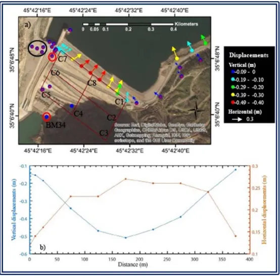
On November 12, 2017, the area nearby the dam in the Iranian city Sarpol Zahab was stroked by 7.3-degree earthquake, the epicenter was 30 km from Darbandikhan Dam. The body of the dam was directly affected, cracks occurred in the body of the dam. The quake was followed by 53 aftershocks. Surveys were conducted by the
Department of Surveying after the earthquake. There were cracks and settlements in some locations, especially at the top of the dam where the largest horizontal displacement was 27 cm in the center of the dam. On the left side, it reached 14 cm and on the right side 12 cm. Dam body at the top moved toward the center of the dam and to the northeast and north-west direction. While, the vertical displacement was varied from 50 cm in the middle of the top and it was varied from 15 to 45 cm at the sides, as shown in Figure 11 (Al-Husseinawi et al., 2018).
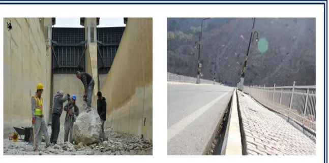
The movement included the rocks on the right side mountain, some of which were fallen near the dam and the administration building, and the most dangerous of what had fallen on the spillway channel. These rocks, which are large in size, pose a future danger in the event of repeated tremors or slippage due to unstable positions. The most important threat is the possibility of damaging the gates or important elements of the dam. Figure 12 shows the effects of the earthquake in late 2017 in terms of cracks in the body the main dam as well as the fall of rocks on the channel of the spillway (MoWR n.d.; “Darbandikhan Official Account on Facebook” n.d.). Among essential needs of the currently is to re-evaluate the safety of the dam and the level of storage under the current circumstances, after exposure the dam site to the earthquake that exceeded the estimations. According to the consultant Binnie and Partners in 1987, the dam could resist an earthquake up to 6.5 degrees, but what happened in 2017 is and earthquake of 7.3 degree at a distance of 30 km. A decision had been made to reduce the operational level, until the evaluation and recommendations were made by a technical authority. However, during the flood season of 2019 there was uncontrolled rise of the dam levels to the point where the spillway was operated.
Figure 11: Horizontal and vertical displacement in Darbandikhan Dam body after the earthquake in November 2017 (Al-Husseinawi et al., 2018).
Figure 12: Aftermath of the earthquake in November 2017 at Darbandikhan Dam; a) Right: cracks in the main dam body b) left: group workers are demolishing a stone that fallen in spillway chute from the adjacent mountain.
(“Darbandikhan Official Account on Facebook”n.d.).
Land sliding in the right side of the lake is one of the most important issues in Darbandikhan Dam, this has been diagnosed during the construction of the dam, and measures were taken in terms of increasing the side slope of the dam body. The sliding occurred after five years of lake operation, where the sliding observed at 300 meters from the body of the dam on the right side, it was founded in 1967 that the affected section extends 350 m long and 200 m wide with a depression for about 1.5 m. This sliding could make a mass of soil equivalent to 2 million cubic meters. The sliding was caused by precipitation occurred due to an intensive rainfall of 126 mm lasted seven days, and there was further rainfall between November 1969 and January 1970 (SMEC, 2006). Figure 13 shows the land sliding on the right of Darbandikhan Lake.
Figure 13: Land sliding on the right of Darbandikhan Lake (SMEC, 2006).
As a result, the French consultant Coyne & Bellier and Iraqi company Dar Baghdad to had assessed the situation regarding the sliding, and after the study, they submitted the designs and recommendations for remedies in 1975. The main conclusions is that if a failure to stabilize the land sliding occurred, the movement of the soil mass towards the dam body may cause to:
1. The closure of the spillway and the tunnels inlets, which obstructs the flow and this cause a great risk in the flood season.
2. When the lake reaching its maximum level, the land sliding might generates water wave that overflow above the body of the main dam.
In order to address this risk, the consultant recommended the following: 1. Reduce the size of the sliding block and reach to elevation of 448 m a.s.l. 2. Carry out soil stabilization and drainage systems for the area under
consideration.
3. Determination of 460 m a.s.l. as a minimum operating elevation for the dam lake.
4. Drilling 9 horizontal wells attached to pumping units to reduce moisture content in the affected area.
The implementation of the recommendations was initiated. Later, the dam was re-evaluated by the same company and Binnie and Partners until 2006, where Coyne & Bellier had presented recommendations after a new assessment of the dam. The recommendations are summarized as follows:
1. Determination of 450 m a.s.l. as a minimum elevation for the operation of the lake, considering that the amount of reduction water levels is no more than 10 cm/day.
3. There is urgent need to clean and maintain horizontal wells.
4. Continuous monitoring and recording of pumping data from wells (SMEC, 2006).
Another sliding was observed on the left side of the lake near excavations dumping site, 400 m away from the dam axis. On-site investigations have been carried out and measures have been taken such as drilling horizontal wells. This slippage and other slips at the edges of the roads leading to the dam do not pose a danger to the safety of the dam (SMEC, 2006).
In 2008, fish poisoning occurred in the lake parts near the confluence of the Tanjero tributary. The analysis indicated that heavy metals were present in the water samples, which are pollutants from industrial and municipal waste (Ararat et al., 2008) It should also be noted that the circumstances of the fighting led to the lifting of the gates of the dam and emptying the lake in 1988, the gates were later re-installed (Ministry of Irrigation, 1988).
2.5 Hemrin Dam
Hemrin Dam, Darbandikhan Dam, and Diyala Barrage bring out an integrated hydraulic system to exploit Diyala River and the investment of agricultural land within the boundaries of the river. The idea of constructing a dam at the intersection of Diyala River with Hemrin Hills has been discussed since the 1930s and several places have been investigated. As the catchment area downstream Darbandikhan dam up to Hemrin Dam equals to 12,760 km2, this encouraged to think about the benefits of building the dam. In 1959, during the study of Sir M. MacDonald Consulting Company to Diyala River basin, a Reservoir of 2.27 billion cubic meters capacity was proposed at elevation of 105 m a.s.l.
In 1966, Energoprojekt, a Yugoslavian company was commissioned to study the dam project and conduct the necessary investigations. The company submitted its report in 1970. After the flood of Diyala River in 1974, the dam project came back and Energoprojekt entrusted to carry out additional investigations and final designs. The study and designs were presented in 1976. The same year, Hydrogradnja Company had commenced to carry out the works of the project, while Energoporjekt cooperating with Iraqi authorities had conducted the supervision of dam construction. The dam was completed in June 1981.
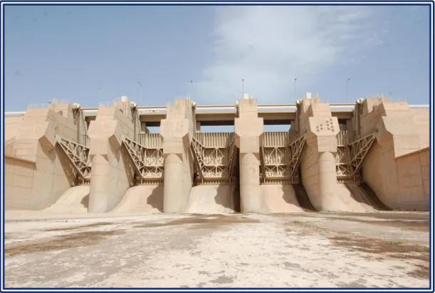
Hemrin Dam project consists of a main dam with a clay core, a height of 40 m and a length of 3,360 m. The operational level of Hemrin Dam is 104 m a.s.l., the total storage size 2.06 billion cubic meters of which 2.04 billion is live storage. The dam has a gated spillway controlled by five radial gates with dimensions of (10.6×12.5) m for each gate; the maximum discharge of the spillway is 6,800 m3/s at the highest flood level which is 107.5 m a.s.l. Figure 14 shows the spillway gates of Hemrin Dam. The dam has also 4 irrigation outlets with total discharge of 250 m3/s. There are also, hydroelectric plant with two Kaplan turbine units and total generation of 50 MW. Further, Inspection tunnels are inside the dam's body to lead to power house and irrigation tunnels (Al-Simawi, 2008; USACE 2003; Sousa 1966).
Figure 14: Spillway gates of Hemrin Dam, view from the downstream (MoWR n.d.).
In addition, there is also a fuse plug dam (Saddle Dam) which works as an emergency spillway with a discharge of 6,000 m3/s, where the water diverted to Saladin flooding course that lead to Schweicha northern depression (Ministry of Irrigation, 1988). The project also included Sadiyah protection dykes to protect the city of Sadiyah, adjacent to the lake of the dam. It should be noted that Khanaqin-Baqubah highway is passing inside the dam lake, the road has been built by constructing embankments in the lake, and there is a bridge in the middle allows the water flow between both sides of embankments.
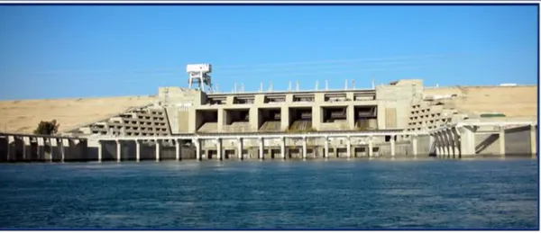
2.6 Haditha Dam
Habbaniyah project implementation for some extent had delayed the interest in the construction of a storage dam on the Euphrates River. The first attempt to introduce this subject was submitted by Iraqi Engineer Vahi Sevian in 1945, he proposed in his report build a storage dam in the Upper Euphrates reach. The proposal included two sites: the reservoir of the first dam extends from city of Rawa up to Syrian border, and the second proposal for a dam in Khan Al-Baghdadi, where two sites had proposed, one of them causing the inundation Haditha city. The subject came back to the forefront in 1958, when the area was investigated for the construction of a dam north of Hit city by an Iraqi team, where four sites had proposed on
Euphrates (Sousa, 1966).
The presence of the Soviet side in doing the irrigation plans and studies with the beginning of the republican era, hence; Technopromexport Company was entrusted to study a proposal of the dam on Upper Euphrates in Iraq. The preliminary suggestions included; first proposal is the building of two dams in Rawa and Haditha to avoid the flooding of the city of Anah and Rawa and, while second proposal is one dam in Haditha city, which is adopted.
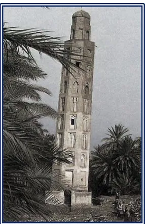
Studies and evaluation had been continued by Technopromexport and Swiss consultants. Finally, the contract was signed for the study and design of Haditha Dam between the Iraqi Ministry of Irrigation and Technopromexport Company on 26/11/1947. The study and additional investigations were completed in 1979. As a result of filling Haditha reservoir, water has to submerge Anah city and parts of the city of Rawa and many villages in the basin of the river, as well as many of the ruins in the area, where one of the most important is Minaret of Castle, which was dismantled and moved to a new location (Technopromexport, 1978; Saiid, 1978). Figure 15 shows the Minaret of Castle that had been moved to a new place. Also, the project included the construction of the new Ana city and the construction of new villages and farms for citizens who have to leave their homes. (Technopromexport, 1978)
Dam works started since 1977 and completed in 1988, the initial works was began before the completion of studies, such as roads, camp, and various infrastructures of the dam site. Detailed design and implementation of the hydroelectric plant were entrusted to the Yugoslav company Energoprojekt. While Technopromexport carried out the other designs and general supervision of the project in cooperation with Directorate General of Dams at the time. The use of Mealy Dolomite as a core material for the earth fill body of the dam was the first time used in the dam in the world, also, it's the first time to use asphaltic diaphragm with this materials for. This exceptional design required more time for the necessary tests and research (Adamo, Sissakian, Al-Ansari, Elagely, et al., 2018).
Figure 15: Minaret of Castle before moving due to inundation of Anah city (Saiid, 1978).
Haditha Dam project consists of the main dam with mealy dolomite core and asphaltic diaphragm in the middle, the core is shelled with mixed gravel, and the dam body lined with concrete from the upstream and it is lined with concrete blocks from the downstream as a riprap. The dam body composed of three parts, two earth fill parts and the middle concrete part. The right part has length of 3,230 m, the left part length is 495m, and the concrete part which constructed in the river section has a length of 580 m which includes most of the concrete parts such as spillway, power house, and bottom outlets. The tallest height of the dam body is 57 m and its total length is 8,950 m. The top of the dam elevation is 154 m a.s.l. The lake of the dam has a capacity of 8.2billion cubic meters at the maximum operational level of 147 m a.sl., the live storage is 5.8 billion cubic meter. Dam includes also the spillway which controlled by radial gates, the spillway consists of 6 openings of 16 m width, the maximum discharge of the spillway is 11,000 m3/s at elevation of 150.4 m a.sl., which is the maximum flood elevation. There are two bottom outlets with dimensions of (4×6) m and discharge of 500 m3/s, at the minimum operating level of 112 m a.s.l.(Simawi, 2008; Technopromexport, 1978; Adamo, Sissakian, Al-Ansari, Elagely, et al., 2018). Figure 16 shows the middle section of Haditha Dam.
Figure 16: Concrete Section of Haditha Dam, view from the downstream (MoWR n.d.).
Among the most important Haditha Dam installations is the hydroelectric plant, which includes 6 Kaplan turbine units with a capacity of 570 MW and a total discharge of 2.034 m3/s (Al-Simawi, 2008; Li et al., 2018).
The dam includes two grouting tunnels for both sides. Regarding the grouting, a curtain grouting was implemented with two lines and depths up to 80 m. Also, blanket grouting was carried out under the foundations of the dam and at depth of 10 m at the bed of the river, and 5 m deep under the dam. The seepage control system in the Haditha Dam is the Relief Wells, which are distributed in the downstream of the dam body. The dam is also provided with piezometers and sensors. (Adamo, Sissakian, Al-Ansari, Knutsson, et al. 2018).
In general, Haditha dam does not suffer from major problems, but needs for comprehensive technical evaluation after more than 30 years of operation and requires the maintenance and rehabilitation for piezometers.
In comparison with Mosul Dam, Haditha dam has successful designs and measures in term of foundations treatment, especially the overcoming of karstification problem. Where the measures taken in the Haditha Dam have succeeded more than what is achieved in Mosul Dam, and for the purpose of comparison between the two dams, the following points are presented:
1. The two dams are located on the Arabian plate, where the Mosul Dam is located within Fatha geological formation, while Haditha Dam is located within the Euphrates geological formation.
2. Both of the dams were built on sedimentary rocks where the karst activity is scattering beneath. Karst layer sequencing extends in Mosul dam site for 300 m, while it extends in Haditha Dam for 50 m.
3. Mosul Dam foundations have gypsum layers, while Haditha Dam foundations have limes layers, where the former is more soluble.
4. There was no timetable for conducting geological investigations in Haditha Dam, the work were done with all necessary to make the required tests or
investigations for developments, and it did not happen in Mosul Dam Project (Adamo, Al-Ansari, et al. 2018; Adamo, Sissakian, Al-Ansari, Knutsson, et al. 2018).
3. Small and Medium Storage Dams
Dozens of storage dams of medium and small capacity, and water harvesting dams are scattered throughout Iraq. These dams can be found in three main areas:
1. Mountainous and undulating region of Duhok, Erbil, Kirkuk and Sulaymaniyah governorates.
2. Eastern valleys area in Diyala, Wasit and Maysan governorates. 3. Western Desert area in Anbar, Najaf and Muthana governorates. 3.1 Small and Medium Storage Dams in the Northern Area
In Mountainous and Undulating areas, there are many dams, most of which were built after 2003. Data about number and existence of small dams in this territory is not precise; there are many dams, which are not registered by Iraqi Ministry of Water Resources. However, the most important known dams are:
1. Duhok Dam: is located Duhok valley, which is and earth fill dam with clay core. In 1978, the site of the dam was studied and designed by the Bulgarian company Akrocomplect. Implementation was started and completed in 1988. The dam is 60 meters high and length at the top is 613 m. The dam has a storage capacity of 52 million cubic meters. The dam includes morning glory spillway with a discharge of 81m3/s. There is also an irrigation outlet, a tunnel 2,035 m long and 2 m in diameter leading to the Duhok irrigation project.
2. Harawa dam: The dam is located on the Harawa Valley in Sulaymaniyah governorate. The dam study was prepared by FAO in 2002. It is 22.5 m high and 115 m long, with storage capacity of 0.764 million cubic meters. It was completed in 2007.
3. Azmar Valley Dams: seven weirs on Azmar Valley in Sulaymaniyah governorate. It was completed in 2006.
4. Khasa Chai Dam: it is located on Khasa Chai Valley in Kirkuk governorate. It was made from earth fills with clay core. The height of the dam is 58 m. It is 2,360 m long. The storage capacity of The Dam Lake is 46.36 million cubic meters. Implementation was started in 2009 and completed in 2014.
5. Qashkan Dam: it is located on Qashkan Valley in Duhok governorate. The Dam designs were prepared by Center of Studies and Designs, Iraqi ministry of water resources, and the Implementation was carried out by General Commission of Dams and Reservoirs. The dam is 270 m long and the size of the dam lake is 1 million cubic meters. The dam includes a 6 m3/s discharge outlet.
6. Shirin Dam: it is located on Shirin Valley in Lailan district. It is a 426 meter long earth fill dam. Storage capacity of 1.325 million cubic meters. It has an outlet of discharge 6.23 m3/s. As well as a 50-meter-long spillway, with discharge capacity 203 m3/s. The dam was completed in 2008.
7. Wand Dam: the dam is located on Wand River in Diyala governorate. The study on the dam was first submitted by the Bulgarian company Akrokompelket in 1979. It is 1342-meter-long earth fill dam, and 24 m high. It includes non-gated spillway of 35 m long and 140 m3/s discharge. The storage capacity of the lake is 37.82 million cubic meters. The dam was completed in 2013.
8. Belkana Dam: it is located on Belkana Valley in Kirkuk governorate. It is an earth fill dam with clay core. The dam is 277 m long, and the operational storage of the dam is 0.89 million cubic meters. The dam has an opening of discharge 6.46 m3/s. As well as, there is un-gated spillway of 35 m long and discharge 207.9 m3/s.
9. Shewasur Dam: the dam is located in Shwan district in Kirkuk governorate. It is 26 meters high and 333 meters long. Storage capacity is 4.45 million cubic meters. The dam was completed in 2016.
10. Bahiri Dam: the dam is located in Zawita area in Duhok governorate. It is one of the dams implemented by Duhok Irrigation Directorate and funded by a U.S. agency. The dam has a height of 18 m and storage capacity of 0.38 million cubic meters.
11. Chaq-Chaq Dam: it is located in Sulaymaniyah governorate. The dam designs were completed by the Bulgarian company Akrokomplekt and implemented with funding from the international organizations prior to 2003. The dam collapsed due to a high wave in 2005.
12. Chali Dam: It is located on the Samaqully Valley east of Erbil. The dam reservoir has a capacity of 8.6 million cubic meters. It was opened in 2018. 13. Durger Ajam Dam: it is located in Duhok governorate within the valleys of the
Khabur Basin. The dam is 15 m high and has a storage capacity of 0.15 million cubic meters.
14. Kasnazan Dam: the dam is located in Erbil governorate within the valleys of the Great Zab Basin. It is 10 m high and has a storage capacity of 0.32 million cubic meters.
15. Hamamuk Dam: it is located in the Koya area. The dam is 24 m high and the storage capacity is 0.35 million cubic meters.
16. Hassan Kanoush Dam: it is located in the Chamchamal area. The dam is 15 m high and storage capacity of 0.35 million cubic meters.
17. Bawa-Shaswar Dam: it is located in Koya area. The dam is 23 m high and storage capacity of 4.4 million cubic meters (Resources, 2005; Al-Simawi, 2008; USACE, 2003; Al-Simawi, 2010).
3.2 Small and Medium Storage Dams in Eastern Valleys
Eastern valleys are promising source of water storage and harvesting. The main problem in the region is the high rate of sediment load; hence, many dams were failed. More measures and fine tuning in selection of the dam site and erosion protection are needed. Other alternatives could be proposed as the underground reservoir, this requires a detailed investigations and data. The dams in this region are:
1. Qazaniyah Dame: it is located on the Harran Valley in Diyala governorate. The dam was studied by Euphrates Center and then studied by Tigris Center in 2004; both are directorate of Iraqi ministry of water resources. The dam is a 6.5-meter-high weir dam with lake of 0.9 million cubic meters capacity. It was completed in 2007. Also, the dam considered one of the dams that suffering from sedimentation.
2. Mandalay Dam: it is located on the Harran Valley in Diyala governorate. Studies were started in 2002 and completed in 2004. It is earth fill dam with clay core, 14 m high and 1,316 m long. The capacity of the dam lake is 3.63 million cubic meters. The dam has a 250-metre long spillway and discharge of 1,725 m3/s. Dam reservoir is almost full with sediments. Figure 17 shows a general view of Mandaly Dam Reservoir filled with sediments.
3. Shihabi Dam: it is located on Shihabi Valley in Wasit governorate. The dam was implemented by Al-Rafidain Company, where the dam is a 275 m long and 9 m high. It includes a 160 meter long spillway. The capacity of the dam lake is 0.8 million cubic meters. Like other dams in the eastern valleys, the dam is filled with sediments.
4. Dwerej Dam: the dam is located on the Dwerej Valley in Maysan governorate. The dam is a concrete weir with other retention dam in the form of Gabions. The dam was carried out by Al-Rafidain Company and is 510 m long and 9.5 m high. The capacity of the dam lake is 1.87 million cubic meters. It was completed in 2015.
5. Badra Dam: it is located on Badra Valley in Wasit governorate. It is a concrete weir of 3 m high and 800 meters long (Al-Simawi, 2008; Saeed, 2018).
Figure 17: General view of Mandaly Dam Reservoir filled with sediments. (MoWR n.d.)
3.3 Small and Medium Storage Dams in the Western Desert
Several dams were built during 1970s and 1980s in the western desert, the area is wide and promising for water harvesting and creating a new spot for living and agriculture in the middle of the desert. Unfortunately, the security issue in the region after 2003 resemble a challenge to continue with building such dams, the dams in this area are:
1. Husub Dam: the dam is located on Husub Valley, southwest of Najaf. The length of the dam is 1050 m and its height is 11 m. The size of the dam reservoir is 4.2 million cubic meters. It was completed in 2005.
2. Horan 2 Dam: it is located Horan Valley, northeast of the city of Rutbah. The dam is 650 m long and 14 m high and has a storage capacity of 4.9 million cubic meters.
3. Rutbah Dam: it is in the Western desert. It is an 848meter long earth fill dam, and the height is 19m. The dam has a storage capacity of 32 million cubic meters. It was completed in 1981.
4. Al-Ubailah Dam: it is in the Western desert. It is a 500-meter-long earth fill dam, and the height is 11.5m. The dam has a storage capacity of 4 million cubic meters. It was completed in 1973.
5. Al-Aghri Dam: it is in the Western desert. It is a 525-meter-long earth fill dam, and the height is 11 m. The dam has a storage capacity of 6 million cubic meters. It was completed in 1974.
6. Hussainiyah Dam: it is in the Western desert. It is a 512-meter-long earth fill dam, and the height is 13.25m. The dam has a storage capacity of 6 million cubic meters. It was completed in 1976.
7. Shibaijah Dam: it is in the Western desert. It is a 720-meter-long earth fill dam, and the height is 10.5m. The dam has a storage capacity of 8 million cubic meters. It was completed in 1977.
8. Rahaliyah Dam: it is in the Western desert. It is a 440-meter-long earth fill dam, and the height is 13 m. The dam has a storage capacity of 4 million cubic meters. It was completed in 1982.
9. Um Al-Tarfat Dam: it is in the Western desert. It is a 990-meter-long earth fill dam, and the height is 11.6 m. The dam has a storage capacity of 7 million cubic meters. It was completed in 1982.
10. Surry Dam: it is in the Western desert. It is a 570-meter-long earth fill dam, and the height is 5 m. The dam has a storage capacity of 0.3 million cubic meters. It was completed in 1976.
11. Abyadh Dam: it is in the Western desert. It is a 448-meter-long earth fill dam, and the height is 20 m. The dam has a storage capacity of 25 million cubic meters. It was completed in 2002.
3.4 Reservoirs in the natural depressions
Reservoirs in the natural depressions are one of the earliest irrigation projects in Iraq in the 20th century, where the main concern of the irrigation authorities in the first half of the twentieth century was to confront the flood by the most possible means and the least expensive. The pioneers in this context were the British engineer William Wilcox and British experts who Introduced studies in this tendency.
The idea is to find an escape in the shoulder of the river, to lead the water to a nearby natural depression. This depression utilized to maneuver in the river system operation to absorb the peak of flood waves before permeating into the Mesopotamian plain and causing a loss of human beings and properties. Early plans had been putted in place for the implementation of the first two main projects, Habbaniyah on the Euphrates river basin, and the Tharthar project on the Tigris river basin (Wilcox, 1917). Further, Schweicha reservoir and southern marshes were developed later to serve as the same function.
3.4.1 Habbaniyah Project
Habbaniyah project was considered for a period as the main project to protect from floods on the Euphrates River, until Haditha dam had been built. The project was proposed in the recommendations of Wilcox in 1911, but the implementation delayed due to circumstance of the First World War (Sousa, 1944).
Studies and designs continued after the formation of the Directorate General of Irrigation to utilize Habbaniyah depression, which is located east and southeast of the city of Ramadi. Then, implementation began in 1940, and due to the political events of May 1941 in Iraq, works were stood up. During the time between the formation of the modern state in Iraq and the 1940s, the Directorate General of Irrigation deliberately creates a fracture in the opening of the (Al Sitaieh) west of the city of Khalidiya city. Where for the period from 1924 to 1942, the openings were made eight times to pass the flood waves into Habbaniyah depression which was used to absorb part of the floodwaters (Sousa, 1966). The development of Habbaniyah Lake was initiated again in the early 1950s as part of the recommendations of the Heigh Advisory Committee; this committee was assigned to study the development of Tigris and Euphrates river basins (Commission, 1951). The implementation was carried out mainly under the supervision of Development Board, where this board commissioned in 1950 to invest the oil revenues in the development of Iraq infrastructure. The project was opened on 5/4/1956 (Sousa, 1966).
Figure 18 shows a general map of Habbaniyah project. The project consists the following:
1. Ramadi Barrage.
2. Warrar regulator and Warrar Canal. 3. Dhiban Regulator and Dhiban Canal. 4. Mijarrah Regulator and Mijarrah Canal. 5. Habbaniyah Lake.
6. Razzaza Lake or what is early know Abu Dibis depression.
Ramadi Barrage built on Euphrates River, upstream the city of Ramadi; the structure primary function is to raise water levels that required for operation of Warrar Regulator that divert water through Warrar Canal to Habbaniyah Lake. The Barrage length is 209 m, and it consist 24 gates, their dimensions are (6×8) m, and the design discharge is 3600 m3/s at level of 51.5 m a.s.l. The structure includes a navigational look with dimensions of (6× 40) and a fish ladder.
Figure 18: Habbaniyah project, a general map (D. Board 1955).
On the north-eastern edge of Habbaniyah Lake and Habbaniyah air base, the lake is connected with Euphrates River through Dhiban Canal, which has a length of about 9 km, the discharges out of the lake is regulated by Dhiban regulator, which consists five gates with a dimensions of (4.7×5) m and a discharge of 800 m3/s. Also, on the south-eastern Edge of the lake there is Mijarrah regulator, which controls the discharge of excess water through Mijarrah Canal to Razzaza Lake. Mijarrah regulator consists 8 openings, could reach a maximum discharge of 1900 m3/s (Resources, 2005; Al-Simawi, 2014).
Regarding the lakes, the level of the bottom of Habbaniyah Lake is 36 m a.s.l, and the maximum operating level of 51 m a.s.l. the lake total storage is 3.28 billion cubic meters of which 2.72 billion is a live storage, while the surface area of the lake at the maximum storage level is 425 km2. Pertaining Razzaza Lake or what was called Abu Dibis or the Salt Sea, the lake role is to work as a floodwater reservoir from Habbaniyah Lake, the lake bottom level is 17 m a.s.l. and the maximum storage capacity is 25.75 billion cubic meters at level of 40 m a.s.l., and a surface area of 1810 km2.(Sousa 1966).
Although Habbaniyah system has an important role to mitigate the dangers of flooding and provide water for irrigation requirements, the construction of Haditha dam and the future construction of Baghdadi dam have a negative impact on project
feasibility. Habbaniyah project among the most important proposed projects at the beginning of the twentieth century, at the time; no idea had been presented about a dam in the upper reach of Euphrates, where this had been raised during the stage of development board and the subsequent proposals of the Soviets consulting companies. One of Wilcox's proposals was also to re-use the storage of Razzaza Lake, as now Habbaniyah Lake utilized, but the detailed studies later do not recommended that.
The decline of water incomes in the Euphrates River had reflected on the water levels in Habbaniyah Lake, except the wet seasons. Also, this made a very large reduction in the limits and size of the Razzaza Lake, as shown in Figure 19 below. Finally, It's wise to mention that the drainage water of the Hussainiya irrigation project and parts of the Bani-Hassan irrigation project are pumped into Razzaza Lake.
Figure 19: Comparison of aerial photographs of the size of Razzaza Lake between 2003 and 2013 (Iraq 2013).
3.4.2 Tharthar Project
Tharthar project is one of the strategic projects that have been carried out in order to mitigate the flood danger threating the city of Baghdad, where the frequent floods that affected the city and its residents contributed to make the issue of flood protection in Baghdad as a priority of the Iraqi government and the Directorate General of Irrigation. William Wilcox had chosen the site to be an escape to prevent flooding of Baghdad. Studies continued after Wilcox, and the implementation did not start until the establishment of the Development Board, this also coincided with the flood in 1954, which is the last flood that was sank parts of the city of Baghdad,
this flood accelerated the decision to put in place the cornerstone of Tharthar Project (Sousa, 1966). The German company, Zublin, was entrusted to do the implementation of the structure, while Ransom and Rapier British Company carried out hydro-mechanical works. The works started in 1953, and the project was opened on 16/4/1956, where the water was passed to the Lake in the same month (Resources, 2005; D. Board, 1956). Figure 20 shows the elements of Tharthar and Habbaniyah projects. Tharthar project consists the following:
1. Samarra Barrage.
2. Tharthar regulator and Tharthar Canal. 3. Irwayah Canal.
4. Tharthar outlet regulator. 5. Division regulator.
6. Tharathar-Tigris and Tharathar-Euphrates Canals. 7. Tharthar Lake.
In order to divert the flood waves to the Tharthar depression, it was necessary to build a barrier on the Tigris River at the city of Samarra which is Samarra Barrage; it has a length of 252 m consisting of 17 openings (12×12) meters of dimensions. On the right side of the barrage, a hydro-power plant was installed with 14 units, with a maximum generation of 87 MW, the power station opened in 1971, there is also a fish ladder in the barrage. The maximum discharge of Samarra Barrage is 7000 m3/s. The project also includes 4 irrigation openings, with a diameter of 2.5m, these lead to underground buried pipes feed the Main Canal of the Ishaqi irrigation project.
Figure 20: Tharthar and Habbaniyah projects (MoWR, 2005) between 2003 and 2013 (Iraq 2013).
The important part of the project is Tharthar regulator, which is basically the backbone of the project to divert flood waves to Tharthar Lake, the maximum discharge of Tharthar regulator is 9000 m3/s, during the flood season in 2019m there is approximately 1000 m3/s passed through the regulator. The structure consists 36 openings with dimensions of (7×12) m. The regulator discharge water to Tharthar Lake via the 65-kilometer-long Tharthar canal.
In 1991, two gates from the left of the regulator were isolated to feed the Irwaiyah Canal, which is an independent path with a discharge of 250 m3/s directly connected with Tharthar-Euphrates Canal at the upstream of division regulator. The Irwaiyah Canal is about 97 km long. Figure 21 shows the satellite view of Samarra Barrage and Tharthar Regulator (Resources, 2005; Al-Simawi, 2014).
Figure 21: Satellite view of Samarra Barrage and Tharthar Regulator (Edited by Author; Esri n.d.).
The consultants who studied the Tharthar Lake did not agreed about the reuse of the reservoir storage during drought season. However, the decision finally made to dig the canals connecting Tharthar Lake with Tigris and Euphrates rivers. Started in 1972 Tharthar outlet regulator construction begun at the southern edge of the lake, and opened in 1976, the regulator includes 6 openings with a dimension of (6×8) m, and the maximum discharge of 1100 m3/s. The bottom level of the regulator is 40m a.s.l., below that is the dead storage (Sousa, 1966; Al-Simawi, 2014; Construction, 1989).
At the lower edge of Tharthar Lake and starting from the outlet regulator. Tharthar-Euphrates Canal start in a linear path for a 26.8km till the division regulator, there, the division regulator comprised two partitions; on the left the first partition comprises 4 gates with dimensions of (8×7) m and a discharge is 600 m3/s, at this regulator, Tharthar-Tigris Canal starts and confluence Tigris River upstream of Baghdad city. The other part which built perpendicular to Tharthar-Euphrates Canal has 4 gates with dimensions of (8×7) and a discharge is 500 m3/s, this regulator control the discharges on the Tharthar-Euphrates Canal which confluence with Euphrates River near Habbaniyah city. The length of the Tharthar-Euphrates Canal downstream the division regulator is 9.5 km long and the water was first diverted through the canal to the Euphrates River in 1976. Tharthar-Tigris Canal continues to the east for 28.5 km, at this station, the drop regulator built, the function of regulation is to control the elevations and discharges, the drop regulator includes 4 openings with dimensions of (8×12.85) m and a discharge of 600 m3/s; Figure 22 is a downstream view of drop regulator. Downstream this regulator, the Tharthar-Tigris Canal continues for 36.5 km. Water was diverted through the canal for the first time in 1988 (Al-Simawi, 2014; Construction 1989).
Figure 22: Downstream view of drop regulator on the Tharthar-Tigris Canal (MoWR n.d.).
Tharthar Lake is one of the largest natural depressions in the region, where it's located west of Samarra, the lake has a pear shape with a maximum length of 120km and a maximum width of 45km. Tharthar depression is a natural feature believed to be caused due to karstification and continuous sinking of a subsurface graben. The bottom elevation of the lake -3 m a.s.l, and the maximum elevation is 65 m a.s.l. (Sousa, 1966; Sissakian, 2011). The Lake is a natural continuation of Tharthar valley, which starts from the Sinjar Mountains, which runs north and then to the northwest, this valley drain the southeastern foothills of Sinjar Mountain, and there was a proposals about utilizing the catchment and harvesting the water in the valley before reaching Tharthar Lake, unfortunately; there were no measuring station for this promising valley. Nevertheless, an estimation during the rainy season 2012-2013 revealed that the upper reach of the valley before the confluence with Tharthar Lake has income about 141.7 million cubic meters at that season (Saleh, Abdulrahman, and Salih, 2017).
Tharthar Lake maximum capacity is 82 billion cubic meters at the level of 65 m.a.sl. The water has been diverted for many years, and the rate of incomes of the lake had been decreased after the commissioning of Mosul dam, and will decrease further after the building of Bekhme and Makhoul Dams.
Ones of the main issues in Tharthar Lake are the evaporation and high salt content. The surface area of the lake is 1600 km2 at the bottom level of outlet regulator which is 40 m a.s.l., it rising to 2700 km2 at the operational maximum level 65 m a.s.l., also, evaporation at the maximum capacity is 7.4 billion cubic meter per year. Additionally, the high rate of evaporation, causes high saline concentrations of water in the lake, this is also caused mainly due to saline leaks from the bottom of the lake. The Directorate General of Industry analyzed water samples from Tharthar Lake when it was first started in operation. It was estimated that the lake had had a solution close to the saturation level before opening the canal for the first time in 1956 where the estimated quantity was 100 million cubic meters. After closing the canal after the first flood water passing, where it was closed on 5/5/1956, and after 24 days of closure, the salts concentration was 3.700 ppm, this increased on 20/11/1956 to 9360 ppm. After calculating the evaporation salts residual, it was concluded that the solubility of salts from the lakebed, most of which is sodium chloride, is the largest source of salinity in Tharthar Lake. (Industry 1957).
Energoprojekt company conducted in 1971, a study to analyze the salt balance within Tharthar Lake after thirteen years of commissioning, i.e; the period of 1957-1969. The results manifested that the evaporation from the lake is an additional factor affecting the salt accumulation, as the major contributor is the solution of the salts from the Lakebed. Table 1 shows an approximate contribution of various factors in increasing salt concentration within Tharthar Lake (Consulting Engineering Bearue, 2011).
Table 1: An approximate contribution of various factors in increasing salt concentration within Tharthar Lake (Consulting Engineering Bearue, 2011).
Salt balance in Tharthar Lake Water capacity billion m3 Total quantity of salt 1012 p Concentration ppm % Old Tharthar depression till Jan., 1, 1957. 1.5 15.200 220 14.7 Diverted Tigris river from Jan., 1, 1957 to Dec., 31, 1969. 68.6 17.200 250 16.7 Evaporation losses during 13 years period 30.6 7.600 100 6.7
Bed and wall of depression lixivation from Jan., 1, 1957 to Dec., 31, 1969. - 65.000 930 61.9 Salt in the Tharthar Dec., 31, 1969. 70.1 105.000 1500 100
Another aspect of Tharthar Lake is the proximity of the inlet mouth to the outlet regulator. This is reflected negatively on the mixing and the homogeneity of salt concentrations in the lake. (Al-Ta’i, 2015).
The years of drought that Iraq had experienced in 1999 and 2001, and after reaching the level of the lake below the bottom of the outlet regulator, the proposal of installing a pumping station to use the dead storage was presented. This idea was raised again after the dry season 2018, but the pumps did not install yet, although preparation works was partially completed.
3.4.3 Shweicha Depression
Shweicha depression is located east and northeast of Kut city, with the following main valleys feeding the depression: Wadi Harran, Wadi Shushrin, Wadi Al-Obeid, Wadi Tarsakh and Wadi Badra. The highest discharge achieved by these valleys is in the Wadi Badra where it reached 3500 m3/s (Saeed, 2018).
The depression bordered from the west by the chordal dykes that protects the city of Kut and Baghdad-Kut highway, the depression expands from the eastern side to some limits depending on season.
The idea of exploiting this depression was started at the beginning of the recommendations of the irrigation projects in the Wilcox proposals and the