Mälardalen University Press Licentiate Theses No. 235
TOWARDS ACCELERATED SIMULATIONS FOR FLUID FLOW
AND HEAT TRANSFER OF LARGE INDUSTRIAL PROCESSES
Md Lokman Hosain 2016
School of Business, Society and Engineering
Mälardalen University Press Licentiate Theses
No. 235
TOWARDS ACCELERATED SIMULATIONS FOR FLUID FLOW
AND HEAT TRANSFER OF LARGE INDUSTRIAL PROCESSES
Md Lokman Hosain
2016
Copyright © Md Lokman Hosain, 2016 ISBN 978-91-7485-264-6
ISSN 1651-9256
Summary
The manufacturing sector is one of the biggest energy consumers. The iron and steel markets in China are growing very fast. Several studies have been performed to evaluate the Chinese steel sector in terms of energy savings and CO2 emissions. The results of the studies showed that the major energy
sav-ings expected within 2020 and 2030 timeframe will be from industrial fur-naces in steel mills. For the Swedish steel industry, it is important to be very efficient in order to remain competitive. The hot rolling process in the steel industry is a long process, where big slabs are heated in a furnace above the recrystallization temperature to roll the metal into a thin sheet and then the sheet is cooled at the Runout table using water. The amount of energy used during the process directly influences the price of the products. Moreover, the government policy on energy usage and CO2 emissions, the competitive
mar-ket and the water scarcity, demand an optimal process operation to reduce energy consumption and greenhouse gas emission. Computer simulation is the best and most convenient way to approximate real-world processes; therefore, there is a need to have a real-time online simulation tool for process optimisa-tion, decision support and diagnostics in different industries.
Computational fluid dynamics (CFD) is a robust tool for simulating almost any kind of real-world process related to fluid flow, heat transfer and combus-tion. However, simulating real-world processes in real-time using CFD is very challenging due to the complexity involved in the physical phenomena stud-ied. In this thesis, CFD simulations have been performed in small scale to understand the physics and perceive the complexity involved in the heating process of steel slabs and the cooling process of the steel sheets at hot rolling steel industries. The results from the simulations are successfully validated using experimental and theoretical results published in open literature. Past experience suggests using mesh based commercial CFD solvers for simulating industrial processes, only if accurate and detail results are desired. However, the computational performance of these solvers shows limitations from a real-time perspective and indicates the need for alternative CFD methods and solv-ers. In the literature review performed as part of the first stage of this work, we have identified different alternative methods which can be used to perform CFD simulations in real-time or near real-time for large industrial processes. The thesis discusses the limitations of different types of CFD methods and points out the difficulties and challenges in utilising these methods for simu-lating large industrial processes. Our preliminary simulation work brings light towards the goal of multi-phase multi-physics real-time simulations.
Sammanfattning
Tillverkningsindustrin är en av de största energikonsumenterna. Järn och stål-industrin i Kina växer väldigt fort. Flera studier har genomförts för att utvär-dera den kinesiska stålindustrisektorn vad gäller energieffektivisering och ut-släpp av CO2. Resultaten av studierna visade att de stora energibesparingarna
som kan genomföras under åren 2020–2030 kommer från industriella ugnar i stålverken. För den svenska stålindustrin är det viktigt att vara mycket effektiv för att bibehålla konkurrenskraft. Varmvalsningsprocessen i stålindustrin är en lång process, där stora skivor hettas upp i en ugn över den temperatur där materialet rekristalliseras och metallen valsas sedan i tunna skivor. Skivorna kyls sedan på utrullningsbordet med vatten. Energimängden som används un-der processen påverkar direkt priset på produkterna. Dessutom kräver stränga statliga bestämmelser, en konkurrenskraftig marknad och bristen på vatten op-timala processförhållanden för att reducera energikonsumtionen och utsläppen av klimatgaser. Datasimulering är det bästa och mest pålitliga verktyget att approximera en verkliga processer. Det finns därför ett behov att ha ett online simuleringsverktyg för processoptimering, beslutsstöd och diagnostik i olika industrier.
CFD-simulering (Computational fluid dynamics) är ett robust simulerings-verktyg för nästan alla typer av verkliga processer relaterade till vätskeflöde, värmeöverföring och förbränning. Dock är simulering av verkliga processer med CFD mycket utmanande på grund av komplexiteten i de fysikaliska fe-nomenen som ska studeras. I den här avhandlingen har CFD-simulering an-vänts i liten skala för att förstå fysikaliska egenskaper och komplexiteten i värmningsprocesser av stålskivor och kylningsprocessen av de tunna stålplå-tarna vid varmvalsningsprocessen i stålindustrin. Resultaten från simulering-arna är framgångsrikt validerade från experimentella och teoretiska resultat publicerade i litteraturen. Tidigare erfarenheter föreslår nätverksbaserade kommersiella CFD-verktyg för att simulera industriella processer om korrekta och detaljerade resultat ska fås. Dock är prestandan för dessa verktyg begrän-sade ur ett verklighetsperspektiv och indikerar behovet av alternativa CFD-metoder och verktyg. Det första steget i detta arbete var att genomföra en lit-teraturgenomgång av tidigare studier. Vi identifierade då alternativa metoder som skulle kunna användas för att genomföra CFD-simulering i realtid och i nära realtid för stora industriella processer. Avhandlingen diskuterar begräns-ningar av olika CFD-metoder och synliggör svårigheter och utmaning i att utnyttja dessa metoder för att simulera stora industriella processer. Vårt preli-minära simuleringsarbete är ett litet steg på vägen i målet att producera flerfa-siga och multifysikaliska realtidssimuleringar.
List of papers
This thesis is based on the following papers, which are referred to in the text by their Roman numerals:
I. Hosain, M.L., Bel Fdhila, R., Daneryd, A., 2015. Heat transfer by liq-uid jets impinging on a hot flat surface. Appl. Energy 164, 934–943. doi:10.1016/j.apenergy.2015.08.038
II. Hosain, M.L., Bel Fdhila, R., Sand, U., Engdahl, J., Dahlquist, E., Li, H., 2016. CFD Modeling of Real Scale Slab Reheating Furnace, in: 12th International Conference on Heat Transfer, Fluid Mechanics and Thermodynamics, HEFAT2016.(Manuscript accepted)
III. Hosain, M.L., Fdhila, R.B., 2015. Literature Review of Accelerated CFD Simulation Methods towards Online Application. Energy Proce-dia 75, 3307–3314. doi:10.1016/j.egypro.2015.07.714
Contents
1 Introduction... 1
1.1 Background ... 1
1.2 Research gaps ... 2
1.3 Objective of the thesis ... 3
1.4 Contributions of the thesis ... 4
1.5 Thesis outline ... 5
2 Summary of appended papers ... 6
3 Literature review ... 8
4 Methodology ... 11
4.1 Industrial process ... 11
4.2 Modelling... 12
4.2.1 Numerical model development techniques ... 13
4.2.2 Meshing techniques ... 15
4.2.3 Mathematical models ... 17
5 Results and discussion ... 20
5.1 Results ... 20
5.1.1 The jet-cooling problem ... 20
5.1.2 Furnace ... 25 5.2 Further remarks ... 26 6 Conclusions... 29 7 Future work ... 31 References ... 32 Appendix ... 35 Papers ... 37
List of figures
Figure 2.1: Schematic showing the relationship between the research topics
and the papers ... 7
Figure 3.1: Hierarchical classification of methods in CFD ... 9
Figure 4.1: Hot rolling process in steel industries ... 11
Figure 4.2: Methodological approach for CFD simulations ... 12
Figure 4.3: Single jet case in 3D. (a) Full 3D domain (b) 3D model with dimensions and boundary conditions ... 14
Figure 4.4: Two-jet case in 3D (a) full 3D domain and (b) 3D model with dimensions and boundary conditions ... 14
Figure 4.5: Whole furnace (side view) in 2D showing different zones, burners and thermocouples (TC) in Zone1 ... 14
Figure 4.6: Numerical domain with boundary conditions (BC) (a) Burner configuration in 3D (b) Numerical domain with single burner (c) Zone 1 and 2 in 3D (d) Burner configuration in 2D ... 15
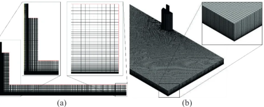
Figure 4.7: Mesh for impinging jet cooling model (a) 2D-axisymmetric model (b) 3D model ... 16
Figure 4.8: Mesh for the numerical domain (3.4 million cells) (a) burner (b) the whole domain ... 16
Figure 5.1: Impinging jet, I: the stagnation zone, II: the laminar boundary layer, III: the momentum boundary layer reaches the film surface ... 21
Figure 5.2: Interface of the water jet for different inlet velocities ... 21
Figure 5.3: Comparison between simulation and correlation (4.1) of the minimum jet diameter (𝐷𝐷𝐷𝐷𝐷𝐷𝐷𝐷) ... 22
Figure 5.4: Comparison of film thickness with correlation (5.2) ... 23
Figure 5.5: Nusselt number at stagnation point ... 23
Figure 5.6: Nusselt number comparison for single jet and two-jet case ... 24
Figure 5.7: Heat transfer performance (a) Total temperature field over the plate in kelvin (K) for Single-jet (b) Total temperature field over the plate in kelvin (K) for Two-jet ... 24
Figure 5.8: Path lines of the velocity (ms-1) on the cross section plane in the middle of the domain showing the recirculation ... 25
Figure 5.9: Surface temperature of the steel slab ... 26
List of tables
Table 1: Relation between the papers and the research questions ... 7 Table 2: Mesh information for all the models ... 17 Table 3: Nusselt number correlation at stagnation point for turbulent jets
... 20 Table 4. Comparison between average temperature of thermocouples and
simulation ... 26 Table 5: CPU time for a converged solution ... 27
Nomenclature
Abbreviations
CFD Computational Fluid Dynamics
CPU Central Processing Unit
CUDA Compute Unified Device Architecture
FDM Finite Difference Method
FEM Finite Element Method
FFD Fast Fluid Dynamics
FMM Fast Multipole Methods
FVM Finite Volume Method
GPGPU General Purpose Graphic Processing Unit
HPC High Performance Computing
LBM Lattice Boltzmann Method
LPG Liquefied Petroleum Gas (Propane)
MAC Marker And Cell
MPI Message Passing Interface
OpenCL Open Computing Language
OpenMP Open Multi Processing
POD Proper Orthogonal Decomposition
RANS Reynolds Averaged Navier Stokes equations
ROM Reduced Order Modelling
ROT Runout Table
RQ Research Question
SPH Smoothed Particle Hydrodynamics
SVD Singular Value Decomposition
Symbols
Cp [J/(KgK)] Specific heat capacity
C [-] Constant d [m] Nozzle diameter D(Z) [m] Jet diameter Dmin [m] Minimum D(Z) E [J] Total energy f
𝑓𝑓̅ [-] [-] Mixture fraction Mean mixture fraction g [m/s2] Gravitation constant
𝐺𝐺𝑘𝑘 [-] Generation of turbulence kinetic energy due to the
mean velocity gradients h [W/m2K] Heat transfer coefficient
h(r) [m] Liquid film thickness K [W/mK] Thermal conductivity k [m2/s2] Turbulence kinetic energy
Nu [-] Nusselt number
Nu0 [-] Nusselt number at stagnation point
p [Pa] Pressure Pr [-] Prandtl number q'' [W/m2] Heat flux r [m] Radial position r1 [m] Radius of region I r2 [m] Radius of region II
r3 [m] Radius of region III
Red [-] =𝜌𝜌𝑈𝑈𝑓𝑓
𝜇𝜇 , Reynolds number based on d
S [J] Source term
T [°C] Temperature
u [m/s] Velocity
𝑢𝑢′ [m/s] Fluctuating velocity Uf [m/s] Fluid velocity at inlet
x [m] Cartesian axis direction
𝑌𝑌𝑀𝑀 [-] Contribution of the fluctuating dilatation in
com-pressible turbulence to the overall dissipation rate z0 [m] Distance between nozzle and strip
Z [m] Distance downward from the nozzle 𝑍𝑍𝑖𝑖 [-] Elemental mass fraction for element i
Special characters
ij [-] Kronecker delta
ε [m2/s3] Turbulence dissipation rate
µ [Kg/ms] Dynamic viscosity [m2/s] Kinematic viscosity
[kg/m3] Density
ij [-] Stress tensor
Subscripts
Turbulence dissipation rate
eff Effective
f Fluid
fuel Fuel stream inlet
h Heat
∞ Free stream fluid
k Turbulence kinetic energy
m Mass
min Minimum
µ Dynamic viscosity
ox Oxidizer stream inlet
s surface
t Turbulent
user User
Acknowledgements
This Licentiate thesis is conducted at the Future Energy Center, Mälardalen University, Västerås, Sweden with financial support from The Knowledge Foundation, SSAB, ABB, Mälarenergi and Eskilstuna Energi & Miljö.
My first and foremost thanks goes to my principal supervisor Prof. Rebei Bel-Fdhila for his continuous and invaluable guidance, support, suggestions and inspiration throughout this thesis work.
I would like to acknowledge my co-supervisor Prof. Erik Dahlquist and Dr. Hailong Li for their guidance and support during my thesis work.
I would also like to thank Dr. Konstantinos Kyprianidis for reviewing this Licentiate thesis and for his valuable comments and suggestions.
My special thanks goes to my colleagues and friends at my department for different fruitful discussions.
Finally, I would like to thank my beloved wife and my parents for all kind of support and inspirations I got from them during my studies.
1
1 Introduction
1.1 Background
Fluid flow and heat transfer analyses are very important for many industrial processes and products, such as the runout table cooling process in the hot rolling steel industries (Cho et al., 2008; Mishra et al., 2015; Vakili, 2011), industrial furnaces and boilers (Dong, 2000; Stopford, 2002; Zhang et al., 2010), cooling of microchips and high voltage products (Soon and Ghazali, 2008; Subramanyam and Crowe, 2000; Winder, 2004). Competitive markets in terms of pricing and lifetime of products and environmental aspects moti-vate industries to continuously investigate and upgrade their products and pro-cesses. Greenhouse gas emission policy and energy usage in the production phase directly influence the price of different industrial products. Therefore, there is a demand for a reduction in the energy usage in industries by optimis-ing their products and processes. The hot rolloptimis-ing steel industry is one of the biggest energy consumers and has a great potential for energy savings (Li and Zhu, 2014). In addition, it usually depends on energy from fossil fuels, and thus reducing this energy usage would also have a direct effect on greenhouse gas emissions. It is crucial to understand the processes and the phenomena involved before they can be optimised.
Computational Fluid Dynamics (CFD) is a robust tool used to simulate and analyse the fluid flow and heat transfer in industrial processes since it can capture the complex features of fluid flow and heat transfer accurately. A real-time CFD-like tool for online use would represent a huge advance for optimi-sation of industrial process operations. In CFD, the computational domain is usually discretised using a large number of mesh cells, and the accuracy of the solver is completely dependent on the number of cells and how well the mesh is refined locally to capture the interesting factors in the simulation domain. Therefore, CFD simulations require a large amount of computational power because a large system of nonlinear equations has to be solved over all the mesh elements simultaneously. CFD has been used to simulate a full industrial furnace using a very coarse mesh to obtain the overall flow pattern in which all the small scale features are ignored (Huang et al., 2008; Kim et al., 2000; Morgado et al., 2015). In the past few decades, technological advances in par-allel computing have made it possible to simulate and investigate different industrial products and processes using CFD. However, simulating large in-dustrial processes in detail, by refining all the local flow factors, using the
2
methods implemented in commercial CFD packages is still beyond the avail-able computational capacity. The current situation demands alternatives to commercial CFD packages to simulate large industrial processes in real time and use the results for online control systems.
There are two ways to accelerate CFD simulations, using (I) High Perfor-mance Computing (HPC) resources, and (II) fast numerical methods. For the CFD simulations presented in Paper I (Hosain et al., 2015) and Paper II (Ho-sain et al., 2016), HPC is used to accelerate the computation while using the most popular and reliable mesh based method implemented in the commercial CFD software ANSYS FLUENT. The performance of the solver shows that it is still very far from a real-time simulation. An extensive literature survey car-ried out in Paper III (Hosain and Fdhila, 2015) shows that there are methods that can significantly speed up the mathematical operations while maintaining good accuracy. However, most of the fast methods are still under development and not suitable for all types of problems related to fluid flow and heat trans-fer. The level of accuracy obtained through these methods is often good enough to analyse a process or to use it for online control during the process operation. The ideal scenario would be to use these fast methods together with the recent HPC technology GPGPU (General Purpose Graphics Processing Unit) to accelerate the mathematical operations to bring the simulation on-line.
1.2 Research gaps
The most popular methods for performing CFD simulations are the Finite Vol-ume Method (FVM) and the Finite Element Method (FEM), which are purely mesh based methods that are completely dependent on the mesh. Mesh based solvers require a large number of cells or locally refined cells to resolve inter-esting local flow features. This requirement for large mesh is a serious limita-tion for mesh based solvers to be used for real time simulalimita-tions. Moreover, industrial problems where fluid-fluid or fluid-solid interactions take place are always complicated and difficult to solve using mesh based solvers. This is because one needs to predict the flow mixing and interfaces during the pre-processing and to resolve the local meshes, which is often cumbersome. The difficulty and challenges in solving industrial problems with fluid-fluid and fluid-solid interactions have not been rigorously discussed in the open litera-ture.
It is often not very obvious how a process should be formulated into a nu-merical model in order to make it solvable. Therefore, one needs to analyse a process before the appropriate boundary conditions (e.g. symmetry or peri-odic) can be chosen to reduce the numerical domain size or to cover more of the process. These approaches are discussed in this thesis.
3 Mesh based solvers have been widely used to solve CFD problems for sev-eral decades. The traditional solvers based on FVM or FEM are accurate and robust for a wide range of CFD problems. A full 3D industrial furnace was simulated by Huang et al.(2008) and Morgado et al.(2015) using very coarse mesh. However, the performance of the solver was still far from that of a real-time simulation. A simplified model was considered by Marino et al.(2002) to simulate a furnace in real time. However, the model was developed in 2D, which cannot represent the 3D effects of flow mixing and combustion accu-rately. Up to now no real-time simulations in 3D for industrial processes based on FVM or FEM have been published. Simplified particle based methods like Smooth Particle Hydrodynamics (SPH) (Auer, 2008; Krog and Elster, 2012) and hybrid methods like Lattice Boltzmann Method (LBM) (Geveler et al., 2011; Liao and Jen, 2011) are slowly emerging and increasing in popularity in the CFD community because of their speed. These methods are currently being widely used for visual fluid effects in movies and video games where the accuracy is not that important. The limitations of these methods for indus-trial processes are therefore still unknown due to the lack of study. Further-more, there has been almost no comparison between the methods in the liter-ature aimed at selecting the right method for a particular application.
The research questions (RQ) addressed in this licentiate thesis include: RQ 1
What are the difficulties and challenges in modelling large industrial pro-cesses where fluid-fluid or fluid-solid interaction takes place?
RQ 2
How can large scale complex problems be formulated to be solvable? RQ 3
What are the key factors that limit the online use of mesh based CFD sim-ulations and how might these be overcome?
RQ 4
What are the alternatives to mesh based CFD simulation methods that can provide significant speed-up for online use?
1.3 Objective of the thesis
The overall objective of the thesis is to simulate a subsection of large industrial processes using the available methods implemented in commercial CFD pack-ages to identify limitations and challenges from the real-time simulation view-point. Another objective is to perform an extensive literature review to find
4
alternative methods that can provide significant speed-up to enable simula-tions to be run in real time.
The goals of the thesis can be explicitly described by the following points: To perform numerical simulations for different industrial processes
re-lated to multiphase fluid flow, heat transfer and combustion. Moreover, to validate the results using data obtained during the process operation, data published by other researchers or theoretically.
To simplify the original process into a smaller numerical domain, by im-posing boundary conditions and assumptions to represent the reality and make it numerically solvable.
To discuss the usefulness and limitations of the methods commonly used in commercial CFD packages from the real-time simulation perspective. To find alternative methods to achieve real-time simulation based on the
literature review.
1.4 Contributions of the thesis
The author of this thesis developed all the models used for the simulations, performed all the simulations presented in Paper I and Paper II and reviewed the relevant literature presented in Paper I, Paper II and Paper III under the supervision of the main supervisor and the co-supervisors. The author wrote all the appended papers in this thesis and served as first author.
The overall contribution of the thesis can be briefly summarised as follows: Numerical modelling to better understand the fluid flow and heat transfer phenomena at the Runout Table (ROT) cooling process for hot rolling steel industries.
A reduced model is developed to represent and simulate the full preheat-ing zone of a full scale industrial furnace to provide a clear understandpreheat-ing of complex flow mixing and combustion associated with that zone. Identification of the difficulties and challenges in modelling large scale
industrial processes in real time.
A detailed literature review is performed to identify CFD methods that can lead to real-time simulations to provide results for online applications in industrial processes.
5
1.5 Thesis outline
This thesis is written based on the appended papers and it contains the follow-ing chapters:
Chapter 1 Introduction
This chapter presents the thesis background, research gaps, ob-jective of the thesis, contribution of the thesis and the thesis out-line.
Chapter 2 Summary of appended papers
The included papers are briefly summarised and the relationship between the research topics and the papers are presented in this chapter.
Chapter 3 Literature review
This chapter presents a literature review on CFD simulations in the field of multiphase flows and heat transfer. It also presents a literature review on available accelerated CFD methods.
Chapter 4 Methodology
The overall methodology and the models used for the simulations are described in this chapter.
Chapter 5 Results and discussion
This chapter presents the main results from the simulations.
Chapter 6 Conclusions
This chapter presents the major conclusions of the thesis.
Chapter 7 Future work
6
2 Summary of appended papers
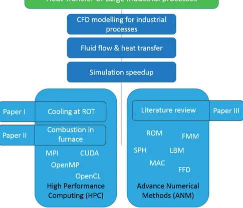
The included papers are briefly summarised in this chapter, along with a sche-matic showing the relationship between the research topics and the papers. Summary of Paper I:
In this paper, numerical models are built to simulate single and multiple water jets impinging on a hot flat surface to analyse the heat transfer from the surface to the water jets. Techniques to develop the numerical models are discussed and presented (RQ2). A 3D model to simulate a single jet and a 3D model to simulate two jets are presented to analyse the fluid-fluid and fluid-fluid-solid interactions and these models are validated using the-ory and published data (RQ1). In addition, a 2D axisymmetric model is developed to analyse the influence of the flow rate on the heat transfer and a correlation for the radial position of the maximum Nusselt number (Non-dimensional heat transfer coefficient) is formulated based on the numeri-cal results.
Summary of Paper II:
In this paper, a 3D model is developed to simulate the preheating zone of an industrial furnace for steel industries in detail to analyse the flow mix-ing and complex combustion (RQ1). The full preheatmix-ing zone of the fur-nace is represented at full scale by reducing the numerical domain using the periodic and symmetry boundary conditions (RQ2). The key focus in this paper is to simulate the heat transfer to the steel slab from the com-bustion together with the real configuration of the burners. The results are validated with the measured data from the steel plant.
Summary of Paper III:
This paper includes a literature review to evaluate all the methods availa-ble to solve CFD proavaila-blems in the context of multiphase flows and heat transfer. Different ways to solve CFD problems are presented and their limitations are discussed and suggestions to overcome the limitations are proposed (RQ3). Various methods have been identified which can signif-icantly speed up the simulations in real time or near real time in order to use the results in the online control system for decision support during the
7 ongoing process operation (RQ4). The methods are presented in a chart classified into different families along with an overview of each method. The appended papers can be linked to the research questions presented in sec-tion 1.2 and the research topics as illustrated in Table 1 and Figure 2.1 respec-tively.
Table 1: Relation between the papers and the research questions
Papers Research questions
Paper I RQ1, RQ2
Paper II RQ1, RQ2
Paper III RQ3, RQ4
Figure 2.1: Schematic showing the relationship between the research topics and the papers
8
3 Literature review
CFD simulation techniques have been used to solve a variety of problems re-lated to fluid flow and heat transfer for many decades. The Author’s particular interest in this thesis is to solve problems regarding multiphase flows and heat transfer. Therefore, the literature reviewed in this chapter examines CFD sim-ulation techniques within this context. However, the outcomes of the literature review are applicable to a broader range of CFD problems.
High Performance Computing (HPC) technology is commonly used to run the CFD solvers. The algorithms involved in the methods are usually parallel-ised so that simulations can be run in parallel using supercomputers with mul-ticore architecture. However, simulating large industrial processes and getting accurate solutions are still challenging using the available HPC resources.
There are two ways to formulate CFD problems: the Eulerian approach and the Lagrangian approach. In the Lagrangian approach the fluid is represented by a large number of particles that possess properties like mass, velocity and temperature. In this approach all the particles are traced along the flow. In the Eulerian view point, the fluid is represented using mesh elements whose co-ordinates are fixed. In this viewpoint, the fluid flowing through those fixed points is observed and the rate of change of properties like velocity and tem-perature are measured. Methods developed based on the Eulerian view point are called mesh based methods and the methods developed based on the La-grangian view point are called mesh-free particle methods. Both approaches have pros and cons. The major advantages of the mesh-free particle based methods over the mesh based methods are that they do not require meshing, which is the most time consuming and difficult task in mesh based solvers. However, there is a third class of methods that has been developed based on both Eulerian and Lagrangian frameworks in order to gain benefits from both systems. These methods are classified as hybrid methods.
Mesh based conventional methods are the most popular methods, as they are mature enough to handle complex problems with very good accuracy. However, they are less widely used for solving more complex industrial prob-lems or for simulating large industrial processes. Real-time simulations using these methods are only used for small scale problems (Mazumder and Lu, 2013). However, large industrial processes have been addressed using Finite Volume Method (FVM) in Huang et al.(2008) and Morgado et al.(2015), but they did not achieve real-time performance. There are no known reports in the literature of real-time simulations for large industrial processes at full scale
9 using conventional mesh based CFD methods. However, mathematically sim-plified mesh based methods like Reduced Order Modelling (ROM) (Lappo and Habashi, 2009; Lieu et al., 2006) have been used for real-time simulations.
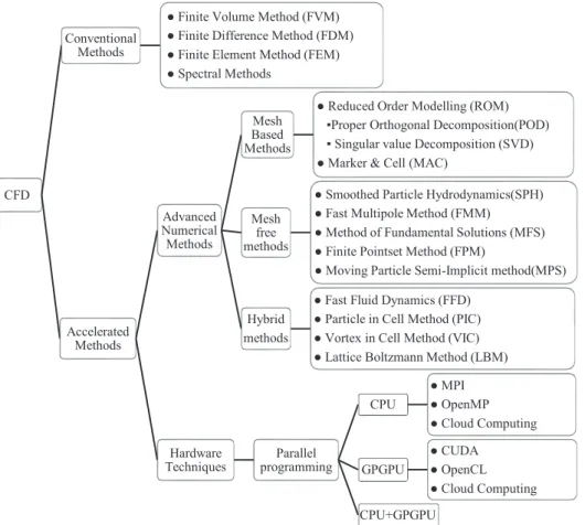
Figure 3.1: Hierarchical classification of methods in CFD
Mesh-free particle methods on the other hand have several advantages over the mesh based methods. For example, the mass is automatically balanced and therefore there is no need to solve the mass transport equation (4.1) in the Navier Stokes equations. Moreover, the nonlinear convective term in the mo-mentum transport equation (4.2) is no longer needed as the convection of the particles will occur automatically due to the interaction forces among the par-ticles in the system. Furthermore, for free surface flow like the impinging jet problem, there is no need to solve the two phases (air-water) to identify the interface between them. The surface tension of the water itself will create the
CFD
Conventional Methods
● Finite Volume Method (FVM) ● Finite Difference Method (FDM) ● Finite Element Method (FEM) ● Spectral Methods Accelerated Methods Advanced Numerical Methods Mesh Based Methods
● Reduced Order Modelling (ROM) ▪Proper Orthogonal Decomposition(POD) ▪ Singular value Decomposition (SVD) ● Marker & Cell (MAC)
Mesh free methods
● Smoothed Particle Hydrodynamics(SPH) ● Fast Multipole Method (FMM) ● Method of Fundamental Solutions (MFS) ● Finite Pointset Method (FPM)
● Moving Particle Semi-Implicit method(MPS) Hybrid
methods
● Fast Fluid Dynamics (FFD) ● Particle in Cell Method (PIC) ● Vortex in Cell Method (VIC) ● Lattice Boltzmann Method (LBM)
Hardware
Techniques programmingParallel
CPU ● MPI ● OpenMP ● Cloud Computing GPGPU ● CUDA ● OpenCL ● Cloud Computing CPU+GPGPU
10
air-water interface. Consequently, this type of method has been used to simu-late large scale problems in real time, for example, SPH in Auer (2008) and Krog and Elster (2012) and Fast Multipole Method (FMM) in Yokota et al.(2013). However, these methods are still under development and not suffi-ciently mature for all type of process simulation problems.
Hybrid methods are also of interest for free surface flows, multiphase flows and heat transfer simulations. In recent developments, researchers have been trying to combine different methods to develop new methods that combine benefits from both Eulerian and Lagrangian frames of reference. An example of these is Fast Fluid Dynamics (FFD), as used by Zuo and Chen (2010, 2009) to simulate air flow inside buildings in real time. Another method, LBM, solves the Boltzmann equation instead of the Navier Stokes equations and is quite popular for thermal problems. Geveler et al.(2011) implemented LBM to solve various complex fluid flow cases, achieving real-time performance.
This literature review demonstrates that the difficulties and challenges of simulating industrial flow and heat transfer in real time have not been ade-quately discussed in the literature. The literature review of real-time simula-tions also indicates that most of the advanced accelerated methods presented in Figure 3.1 are still under development and are not well adapted for all types of fluid flow problems. However, among these methods, SPH and LBM seem to be popular in the CFD community due to their promising performance and suitability for the applications of the current research topic.
In this thesis, traditional mesh based solvers are used to analyse flow and heat transfer for industrial processes while using the acceleration techniques from HPC. The models and results from the simulations are presented and the difficulties and challenges in simulating industrial processes are discussed. The SPH method is currently being adapted and employed to solve industrial flow problems. Some interesting results have been achieved, however these latest results are not included in this thesis because they have not yet been analysed and validated. The thermal modelling equations for simulating heat transfer for industrial processes are yet to be implemented in the SPH solver. In future, comparisons between SPH and LBM as well as comparison with the traditional mesh based solvers will be presented from the real-time simulation perspective to provide additional insight into the usage of these methods for industrial processes. The ultimate goal of this thesis is to direct our research work towards real-time simulations for industrial processes. The target is to use the results from the real-time simulations in an online control tool for de-cision support and to operate the processes in an energy efficient way.
11
4 Methodology
This chapter briefly describes the different methodologies used in this thesis. The theories and models used to perform the simulations are also presented here.
4.1 Industrial process
The process illustrated in Figure 4.1 is a very long process in hot rolling steel industries, where the steel slabs are rolled into thin sheets. The first step of this process is to heat the steel slabs up to 1250°C in the furnace where Pro-pane (Liquefied Petroleum Gas (LPG)) is used as fuel for the combustion. The second step is to roll the heated slab mechanically with large rollers in several stages. The final step is to cool the sheets down to 200°C at the Runout Table (ROT), where hundreds of water jets impinge on the steel sheet to cool it rap-idly. In this thesis, the focus is on the first step, the furnace (Paper II), and the last step, the Runout table cooling (Paper I), of the hot rolling process.
12
4.2 Modelling
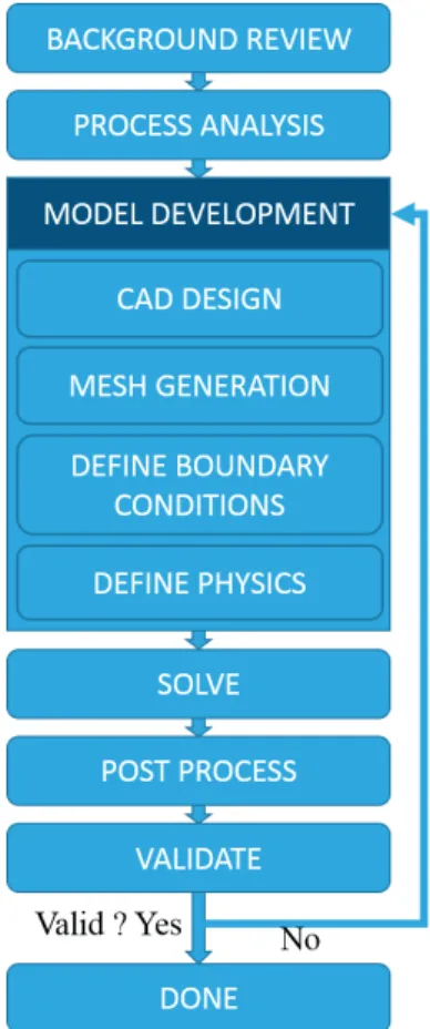
Once an industrial process is selected for analysis using CFD simulations, a background review is performed to understand the research field and to gather information on related work published by other researchers before proceeding. The process is then analysed to generate sufficient information to be able to build the numerical domain and select the most realistic boundary conditions. The numerical domain is then discretised using different types of mesh cells and mathematical models are employed to solve the well-defined problems. After obtaining the first solution, mesh sensitivity analysis is performed to verify the mesh independency before accepting it as a final solution. Finally, post processing is done to visualise the results, and the data from the simula-tion is validated. All of the CFD simulasimula-tions presented in this thesis follow this methodology, see Figure 4.2.
Figure 4.2: Methodological approach for CFD simulations
The following sections present the models, i.e. the numerical domains together with the mesh and the mathematical model equations that are used to solve the problems.
13
4.2.1 Numerical model development techniques
The numerical model development techniques used in this thesis are discussed in this section.
4.2.1.1 Jet Cooling Problem
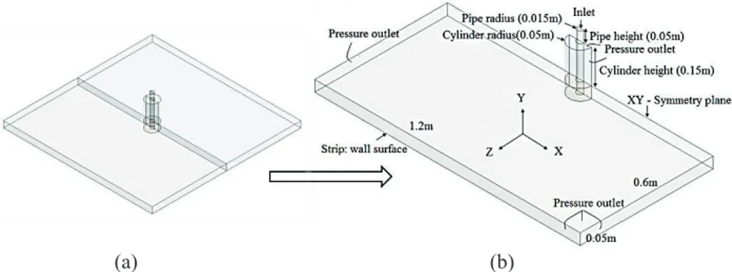
The ROT cooling process is in essence a jet impingement cooling case. At the ROT, the water jets hit the steel surface perpendicularly and then spread over the whole plate as a very thin liquid film. The liquid film height can be as small as one millimetre. Therefore, it is crucial to maintain at least few layers of cells in the mesh to resolve the liquid film layer and to be able to calculate the heat transfer coefficient from the temperature gradient across the cell lay-ers. Three different models are constructed in Paper I to analyse the heat trans-fer at the ROT. A 2D axisymmetric model, as presented in Figure 4.7a, is used to simulate a single water jet to study the heat transfer at the ROT and to in-vestigate the influence of the water flow rate on the heat transfer by perform-ing a parametric analysis. In addition, a 3D sperform-ingle jet as shown in Figure 4.3 is modelled to calculate the heat transfer and determine all the 3D hydrody-namic effects of the impinging jet. The two-jet case, as illustrated in Figure 4.4, is simulated in order to analyse jet-jet interaction and its influence on the heat transfer.
Typically, the ROT cooling section in a real hot rolling steel mill consists of hundreds of water jets, as illustrated in Figure 4.1, hitting the steel surface to generate uniform cooling over the whole steel plate. However, simulating a large number of jets using the methodology presented in Figure 4.2 is im-possible due to the need for a very large mesh to cover the whole ROT. The cooling effect from each water jet can be considered identical; however, there are significant interactions between the jets since they are so close to each other. Therefore, it is very important to know the impact of the interactions between the jets on the heat transfer in order to model the overall cooling ef-fect at the ROT accurately. Thus, models have been developed to analyse the cooling effect by a single water jet and a pair of jets to determine the jet-jet interaction effects (Paper I).
The numerical domain is created in such a way that the domain size is small enough to reduce the number of mesh cells but large enough to avoid possible influences of boundary conditions on the solution. In the ROT the water pipe nozzles are placed 200mm above the steel sheet. Therefore, the numerical do-main for the impinging jet consists of a circular beam of height 150mm con-necting the water pipe nozzle and a rectangular prism of height 50mm on the steel sheet, see Figure 4.3 and Figure 4.4. The circular beam diameter is cho-sen so that the interface between air and water is not affected by the pressure outlet boundary condition. For the single jet model, symmetry boundary con-dition is applied on one side, thus only half of the domain is modelled, as
14
demonstrated in Figure 4.3b. For the two jet case, symmetry boundary condi-tion is applied on two sides, thus only a quarter of the original domain is mod-elled, as presented in Figure 4.4b.
(a) (b)
Figure 4.3: Single jet case in 3D. (a) Full 3D domain (b) 3D model with dimensions and boundary conditions
(a) (b)
Figure 4.4: Two-jet case in 3D (a) full 3D domain and (b) 3D model with dimensions and boundary conditions
Figure 4.5: Whole furnace (side view) in 2D showing different zones, burners and thermocouples (TC) in Zone1
15 Figure 4.6: Numerical domain with boundary conditions (BC) (a) Burner
configu-ration in 3D (b) Numerical domain with single burner (c) Zone 1 and 2 in 3D (d) Burner configuration in 2D
4.2.1.2 Furnace
The furnace at the studied hot rolling steel mill consists of 8 zones in total, where Zone 1 and Zone 2 are the preheating zones, see Figure 4.5. Zone 1 has 8 burners in a row, each with approximately 3500KW capacity, see Figure 4.6c. The burners in Zone 1 are configured in a periodic manner. Therefore, there is a single burner in the middle, as illustrated in Figure 4.6a and d, with all the real dimensions together with a long slice of Zone 1, as shown in Figure 4.6b. This is modelled at full scale in Paper II. Periodic boundary conditions are used on both sides of the cross section surfaces of the numerical domain to represent the whole of Zone 1, see Figure 4.6b. Zone 2 has a similar power capacity to Zone 1. Therefore, we consider Zone 2 to be identical to Zone 1 and we use symmetry boundary condition to represent Zone 2, see Figure 4.6b. In this way, the numerical domain is greatly reduced in comparison to the original size of Zone 1 and Zone 2, but still represents them numerically.
4.2.2 Meshing techniques
4.2.2.1 Jet Cooling Problem
The mesh for the impinging jet cooling problem is generated using only rec-tangular cells for the 2D case and hexahedral cells for the 3D case, see Figure 4.7. Impinging water jet is a multiphase flow problem and it is not known where the interface between the air and water will be. Therefore, the mesh is
16
refined in the vicinity where the interface is expected since capturing the in-terface accurately is very important for obtaining a realistic flow pattern for the water jet. Moreover, the cells close to the steel sheet are refined to maintain a y+ value around 30. A y+ value in this range guarantees the turbulence wall law functionality (Salim and Cheah, 2009).
(a) (b)
Figure 4.7: Mesh for impinging jet cooling model (a) 2D-axisymmetric model (b) 3D model
4.2.2.2 Furnace
Figure 4.8a and b present the mesh for the furnace. Refined cells are used to capture all the small scale effects of the burners, combustion and the heat transfer to the steel slab. The y+ value is maintained at 30 at the steel slab surface which is sufficient to ensure the turbulence wall law functionality (Salim and Cheah, 2009).
Figure 4.8: Mesh for the numerical domain (3.4 million cells) (a) burner (b) the whole domain
17 Table 2: Mesh information for all the models
Model Number of cells (approx.)
Cell
type aspect Max ratio Min orthogonal quality Max Skew-ness Y+ value at wall 2D-axisymmetric
(ROT) thousand 27 Quad 37 1 None 2~15
3D 1-jet (ROT) 1.4
million Hex 44 0.74 0.55 4~30
3D 2-jet (ROT) 1.6
mil-lion Hex 51 0.70 0.57 4~33
Furnace 3.4
mil-lion Mixed 34 0.23 0.85 30~300
4.2.3 Mathematical models
The computational transport equation systems employed to model the Runout Table (ROT) cooling in Paper I are (4.1) – (4.4) and (4.6) – (4.12).The transport equations system used to model the combustion and the heat transfer in Paper II are (4.1) – (4.9).
4.2.3.1 Mass and momentum transport equation
The equation for mass conservation employed in the model is:
𝜕𝜕
𝜕𝜕𝑥𝑥𝑖𝑖(𝜌𝜌𝑢𝑢𝑖𝑖) = 0 (4.1)
Conservation of momentum equation can be written as follows:
𝜕𝜕 𝜕𝜕𝑥𝑥𝑗𝑗(𝜌𝜌𝑢𝑢𝑖𝑖𝑢𝑢𝑗𝑗) = − 𝜕𝜕𝜕𝜕 𝜕𝜕𝑥𝑥𝑖𝑖+ 𝜕𝜕 𝜕𝜕𝑥𝑥𝑗𝑗𝜏𝜏𝑖𝑖𝑗𝑗+ 𝜕𝜕 𝜕𝜕𝑥𝑥𝑗𝑗(−𝜌𝜌𝑢𝑢𝑖𝑖 ′𝑢𝑢 𝑗𝑗′ ̅̅̅̅̅̅) (4.2)
Where the Newtonian fluid stress tensor,
𝜏𝜏𝑖𝑖𝑗𝑗 = (𝜇𝜇 + 𝜇𝜇𝑡𝑡) (𝜕𝜕𝑢𝑢𝜕𝜕𝑥𝑥𝑗𝑗𝑖𝑖+𝜕𝜕𝑢𝑢𝜕𝜕𝑥𝑥𝑗𝑗𝑖𝑖−23𝜕𝜕𝑢𝑢𝜕𝜕𝑥𝑥𝑘𝑘𝑘𝑘𝛿𝛿𝑖𝑖𝑗𝑗) (4.3)
The Reynolds stress term (−𝜌𝜌𝑢𝑢̅̅̅̅̅̅) is defined as 𝑖𝑖′𝑢𝑢𝑗𝑗′
−𝜌𝜌𝑢𝑢̅̅̅̅̅̅ = 𝜇𝜇𝑖𝑖′𝑢𝑢𝑗𝑗′ 𝑡𝑡(𝜕𝜕𝑢𝑢𝜕𝜕𝑥𝑥𝑗𝑗𝑖𝑖+𝜕𝜕𝑢𝑢𝜕𝜕𝑥𝑥𝑗𝑗𝑖𝑖) −23(𝜌𝜌𝜌𝜌 + 𝜇𝜇𝑡𝑡𝜕𝜕𝑢𝑢𝜕𝜕𝑥𝑥𝑘𝑘𝑘𝑘) 𝛿𝛿𝑖𝑖𝑗𝑗 (4.4)
4.2.3.2 Mixture fraction transport equation
The mixture fraction concept is applied under the assumption of equal mass diffusivities of the species involved in the system. The individual species transport equation is then reduced to a single transport equation for the mixture fraction 𝑓𝑓 = 𝑍𝑍𝑖𝑖−𝑍𝑍𝑖𝑖,𝑜𝑜𝑜𝑜
18
𝛻𝛻. (𝜌𝜌𝑣𝑣⃗𝑓𝑓) = 𝛻𝛻. (𝜇𝜇+𝜇𝜇𝑡𝑡
𝜎𝜎𝑡𝑡 𝛻𝛻𝑓𝑓) + 𝑆𝑆𝑚𝑚+ 𝑆𝑆𝑢𝑢𝑢𝑢𝑢𝑢𝑢𝑢 (4.5)
Where, 𝜇𝜇 and 𝜇𝜇𝑡𝑡 are laminar and turbulent viscosity respectively. 𝜎𝜎𝑡𝑡 is a
con-stant with value 0.85.
4.2.3.3 Energy transport equation
The energy transport equation used together with the mass and momentum transport equation can be stated as follows:
𝜕𝜕 𝜕𝜕𝑥𝑥𝑖𝑖[𝑢𝑢𝑖𝑖(𝜌𝜌𝜌𝜌 + 𝑝𝑝)] = 𝜕𝜕 𝜕𝜕𝑥𝑥𝑗𝑗(𝐾𝐾𝑢𝑢𝑒𝑒𝑒𝑒 𝜕𝜕𝜕𝜕 𝜕𝜕𝑥𝑥𝑗𝑗+ 𝑢𝑢𝑖𝑖(𝜏𝜏𝑖𝑖𝑖𝑖)𝑢𝑢𝑒𝑒𝑒𝑒) + 𝑆𝑆ℎ (4.6)
Where E is the total energy, 𝐾𝐾𝑢𝑢𝑒𝑒𝑒𝑒= 𝐾𝐾 + 𝐶𝐶𝑝𝑝 𝜇𝜇𝑡𝑡/𝑃𝑃𝑟𝑟𝑡𝑡 is the effective thermal
conductivity, 𝑆𝑆ℎ is heat of the chemical reaction and (𝜏𝜏𝑖𝑖𝑖𝑖)𝑢𝑢𝑒𝑒𝑒𝑒 is the deviatoric
stress tensor, defined as
(𝜏𝜏𝑖𝑖𝑖𝑖)𝑢𝑢𝑒𝑒𝑒𝑒 = 𝜇𝜇𝑢𝑢𝑒𝑒𝑒𝑒(𝜕𝜕𝑢𝑢𝜕𝜕𝑥𝑥𝑗𝑗𝑖𝑖+𝜕𝜕𝑢𝑢𝜕𝜕𝑥𝑥𝑗𝑗𝑖𝑖) −23𝜇𝜇𝑢𝑢𝑒𝑒𝑒𝑒𝜕𝜕𝑢𝑢𝜕𝜕𝑥𝑥𝑘𝑘𝑘𝑘𝛿𝛿𝑖𝑖𝑖𝑖 (4.7)
4.2.3.4 Turbulence model equations
Industrial flow problems are most often turbulent and thus require the turbu-lence to be modelled numerically. There are several turbuturbu-lence models avail-able in the open literature. Among them, the 𝑘𝑘 − 𝜀𝜀 model is the most popular and economical turbulence model for industrial processes. The Realizable k-ε turbulence model is therefore used for the simulations presented in this thesis. The equations describing the turbulence kinetic energy (𝑘𝑘) and the turbulence dissipation rate (𝜀𝜀) are as follows:
𝜕𝜕 𝜕𝜕𝑥𝑥𝑗𝑗(𝜌𝜌𝑘𝑘𝑢𝑢𝑖𝑖) = 𝜕𝜕 𝜕𝜕𝑥𝑥𝑗𝑗[(𝜇𝜇 + 𝜇𝜇𝑡𝑡 𝜎𝜎𝑘𝑘) 𝜕𝜕𝜕𝜕 𝜕𝜕𝑥𝑥𝑗𝑗] + 𝐺𝐺𝜕𝜕− 𝜌𝜌𝜀𝜀 − 𝑌𝑌𝑀𝑀 (4.8) 𝜕𝜕 𝜕𝜕𝑥𝑥𝑗𝑗(𝜌𝜌𝜀𝜀𝑢𝑢𝑖𝑖) = 𝜕𝜕 𝜕𝜕𝑥𝑥𝑗𝑗[(𝜇𝜇 + 𝜇𝜇𝑡𝑡 𝜎𝜎𝜀𝜀) 𝜕𝜕𝜕𝜕 𝜕𝜕𝑥𝑥𝑗𝑗] + 𝜌𝜌𝐶𝐶1𝑆𝑆𝜀𝜀 − 𝜌𝜌𝐶𝐶2 𝜕𝜕2 𝜕𝜕+√𝜈𝜈𝜕𝜕 (4.9)
Where turbulence viscosity 𝜇𝜇𝑡𝑡 = 𝜌𝜌𝐶𝐶𝜇𝜇𝜕𝜕
2 𝜕𝜕, 𝐶𝐶1= 𝑚𝑚𝑚𝑚𝑚𝑚 [0.43, 𝑘𝑘 𝜀𝜀√2𝑆𝑆𝑖𝑖𝑗𝑗𝑆𝑆𝑖𝑖𝑗𝑗 𝑘𝑘 𝜀𝜀√2𝑆𝑆𝑖𝑖𝑗𝑗𝑆𝑆𝑖𝑖𝑗𝑗+5 ],𝐶𝐶2= 1.9, 𝜎𝜎𝜕𝜕 = 1.0 and 𝜎𝜎𝜕𝜕 = 1.2
4.2.3.5 Heat transfer coefficient
The convective heat transfer coefficient is calculated from the heat flux 𝑞𝑞′′ at the wall surface by
𝑞𝑞′′= ℎ(𝑇𝑇
19 The local surface heat flux can be obtained by using the Fourier law of heat conduction at the boundary layer by
𝑞𝑞′′= −𝐾𝐾 𝑓𝑓𝜕𝜕𝜕𝜕𝜕𝜕𝜕𝜕|
𝜕𝜕=0 (4.11)
The Nusselt number 𝑁𝑁𝑢𝑢𝑑𝑑 based on the diameter of the nozzle is calculated
from the heat transfer coefficient ℎ using
20
5 Results and discussion
This chapter presents and discusses the important results from the appended papers. The CFD simulation results from Paper I and Paper II are presented to discuss the accuracy and reliability of the commercial CFD solvers by solving two problems: (I) the heating of the steel slabs by combustion in the furnace (Paper II), and (II) the cooling of steel sheet at the ROT (Paper I). These are the first and the last steps respectively of the hot rolling process in steel indus-tries, see Figure 4.1. The merits and demerits of most commonly used methods to solve CFD problems are discussed, and alternative methods have been pro-posed based on the literature review presented in Paper III.
5.1 Results
5.1.1 The jet-cooling problem
The impinging water jet is a free surface flow where the interface between air and water is of special interest. Obtaining the right flow is key to calculating the correct heat transfer. We verify the results in terms of interface, liquid film height and the Nusselt number (non-dimensional heat transfer coefficient) us-ing theory and data published in the literature.
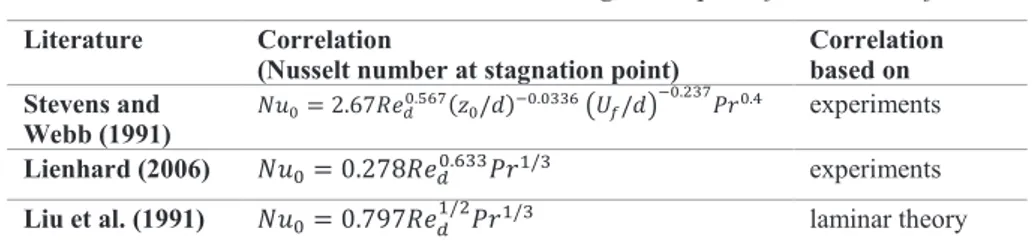
Table 3: Nusselt number correlation at stagnation point for turbulent jets Literature Correlation
(Nusselt number at stagnation point) Correlation based on Stevens and
Webb (1991) 𝑁𝑁𝑢𝑢0= 2.67𝑅𝑅𝑒𝑒𝑑𝑑
0.567(𝑧𝑧
0/𝑑𝑑)−0.0336 (𝑈𝑈𝑓𝑓/𝑑𝑑)−0.237𝑃𝑃𝑃𝑃0.4 experiments
Lienhard (2006) 𝑁𝑁𝑢𝑢0= 0.278𝑅𝑅𝑒𝑒𝑑𝑑0.633𝑃𝑃𝑃𝑃1/3 experiments
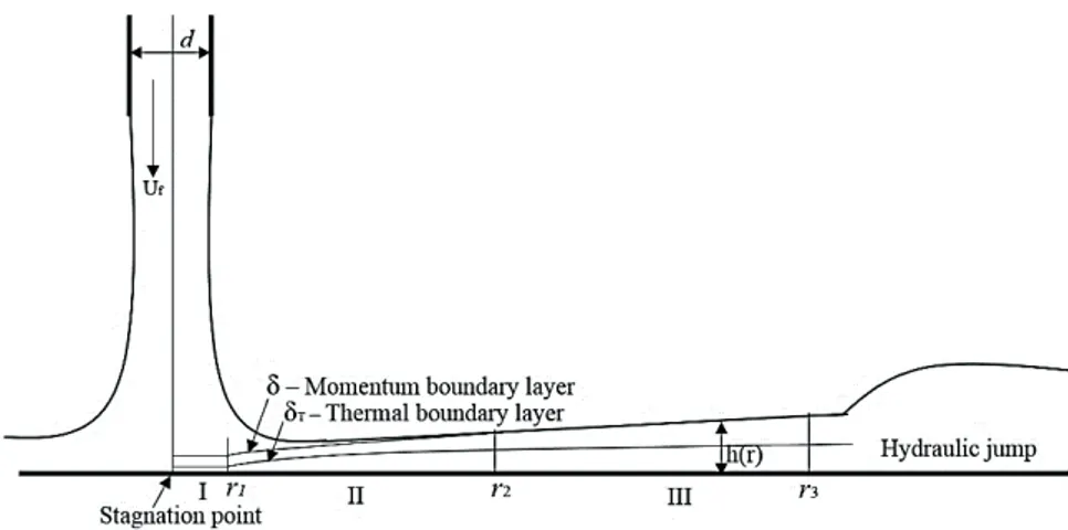
21 Figure 5.1: Impinging jet, I: the stagnation zone, II: the laminar boundary
layer, III: the momentum boundary layer reaches the film surface
Figure 5.2: Interface of the water jet for different inlet velocities
The inlet velocity and the gravitational effect on the interface of the water jet can be described using the continuity equation and the Bernoulli equation as follows:
22
Where, D is the nozzle diameter, d is jet diameter, 𝑈𝑈𝑓𝑓 is the fluid velocity at
inlet, Z is distance downward from the nozzle and 𝑧𝑧0 is the distance between
the nozzle and the strip. The derivation of equation (5.1) is presented in the Appendix of the thesis.
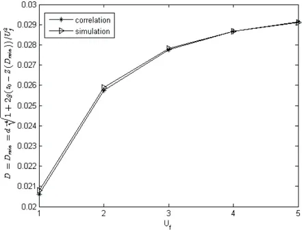
Figure 5.3: Comparison between simulation and correlation (4.1) of the minimum jet diameter (𝐷𝐷𝑚𝑚𝑚𝑚𝑚𝑚)
The captured interface from the simulation for five different flow rates is pre-sented in Figure 5.2 and verified using the correlation (5.1). The minimum jet diameter 𝐷𝐷𝑚𝑚𝑚𝑚𝑚𝑚 between the pipe nozzle and the steel sheet is in good
agree-ment with the correlation (5.1) for all the flow rates, see Figure 5.3.
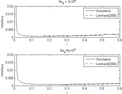
As mentioned previously, the water jet spreads over the whole surface as a very thin film after impingement. The height of this liquid film was studied in Lienhard (2006) and Liu et al.(1991), and the following correlation was pre-sented:
ℎ(𝑟𝑟) = 0.1713 𝑑𝑑2/𝑟𝑟 + 5.147 𝑟𝑟2/(𝑅𝑅𝑒𝑒
𝑑𝑑𝑑𝑑) (5.2)
The liquid film height on the steel surface is in agreement with the correlation (5.2) presented in Lienhard (2006) and Liu et al.(1991), see Figure 5.4. Over-all, the flow pattern of the impinging jet is simulated successfully. The Nusselt number for the stagnation point from the simulation presented in Figure 5.5 found to be in the same range as in the correlation established in Lienhard (2006), which is based on experimental data. However, the predicted Nusselt number based on laminar assumptions presented in Liu et al. (1991) are well
23 below the calculated Nusselt number from the simulations. This is because the turbulence has a large influence on the Nusselt number and the Nusselt num-ber for the turbulent jet is usually much higher compared to that of the laminar jet (Lienhard, 2006).
Figure 5.4: Comparison of film thickness with correlation (5.2)
24
Figure 5.6: Nusselt number comparison for single jet and two-jet case
(a) (b) Figure 5.7: Heat transfer performance (a) Total temperature field over the plate
in kelvin (K) for Single-jet (b) Total temperature field over the plate in kelvin (K) for Two-jet
Figure 5.7 presents the temperature contours for the single and two-jet cases. In the two-jet case, the jets are separated by 14 times the nozzle diameter and therefore the jet-jet interaction has almost no influence on the heat transfer, see Figure 5.6. However, the simulation shows that more uniform cooling is achieved by using two jets in comparison to the single jet case, as illustrated in Figure 5.7. The distance between jets needs to be reduced to increase the
25 jet-jet interaction effect on the heat transfer performance. However, it is very difficult to get a stable solution for the two-jet case due to the observed splash-ing of the water when the liquid films from the two jets interact with each other.
5.1.2 Furnace
In hot rolling steel mills, the steel slabs are heated in the furnace to 1250°C by propane combustion. The steel plants usually have their own recipe where they heat the slabs by following an ideal temperature curve to maintain a desired steel sheet quality. In reality, only a few thermocouples (Type S) are placed inside the furnace to measure the gas temperature, as shown in Figure 4.5. These are then used to estimate the slab surface temperature and the average temperature of the steel slab in order to follow the ideal curve. At the steel mill, the measured gas temperatures from the thermocouples are interpolated to generate a continuous temperature profile for the gas and the estimated slab surface, which is then compared with the ideal curve. There are no direct measurements on the slab surface. The flow and the complex combustion in-side the furnace are highly turbulent. Flow mixing and recirculation are seen inside the furnace, as can be seen in Figure 5.8, which drive the combustion and the heat transfer pattern. The average gas temperature from the simulation is compared with the measured gas temperature from the thermocouples at the same location during the furnace operation in Table 4. The calculated gas tem-perature is in overall good agreement with the measured gas temtem-perature (Ta-ble 4), however, the simulated temperature of the steel slab surface deviates from the interpolated data from the measurements in the real plant to follow the ideal curve during the furnace operation, see Figure 5.9. A similar pattern was observed in the investigation by Morgado et al. (2015).
Figure 5.8: Path lines of the velocity (ms-1) on the cross section plane in the middle of the domain showing the recirculation
26
Figure 5.9: Surface temperature of the steel slab
Table 4. Comparison between average temperature of thermocouples and simulation
Average data
TC 1 & 2 (°C) TC 3 & 4 (°C) Average data TC 5 & 6 (°C) Average data Measurement 830 ± 2% 880 ± 2% 1320 ± 2%
Simulation 877 860 1310
Relative error 5.66% 2.27% 0.75%
5.2 Further remarks
The results presented in section 5.1.1 and section 5.1.2 provide information about the accuracy level when using the traditional mesh based CFD methods implemented in the commercial packages. Table 5 shows the approximate runtime to achieve a converged solution for the models used in this thesis. The results indicate that it is not possible to simulate even a small part of an indus-trial process in real time with the methods and models used here. However, these methods are suitable if accuracy is the main concern. Some of the ad-vanced methods presented in Figure 3.1 are being used successfully in the respective user communities in real time as explained in chapter 3, however the accuracy of the solutions is not always validated. Nevertheless, the
accu-27 racy obtained by the accelerated CFD methods is still acceptable for large in-dustrial processes and can be used in online tools to examine the impact of various parameters which are often useful for decision support.
Table 5: CPU time for a converged solution Model RANS Solver Number
of CPUs Mesh size Approximate Run time (Real clock) ROT- 2D
Axisymmetric Pseudo transient 16 27 thousand ~ 5 hours ROT - 3D(1 -jet) Steady state 32 1.4 million ~ 24 hours
ROT - 3D(2 -jet) Steady state 32 1.6 million ~ 30 hours
Furnace Steady state 64 3.4 million ~ 48 hours
Based on the author’s experience gathered during the investigation described in this thesis, the results presented herein, in the appended papers and from the literature review, the following can be summarised:
Difficulty and challenges: Mesh based CFD solvers
o Meshing is cumbersome for complex geometries
o Need to ensure the quality of the mesh before accepting a final solu-tion
o Boundary layer needs to be refined properly in order to be able to calculate the heat transfer accurately
o Need to ensure that the solution is mesh independent (mesh sensitivity analysis)
o Need to guess where the local refinement should be done based on the flow problem during meshing
Mesh-free CFD solvers
o Satisfying the boundary condition for flow with high velocity o Variable size particles for small features make the algorithms
compli-cated
28
Limitations:
Mesh based CFD solvers
o Significantly longer time required during meshing compared to the simulation time
o Large number of cells due to local refinements and to maintain a rea-sonable growth rate of the cell size
o Require moving mesh to represent solid movements => Longer runtime, stability issues
o Smaller cell size requires smaller time steps for the transient simula-tions
o Stability issues during fluid-fluid interactions at high speed Mesh-free CFD solvers
o No available implementation for combustion or chemical engineering o Not sufficiently mature for industrial applications
29
6 Conclusions
The main focus in this thesis is simulation of different industrial processes using commercial CFD packages, to validate the results and to direct subse-quent research on accelerated CFD simulations for fluid flow and heat trans-fer.
The core focus of the research work is to run CFD simulations for industrial processes in real time and use the results in the online control system for op-timal control, decision support and diagnostics. The current approach towards accelerating the CFD simulation is to use HPC resources to solve the CFD problems using the mesh based methods available in the commercial CFD solvers.
The results presented in this thesis provide information about the complex-ity of modelling industrial flow and heat transfer processes. The simulation of the cooling problem at the ROT was possible by limiting the simulation do-main using all possible choices such as symmetry and periodicity. The results show that there is a significant degree of interaction between the water jets which causes instabilities in the numerical solution and makes it difficult to solve the problems when several jets close to each other are operating simul-taneously. The simulation results for the heating process of the slab in the furnace through combustion show very complex flow mixing with high de-grees of recirculation, which makes it difficult to converge to a solution. To solve the complex flow and heat transfer associated with the hot rolling indus-tries using mesh based methods, one needs a refined mesh to resolve all the flow interactions and recirculation. This requirement for locally refined mesh is a serious limitation for the mesh based solvers to use this method for real-time numerical simulations, even though multicore supercomputers are usu-ally used to run the solvers using parallel computing.
Mesh based CFD simulations for large industrial processes e.g. ROT and industrial furnace cannot be used for online applications due to their large CPU time requirement. This simulation time is justified by considering all the physical scales present in a complex engineering process. Multiple space and time scales illustrate a strong interaction between the physical phenomena. This must be properly taken into account in CFD simulation which always requires a large simulation time. The performance of the solver used in this thesis indicates the limitations of mesh based solvers and suggests that alter-native methods must be identified to be able to reach the goal of real-time simulation. There is always a balance to be achieved between speed and the
30
accuracy of the simulation. One may achieve very fast simulation using a very coarse mesh, but the accuracy will be questionable as the solver may fail to capture the detail of the flow mixing and interesting features due to the unre-solved mesh. There is a saying about mesh based solvers that “The solution is never better than the mesh”, since accuracy is directly related to the mesh res-olution. The results presented in this thesis show that, acceleration techniques from HPC alone will not allow real-time simulation when simulating the whole process in detail.
The literature review (Paper III) suggests alternative methods for speeding up simulations from the mathematical point of view. We propose to use these advanced fast CFD methods together with the HPC resources to bring the sim-ulation online. To this end, I have reviewed all the available CFD methods and listed and discussed the most popular and likely methods for speeding up the CFD simulations to guide subsequent steps towards the goal of real-time sim-ulations for online control.
31
7 Future work
The literature review is directed towards accelerated CFD simulations for fluid flow and heat transfer of large industrial processes. Based on the literature, two methods (from the list in Figure 3.1), namely Smoothed Particle Hydro-dynamics (SPH) and Lattice Boltzmann Method (LBM) have been identified as suitable methods for the current research topic. The SPH method is already employed to simulate the Runout table cooling process using the open source code dualSPHysics in GPGPU. The solver is currently only able to simulate the fluid flow with multiple water jets impinging on a moving surface, where promising computational performance is achieved. However, this thesis does not include the results from the ROT simulations using SPH, as it requires additional flow analysis and validation before the results can be presented to the scientific community. In the next step, the thermal equations will be im-plemented into the open source code dualSPHysics to be able to simulate the heat transfer. Based on the computational performance of the current SPH solver, it is likely that this work will lead to real-time or near real-time simu-lation for the industrial process in the near future.
The SPH and LBM methods still need to be evaluated for industrial process simulations. The results from SPH and LBM solvers will be compared with the results from the mesh based solvers implemented in the commercial CFD packages in terms of accuracy and speed to inform the progress towards real-time simulations.
32
References
Auer, S., 2008. Realtime particle-based fluid simulation, Master thesis, Technische Universität München, Germany.
Cho, M.J., Thomas, B.G., Lee, P.J., 2008. Three-Dimensional Numerical Study of Impinging Water Jets in Runout Table Cooling Processes. Metall. Mater. Trans. B 39, 593–602. doi:10.1007/s11663-008-9160-8
Dong, W., 2000. Design of advanced industrial furnaces using numerical modeling method.
Geveler, M., Ribbrock, D., Mallach, S., Göddeke, D., 2011. A simulation suite for Lattice-Boltzmann based real-time CFD applications exploiting multi-level parallelism on modern multi- and many-core architectures. J. Comput. Sci. 2, 113–123. doi:10.1016/j.jocs.2011.01.008
Hosain, M.L., Bel Fdhila, R., Daneryd, A., 2015. Heat transfer by liquid jets impinging on a hot flat surface. Appl. Energy 164, 934–943. doi:10.1016/ j.apenergy.2015.08.038
Hosain, M.L., Bel Fdhila, R., Sand, U., Engdahl, J., Dahlquist, E., Li, H., 2016. CFD Modeling of Real Scale Slab Reheating Furnace, in: 12th International Conference on Heat Transfer, Fluid Mechanics and Thermodynamics, HEFAT2016.
Hosain, M.L., Fdhila, R.B., 2015. Literature Review of Accelerated CFD Simulation Methods towards Online Application. Energy Procedia 75, 3307–3314. doi:10.1016/j.egypro.2015.07.714
Huang, M.-J., Hsieh, C.-T., Lee, S.-T., Wang, C.-H., 2008. A Coupled Numerical Study of Slab Temperature and Gas Temperature in the Walking-Beam-Type Slab Reheating Furnace. Numer. Heat Transf. Part A Appl. 54, 625–646. doi:10.1080/10407780802289475
Kim, J.G., Huh, K.Y., Kim, I.T., 2000. Three-Dimensional Analysis of the Walking-Beam-Type Slab Reheating Furnace in Hot Strip Mills. Numer. Heat Transf. Part A Appl. 38, 589–609. doi:10.1080/104077800750021152
Krog, Ø.E., Elster, A.C., 2012. Fast GPU-Based Fluid Simulations Using SPH. pp. 98–109. doi:10.1007/978-3-642-28145-7_10
Lappo, V., Habashi, W., 2009. Reduced order pod/kriging modeling for real-time 3d cfd. 11th Pan-American Congr. Appl. Mech. January 04-08, 2010, Brazil. Li, Y., Zhu, L., 2014. Cost of energy saving and CO2 emissions reduction in China’s
iron and steel sector. Appl. Energy 130, 603–616. doi:10.1016/j.apenergy.2014.04.014
33 Liao, Q., Jen, T., 2011. Application of Lattice Boltzmann Method in Fluid Flow and
Heat Transfer. World Scientific Publishing Company.
Lienhard, J.H., 2006. Impingement cooling with free-surface liquid jets. 18th Natl. 7th ISHMT-ASME Heat Mass Transf. Conf.
Lieu, T., Farhat, C., Lesoinne, M., 2006. Reduced-order fluid/structure modeling of a complete aircraft configuration. Comput. Methods Appl. Mech. Eng. 195, 5730– 5742. doi:10.1016/j.cma.2005.08.026
Liu, X., Lienhard, J.H., Lombara, J.S., 1991. Convective Heat Transfer by Impingement of Circular Liquid Jets. J. Heat Transfer 113, 571. doi:10.1115/1.2910604
Marino, P., Pignotti, A., Solís, D., 2002. Numerical model of steel slab reheating in pusher furnaces. Lat. Am. Appl. Res. 32, 257–261.
Mazumder, S., Lu, J., 2013. Faster-Than-Real-Time Simulation of Lithium Ion Batteries with Full Spatial and Temporal Resolution. Int. J. Electrochem. 2013, 1–10. doi:10.1155/2013/268747
Mishra, P.C., Nayak, S.K., Pradhan, P., Ghosh, D.P., 2015. IMPINGEMENT COOLING OF HOT METAL STRIPS IN RUNOUT TABLE - A REVIEW. Interfacial Phenom. Heat Transf. 3, 117–137. doi:10.1615/Interfac PhenomHeatTransfer.2014010574
Morgado, T., Coelho, P.J., Talukdar, P., 2015. Assessment of uniform temperature assumption in zoning on the numerical simulation of a walking beam reheating furnace. Appl. Therm. Eng. 76, 496–508. doi:10.1016/j.applthermaleng .2014.11.054
Salim, S., Cheah, S., 2009. Wall Y strategy for dealing with wall-bounded turbulent flows. Proc. Int. MultiConference.
Soon, Y., Ghazali, N., 2008. Numerical simulation of a microchip cooling with microjet array. J. Mek.
Stevens, J., Webb, B.W., 1991. Local Heat Transfer Coefficients Under an Axisymmetric, Single-Phase Liquid Jet. J. Heat Transfer 113, 71. doi:10.1115/ 1.2910554
Stopford, P.J., 2002. Recent applications of CFD modelling in the power generation and combustion industries. Appl. Math. Model. 26, 351–374. doi:10.1016/ S0307-904X(01)00066-X
Subramanyam, S., Crowe, K., 2000. Rapid design of heat sinks for electronic cooling using computational and experimental tools. Semicond. Therm. Meas. Manag. Symp. Sixt. Annu. IEEE.
Vakili, S., 2011. Analysis of water cooling process of steel strips on runout table. PhD Thesis, UBC.
Winder, D., 2004. Finite Element Analysis of Microchip Cooling. Thesis Proj. Univ. Tennessee - Knoxville.
Yokota, R., Barba, L.A., Narumi, T., Yasuoka, K., 2013. Petascale turbulence simulation using a highly parallel fast multipole method on GPUs. Comput. Phys. Commun. 184, 445–455. doi:10.1016/j.cpc.2012.09.011
34
Zhang, N., Lu, B., Wang, W., Li, J., 2010. 3D CFD simulation of hydrodynamics of a 150MWe circulating fluidized bed boiler. Chem. Eng. J. 162, 821–828. doi:10.1016/j.cej.2010.06.033
Zuo, W., Chen, Q., 2010. Fast and informative flow simulations in a building by using fast fluid dynamics model on graphics processing unit. Build. Environ. 45, 747– 757. doi:10.1016/j.buildenv.2009.08.008
Zuo, W., Chen, Q., 2009. Real-time or faster-than-real-time simulation of airflow in buildings. Indoor Air 19, 33–44. doi:10.1111/j.1600-0668.2008.00559.x