Supporting Usability in Product Line Architectures
Pia Stoll
Len Bass
Elspeth Golden, Bonnie E. John
Industrial Software
Systems
ABB Corporate Research
Västerås, Sweden
Software Engineering
Institute
Carnegie Mellon University
Pittsburgh, PA, USA
Human Computer Interaction
Institute
Carnegie Mellon University
Pittsburgh, PA, USA
pia.stoll@se.abb.com
ljb@sei.cmu.edu
egolden@cmu.edu, bej@cs.cmu.edu
Abstract
This paper addresses the problem of supporting usability in the early stages of a product line architecture design. The product line used as an example is intended to support a variety of different products each with a radically different user interface. The development cycles for new products varies between three years and five years and usability is valued as an important quality attribute for each product in the line.
Traditionally, usability is achieved in a product by designing according to specific usability guidelines, and then performing user tests. User interface design can be performed separately from software architecture design and prototyping, but user tests cannot be performed before detailed UI design and prototyping. If the user tests discover usability problems leading to required architectural changes, the company would not know about this until two years after the architecture design was complete. This problem was addressed by identifying a collection of 19 well known usability scenarios that require architectural support. In our example, the stakeholders for the product line prioritized three of these scenarios as key product-line scenarios for improving usability. For each of these three chosen product-line scenarios we developed an architectural responsibility pattern that provided support for the scenario. The responsibilities are expressed in terms of architectural requirements with implementation details and rationales. The responsibilities were embodied in a web based tool for the architects.
The two architects for the product line developed a preliminary design and then reviewed their design against the responsibilities supporting the scenarios. The process of review took a day and the architects conservatively estimated that it saved them five weeks of effort later in the project.
1. Introduction
ABB, a global leader in power and automation technologies, provides systems that enable utility and industry customers to improve their performance while
lowering environmental impact. To that end, ABB must design and implement extensive long-lived software systems. This paper presents the results of a collaboration between ABB Corporate Research, ABB core business units, and Carnegie Mellon’s Software Engineering Institute and Human-Computer Interaction Institute to support usability within the context of a product line architecture being newly developed.
The best method to support usability concerns through software architecture has been the subject of some investigation over the past years. In addition to the authors’ work [1,8,10], Folmer and his colleagues [6,7] and Juristo and her colleagues [11] have investigated the relationship between software architecture and usability. None of this work has gained widespread industrial acceptance primarily because all of the results reported require the hands-on involvement of the researchers. Our goal in the project reported on here was to deliver appropriate knowledge concerning usability and software architecture to ABB’s software architects in a format and at a time that would benefit their design, in a way that could scale to worldwide development efforts.
This paper reports the results of a new approach to providing usability knowledge to software architects early in the design process and without the active participation of the researchers. The activities reported on include
• Stakeholders selecting several usability scenarios important to the project under design
• The research team defining architectural patterns to satisfy the scenarios chosen
• The research team embedding those patterns into a tool • The architects using the tool for one day to review an
early version of their design. They did this without previous exposure to the patterns and without any participation by the research team.
• The architects reflecting on the impact of their use of the tool. They estimated that it saved them five weeks of work.
It was the next to last bullet – the architects using the knowledge embedded in the tool – that can be scaled. Since the tool is web based, architects in any project for which the usability scenarios embedded in the tool are relevant can use
the tool and the knowledge embedded in it without any involvement of the researchers involved.
2. Background
Prior to the collaboration reported in this paper, the project team in an ABB business unit developing a new product line of systems, together with an ABB research team, had done a use case analysis, performed a Quality Attribute Workshop to collect non-functional requirements from prioritized scenarios [3], used the Influencing Factors method [12] and conducted the first step of the Product Line Architecture development approach [5] with the identification of commonalities and variation points. Thus, from the requirements collection and analysis perspective, the project team was well prepared when they began to outline the architecture. The software architects had just starting sketching the architecture and had not yet written any code. Their implementation plan started with the backbone of the product line system, the core functionality, which would support all the variation points for the products. Usability had been prioritized as one of three most important software qualities for the new architecture during the Quality Attribute Workshop. One of the challenges for this project therefore was how to incorporate usability requirements into the core architecture early without having either a designed user interface or a finished prototype for user tests. The user interfaces are to be developed individually for each product and each product will use common core parts of the system. The product development cycles will vary between three and five years. Thus, the question was: How can we best support usability early when the product prototypes cannot be user tested until years after the architecture design is to be completed?
Most of standard usability evaluation techniques – questionnaires, heuristic evaluation, think-aloud usability studies – depend on having at least a paper prototype if not a running system. These types of tests may find modifications whose satisfaction requires changing the architecture. The effort of re-working the product-line architecture and the design for a line of products two years or even four years after the architecture has been established would be tremendous. The risk of finding severe usability problems requiring architectural work late in this development cycle was not acceptable and ABB decided to use usability-supporting architectural patterns (USAPs) in a collaboration with CMU. The decision was based on the fact that USAPs use generic usability scenarios common in complex systems and from these construct generic software architecture responsibilities. By working this way ABB expected to support some of the major usability issues early in the software design phase without having an actual user interface design in place.
A USAP is, as the name suggests, a software architectural pattern that provides instructions as to how to achieve specific usability scenarios. These patterns are at the
level of software architecture responsibilities. Examples of such patterns are canceling a long-running command, aggregating data, or supporting personalization of the user interface. Note that these are software architecture patterns in the flavor of [4] not usability patterns such as in [14]. Usability patterns describe user interface patterns such as an organization’s look and feel whereas software architecture patterns suggest software design solutions to specific problems.
As originally conceived, a USAP included six types of information. We illustrate the types with information from the cancellation USAP [10].
1. A brief scenario that describes the situation that the USAP is intended to solve. For example, “The user issues a command then changes his or her mind, wanting to stop the operation and return the software to its pre-operation state.”
2. A description of the conditions under which the USAP is relevant. For example, “A user is working in a system where the software has long-running commands, i.e., more than one second.”
3. A characterization of benefits to the user from
implementing the USAP. For example, “Cancel reduces the impact of routine user errors (slips) by allowing users to revoke accidental commands and return to their task faster than waiting for the erroneous command to complete.”
4. A description of the forces that impact the solution. For example, “No one can predict when the users will want to cancel commands”
5. An implementation-independent description of the solution, i.e., responsibilities of the software. For example, one implication of the force given above is the responsibility that “The software must always listen for the cancel command.”
6. A sample solution using UML-style diagrams. These diagrams were intended to be illustrative, not prescriptive, and were, by necessity, in terms of an overarching architectural pattern (e.g., MVC).
USAPs have been shown to significantly improve a software architecture design in laboratory experiments [8]. They have also been used in real development settings, with heavy involvement from the developers of the USAP [1]. However, these prior uses of USAPs suffer from two defects. First, the industrial usages have all involved the developers of USAPs. This clearly does not scale up. Secondly, the laboratory experiments were paper-based and the participants omitted important responsibilities of the USAPs, leaving additional room for quality improvement.
Our initial goals when we considered applying USAPs to the ABB project were to solve the two major problems that we have discussed.
1. The designers should be able to utilize the USAPs without immediate researcher involvement.
2. The designers should be encouraged to consider all of the responsibilities.
3. Prior work
Prior to working with ABB, the last three authors performed a laboratory experiment to test the utility of the various types of information in a USAP. The results also suggested directions for a delivery tool for USAPs, so summarizing the experiment and results here sets a context for the experience reported in this paper.
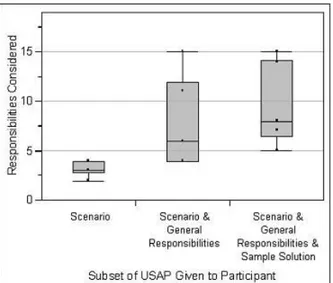
There were three different conditions in the experiment. Participants in the first condition were given only the scenario that describes the situation that the USAP is intended to solve. This mimics a common relationship between usability engineers and software designers in that the usability engineers provide general requirements (e.g., the system must be able to cancel long-running commands) but the creation of a design solution to fulfill those requirements is up to the software engineers.
Participants in the second condition were provided with the scenario plus a list of responsibilities that may have to be fulfilled to satisfy the scenario, depending on the particular system to which the scenario is being applied. Participants in the third condition were provided with the scenario, the list of responsibilities, and a sample solution using the MVC overarching architecture pattern, expressed in UML-style diagrams.
The results of the experiment were that providing the participants with information about responsibilities and a sample solution resulted in significantly better architecture design than those created by participants provided with just the scenario (p<0.05), but that the UML diagrams did not significantly improve the architecture design over the responsibilities alone. These results were reported in more detail in [8]. Figure 1 shows the results of the laboratory experiment.
Note, however, that there were 19 responsibilities in the
problem given to the participants in the laboratory study. Figure 1 shows that the group with the best performance achieved an average of only 9.5 responsibilities considered. That is, the participants’ solutions, on average, only addressed half of the responsibilities that might have been considered.
4. Stakeholder choice of scenarios
The initial interactions between the ABB project team and the CMU research team consisted of information exchange about the project being developed and about the USAP approach. The researchers then presented 19 usability scenarios possibly relevant to this domain.
• Progress feedback • Warning/status/alert feedback • Undo • Canceling commands • User profile • Help • Command aggregation • Action for multiple objects • Workflow model
• Different views of data • Keyboard shortcuts • Reuse of information
• Maintaining compatibility with other systems • Navigating within a single view
• Recovering from failure • Identity management • Comprehensive search • Supporting internationalization • Working at the user’s pace
The ABB project team was asked to prioritize the general usability scenarios and they decided to focus on two and add an additional one. The chosen scenarios were User Profile and Alarms and Events (renamed from Warning/status/alert feedback). The additional scenario was Environment Configuration.
5. USAP Patterns
In the process of developing the three USAPs that were tested by the architects, we developed a Pattern Language [2], consisting of foundational USAPs and end-user USAPs, to exploit the commonalities among the USAPs. The pattern language was not visible to the architect and we will not describe it in this paper. The interested reader is referred to [9] for a description of the pattern language.
There are two aspects of the patterns on which we will focus. First there is an enumeration of textual responsibilities. These responsibilities are implementation independent. Collectively they cover the responsibilities necessary for implementing the three USAPs. There were 31 responsibilities for the architect to examine; 26 are
shared by all three USAPs and 5 are specific to Alarms and Events. Each of the shared responsibility could pertain to each USAP and so the architect must consider 83 distinct situations.
An example of a responsibility is “The system must provide a means for an authorized author to save and/or export the [User Profile, Configuration description, Conditions for Alarms, Events and Alerts] (e.g., by auto-save or by author request). If other systems are going to use the [User Profile, Configuration description, Conditions for Alarms, Events and Alerts], then use a format that can be used by the other systems.”
The portion of the responsibility that shows the three USAPs under consideration “[User Profile, Configuration description, Conditions for Alarms, Events and Alerts]” is an artifact that results from the Pattern Language.
For each responsibility, we also provided implementation details. In the original formulation of USAPs, we provided UML patterns. This provision of UML followed the standard pattern writing advice of being very specific with respect to the patterns described. Three things made us replace the diagrams with “implementation details”
1. The results of the controlled experiment did not show a significant improvement in the participants that had access to diagrams over the participants that did not have access to diagrams.
2. Several ABB architects (not those involved in the product line development described here) felt that the diagrams were too judgmental. Since the diagrams in the solution were different than the diagrams of their architecture, they felt that they were being told they had designed their architecture incorrectly.
3. These architects also questioned whether it would be possible to integrate three (or more) different USAPs within the existing architecture. They had three different UML sample solutions and could not readily figure out how they should be integrated in practice. The implementation detail provided for the responsibility quoted above is:
If the initiation of the save was automatic:
That portion of the system that manages the authoring process performs the initiation.
That portion of the system that manages the authoring process stores and/or exports the specification.
If the initiation of the save was at the author’s request: The portion of the system that renders output must render a UI that allows the parameters needed by the system (e.g., format, location) to be input and display them. The portion of the system that accepts input from the user must accept the parameters.
That portion of the system that manages the authoring process stores and/or exports the specification.
Note that this is basically a textual description of what would be represented in a diagram. The structural elements of the implementation details are represented as “portions of the system” and the behavioral elements as activities performed by those portions of the system. By using the word “portion of the system” instead of a visual description in the form of a UML pattern, the designer can project the words onto her/his design and verify that the portion exists or, if not, design a new part in the solution corresponding to the “portion of the system” and its described activities. We will discuss the designers’ reaction to the implementation guidance in the section on reactions.
6. Delivery tool
The challenge of encouraging the designers to consider all responsibilities was met by transferring the USAPs into a web-based tool [13]. The goals of the tool were ease-of-use, ease-of-understanding, helping the designers to actively consider all responsibilities, and the most important goal: bridging the gap between usability requirements from a set of general usability scenarios to software architecture requirements in the form of responsibilities.
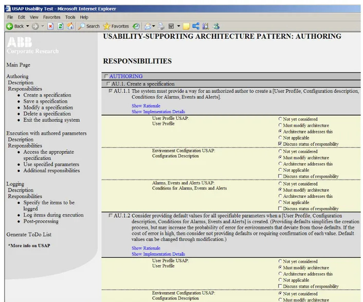
The ease-of-use and ease-of-understanding goals are reflected in the tool by hiding the pattern language concepts of foundational USAPs and end-user USAPs from the user. The USAPs concept is instead visualized as a presentation of the foundational responsibilities hierarchy in the navigational menu without using the words “Foundational” or “End-User” (see Figure 2). In the main window each foundational USAP’s responsibilities are displayed with a pattern language parameter furnished by the prioritized end-user USAPs: Alarm & Events, User Profile, and Environment Configuration. Each responsibility has a checkbox that is not checked by the architect, but by an internal state that is only is set to “check” when the designer has changed the state of the radio-button associated with each end-user USAP related to the responsibility. The radio-buttons states are set by the designer and reflects hers/his architecture’s state in relation to the responsibility and these are: “Architecture addresses this”, “Must modify architecture” and “Not applicable”. The state “Not yet considered” is the default state set when the designer has not yet made an active choice. The user can only make an adequate choice after reading the responsibility text thoroughly. Otherwise it would be difficult for the user to know her/his design’s state in relation to the responsibility.
The entire layout of the USAP delivery tool was consciously made simple and direct. Additional informational text was hidden and displayed only when the user choose to display it by clicking a link, e.g. “Show rationale” for a responsibility. The help text could be hidden again by clicking a link, e.g. “Hide rationale.” We felt that the information content otherwise would be overwhelming for the users. The main page contained instructions on what a USAP is and how to use the USAP delivery tool. The states of the radio-buttons and checkboxes are persistent as
long as the web-tool is open, enabling the user to go back and forth in the tool without losing data. Since the delivery tool was a prototype we did not take it to the level of a full-fledged content management tool with a database as the backbone. We wanted user feedback from the tests to inform the design before investing in this more expensive development step.
Figure 2 shows a screen shot of some of the responsibilities. If the designer wishes to discuss the responsibility with the remainder of the design team or other stakeholders, a check-box “Discuss this” can be checked by the designer. A future extension would be to add the possibility of including a comment for each responsibility.
The interface of the tool encourages the designer to set the state of hers/his architecture in relation to each responsibility. The checkboxes next to each responsibility indicates to the designer whether the responsibility is fully considered for each USAP or not. These features are intended to address the problem that appeared in the
laboratory studies of subjects not responding to half of the responsibilities.
It is also worth noting that the name of each of the three USAPs chosen for delivery is enumerated under the responsibility, and that the designer must respond to each responsibility in the context of each USAP. It is possible that state of the architecture will vary among the USAPs. Making the state of the architecture explicit with respect to each of the different USAPs will encourage the designer to consider each responsibility’s applicability for each USAP. Presenting the three instances of each responsibility together, instead of organizing them by their USAP, encourages the architect to consider common design solutions.
Finally, observe that under each responsibility is a link that when clicked displays the implementation details as discussed above. When we discuss the results of using this tool, we will discuss how the designers made use of this feature.
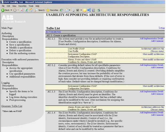
Once the designers have considered and responded to all of the responsibilities, they can generate a “to do” list. This is a list of the responsibilities that either have not yet been considered or that require a modification of the architecture. Figure 3 shows a screen shot of the “to do” list generated by the screen shot in Figure 2. The “to do” list can then be incorporated into whatever project management scheme the designers use.
7. Results of using the USAP delivery tool
The two software architects from the product line system project used the USAP delivery tool at a time when they had completed a preliminary architecture design. One architect was senior and had created most of the preliminary design. The second architect had recently joined the project but had a solid background as software architect at an automobile company.
The Authorization foundational USAP was omitted from the test we performed in order to make the number of
responsibilities tractable for a single day of testing. Since for the product line under development, authorization would not be needed, this did not impact the utility of the test from the point of view of evaluating the current design for support of the three chosen usability scenarios.
The two architects from the product line system project used the USAP delivery tool in one session lasting six hours interrupted by a one hour break for lunch and two 15-minute breaks for coffee. They examined and discussed each responsibility in turn, made notes as appropriate, and decided what response to make to that responsibility. In the six hours of work they completed consideration of all of the responsibilities for each of the USAPs. They averaged about 12 minutes per responsibility.
Overall the designers felt that the USAP delivery tool was quite helpful. Some of the quotes regarding the helpfulness of the tool:
Designer 1: Yeah, I, I think it’s, it’s a very easy way to get some kind of review of your work. You will not get the complete picture of all your work, but it
will be a very good check, or at least an indication of the completeness of your system. The main goal for ABB when applying the USAP technique was to incorporate usability support early in the design process in order to build in the support in the core architecture. By building in usability support early in the architecture, ABB expects to avoid late and costly redesign after the users have tested an actual version of the product line systems products. Some of the quotes that related to the goal of early architectural usability support were:
Designer1: We have discussed lots of internal stuff in the system but this gave us some picture of what the user is going to see.
Designer2: And that is things that we were not going to get that input, until very late in the design process, if we hadn’t used this tool now. So it was good to have these points of view come in this early. I think we have identified at least a couple of new subsystems.
Designer1: Yes. And some shortcomings of the previous design.
Designer2: Yeah.
The designers also responded well about the level of abstraction of the responsibilities:
Designer2: The tool raises very abstract discussions and thoughts. It is much work to go through these responsibilities.
Designer 2: The most useful thing with this tool is that it guides your thoughts, and it helps you to think about the architecture that you have from different perspectives.
From preliminary reactions at another ABB business where we showed the USAPs before removing the UML example and developing the pattern language, we were concerned that the designers would feel “supervised” or that they would feel that they had received unwanted and/or unhelpful recommendations. Instead, the reactions were very positive:
Designer 1: It was like having a partner to discuss with. Designer 2: The issues that you list in your tool, when you
are sitting several people talking together about them, then you have to discuss how we handle these issues in our system, in our architecture. And that, that provides an understanding for the peoples who are important in the discussion, of how the architecture works.
In contrast to the earlier negative reactions to UML diagrams of a sample solution, we found that as the designers examined the lists of responsibilities, they nearly always examined and discussed the implementation suggestions. One of their suggestions for improvement of the tool was that the implementation suggestions could be
automatically included in the to-do list so that they would be available for future use, indicating that they saw these suggestions as useful instead of intrusive.
In summary, the reactions of the software architects to the tool were very positive. The designers had viewed all implementation details in a top-down fashion indicating that for every responsibility they felt it helpful to view the implementation guidelines. They also asked for a copy of the tool so that they could have it available as they worked through their to-do list.
During their use of the tool, the architects identified 14 issues that needed further consideration. Over the next several weeks, the architects considered these fourteen issues and their actual impact. The architects’ judgment as to the resolution of each of the issues is detailed below. Issue 1. Cost Saving: - would have been done any way Issue 2. Cost Saving: - 1weeks
Issue 3. Cost Saving: - weeks
Issue 4. Cost Saving: - would have been done any way Issue 5. Cost Saving: - very uncertain of value Issue 6. Cost Saving: - very uncertain of value Issue 7. Cost Saving: - very uncertain of value Issue 8. Cost Saving: - 1 weeks
Issue 9. Cost Saving: - very uncertain of value
Issue 10. Cost Saving: - would have been done any way. Issue 11. Cost Saving: - very uncertain of value
Issue 12. Cost Saving: - 2 weeks, could be more if this idea is fully exploited
Issue 13. Cost Saving: - very uncertain of value Issue 14. Cost Saving: - very uncertain of value
For the issues where the architect felt secure in providing a value, 5 weeks were saved. Note the uncertainty of the architect with respect to many of the other issues. In the worst case, this uncertainty translates to no additional savings but, likely, there were additional savings beyond that estimated initially. In any case, saving 25 days (5 weeks) for less than one day of investment by two people is still an amazing result.
The savings does not include the time the researchers have invested in producing the USAPs but Alarms and Events and user profiles are common usability scenarios. These USAPs are reusable across many projects and thus the investment to produce them will get amortized across multiple projects.
8. Conclusions and Future Work
On the one hand, providing professionals with a check list of activities they should perform is a very old concept. Computerizing the checklist is not a major step. The resulting tool is extremely simple. On the other hand, getting a 25-to-2 return on investment (ROI) for the architects - one day’s work by two people saved five weeks - is an amazing result. One study with one estimate is not
scientific evidence but this study is one of the few reports of ROI with respect to the use of any architectural technique. Architectural knowledge can be encoded into very simple tools and still be effective. Architectural tool builders might consider simple methods to encode their knowledge rather than attempting very sophisticated tools.
Furthermore, three aspects of this work are significant. 1. The patterns are primarily described at the level of
responsibilities. These are independent of implementation, and lead the architects to think about how a particular responsibility relates to their current system design rather than forcing them to attempt to compose structural instructions with their current design.
2. Using textual descriptions for implementation instructions rather than diagrams was well received by the architects at ABB. The push back from architects with respect to diagrammatic instructions has not previously been reported.
3. Encouraging the architects through a tool to examine all of the items in the checklist removes the problems with paper delivery of the checklist. In addition, there is nothing in the USAP delivery tool that is specific to usability patterns. Any quality attribute where the requirements can be expressed as a set of responsibilities, e.g. security, could likely be included in the tool. The same portions of a system could then be represented in both a security responsibilities implementation details and in a usability responsibilities implementation details.
Acknowledgements
The Software Engineering Institute is a Federally Funded Research and Development Center created by the US Department of Defense. A portion of the third author’s time on this research was funded by the Institute of Education Sciences, US Department of Education, through Grant R305B040063 to Carnegie Mellon University, and by ABB. The views and conclusions herein are those of the authors and should not be interpreted as representing the official policies, either expressed or implied, of IES, SEI, the U.S. Government, or ABB.
References
[1] Adams, R. J., Bass, L., & John, B. E. (2005) Applying general usability scenarios to the design of the software architecture of a collaborative workspace. In A. Seffah, J. Gulliksen and M. Desmarais (Eds.) Human-Centered Software Engineering: Frameworks for HCI/HCD and Software Engineering Integration. Kluwer Academic Publishers.
[2] Alexander, C. (1977). A Pattern Language: Towns, Buildings, Construction. USA: Oxford University Press. ISBN 978-0195019193
[3] Barbacci, M., Ellison, R., Lattance, A, Stafford, J., WeinStock, C, and Wood,, W., “Quality Attribute Workshops, 3rd Edition”, TECHNICAL REPORT CMU/SEI-2003-TR.016, Pittsburgh, PA, 2003.
[4] Buschmann, F., Meunier, R., Rohnert, H. and Sommerlad , P., Pattern-Oriented Software Architecture Volume 1: A System of Patterns, Wiley, 1996
[5] Clements, P., Northrop, L., Software Product Lines: Practices and Patterns, Addison Wesley, 2001.
[6] Folmer, E. (2005) Software Architecture Analysis of Usability, Ph.D. thesis. Department of Computer Science, University of Groningen, Groningen.
[7] Folmer, E., van Gurp, J., Bosch, J. (2003) A Framework for capturing the relationship between usability and software architecture; Software Process: Improvement and Practice, Volume 8, Issue 2. Pages 67-87. April/June 2003.
[8] Golden, E, John, B. E., & Bass, L. (2005) The value of a usability-supporting architectural pattern in software architecture design: A controlled experiment. Proceedings of the 27th International Conference on Software Engineering, ICSE 2005 (St. Louis, Missouri, May, 2005).
[9] John, B. E., Bass, L, Golden, El. Stoll, P. A Responsibility-Based Pattern Language for Usability-Supporting Architectural Patterns. Proceedings of the Engineering Interactive Computer Systems conference, Pittsburgh, Pa, July 2009., ACM Press
[10] John, B. E., Bass, L. J., Sanchez-Segura, M-I. & Adams, R. J. (2004) Bringing usability concerns to the design of software architecture. Proceedings of The 9th IFIP Working
Conference on Engineering for Human-Computer Interaction and the 11th International Workshop on Design, Specification and Verification of Interactive Systems, (Hamburg, Germany, July 11-13, 2004).
[11] Juristo, N., Moreno, A. M., Sanchez-Segura, M. (2007), “Guidelines for Eliciting Usability Functionalities”, IEEE Transactions on Software Engineering, Vol. 33, No. 11, November 2007, pp. 744-758.
[12] Stoll, P., Wall, A., Norström, C.: Guiding Architectural Decisions with the Influencing Factors Method. WICSA. IEEE, Vancouver (2008)
[13] Stoll, P., John, B. E., Bass, L. J., Golden E. (2008) Preparing Usability Supporting Architectural Patterns for Industrial Use, Proceedings of the International Workshop on the Interplay between Usability Evaluation and Software Development (Pisa, Italy, September 24th, 2008)
[14] Tidwell, J. (2006), Designing Interfaces: Patterns for Effective Interaction Design. O’Reilly Media: Sebastopol, CA.