---..
ANALYT1CAL METHODSfor Use On
OIL SHALE AND SHALE OIL
..
CONTENI'S Introduction Section A. A-l.
A-2.
A-3.A-5.
A-G.
Section B. B-4. B-5. Section C. C-l. C-2. C-3. C-4 .. C-5. C-6. C-7. Section D. D-l. Section E.Oil Shale Analysis
Oil Yield by Modified Fischer Assay Laboratory Sampling of Oil Shale
Determination of Mineral Carbonate in Raw and Spent Oil Shale )[ethod A. Absorption of Carbon Dioxide
Method B. Volum~trie Determination of Carbon DioxIde Combustion Analysis for Carbon and Hydrog~n in Oil Shale and Its Products
Gross Heating Value of Raw Shale
Determination of Ash in Raw and Spent Oil Shale Crude-Shale-Oil Analysis
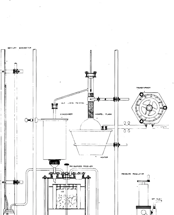
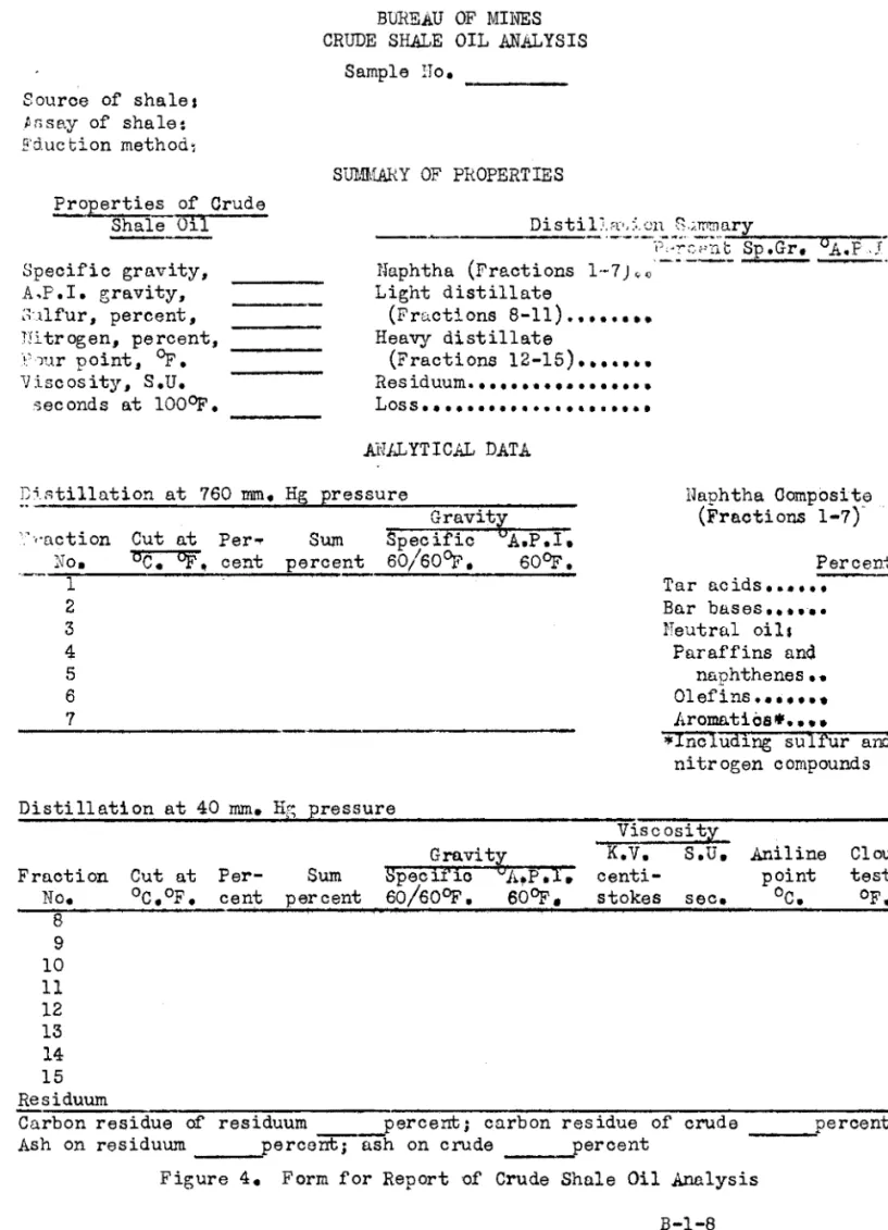
Analysis of Crude Shale Oil Dehydration of Crude Shale Oil
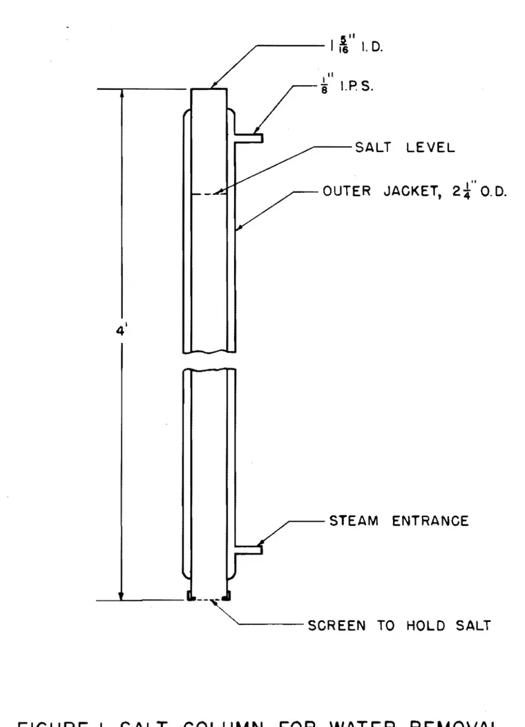
M''lthod A. By M?ans of Salt Column
Methoc B. By Means of Cor,-cinuous Distillation Method Method C. By Means of ')';'"'1 Dryine; ~n:cthod
Specific Gravity of Oil Se.m;:df'5
Method A. By MeaIl:s of::'c'c'ln::.f'ic Gravity Bottle
~thod B. By Means of r':;:ntte
Nitrogen Determination by th0 Kjeldahl ~~thod
Distillation in Semi-Micro Apparatus
Analysis of Gasoline-Bailing-Range Hatl'.lrials
HydrooarbonGroups by Silioa Gel Adsorption Method Tar Acids and Tar Bases
Olafins by Ni trogan Tetroxide Meth-Od Copper Dish Gum Content of Gasoline Doctor Test
Butyl Mercaptan Test for Eremental Sulfur Mercaptan Sulfur in Gasoline
Analysis of Di"lsel-Boiling-Range Materials Hydrocarbon Groups by Silica Gel Method Analysis of Heavy Distillates
i
~---,
Section F. F-l. F-2. F-3. Section G. Section H. Seotion J. J-l. J-2. J-3. J-4. J-S. J-6. J-7. J-8. J-lO. J-ll. J-l2. J-13. J-14. J-l5. J-16. J-l7. J-18. J-19. J-20. J-2l. J-22. J-23. J-24. J-2S. J-26. J-27. J-28. J-29. J-30.Analysis of Rp-sidual Materials
Determination of Asphaltenes, Oils, and Resins in Asphalts Olil-msis Spot Tp.st for Asphaltio Materials
Modified Oliensis Spot Test for Asphaltio Materi~ls
Analysis Methods for Use on Other Products (Tar Acids, Tar
Bases, Wax, etc.) \.
Misoellaneous Analysis Methods
Determination of Condensable Hydrocarbons in a Retort Gas Stream
ASTM Analysis Methods Vihich Have Been Tested on Oil-Shale or Shale-Oil Samples
Pyranetric Cone Equivalent (P.C.E.) of Refractory Materials Unit Vieight of Aggrega1Se
Determination of Bitumen
Penetration of Bituminous Materials
Loss on Heating of Oil and Asphaltic Compounds
Softening Point of Bituminous Materials, Ring and Ball Method Flash Point by Means of Tag Closed Tester
Specific Gravity of Road Oils, Road Tars, Asphalt Cements, and Soft Tar Pitches
Distillation of Gasoline, Naphtha, Kerosine, and Similar Petroleum Produots
Viscosity by Means ot.the Saybolt Viscosimeter Flash and Fire Points by Means of Open Cup
Flash Point by Means of Pensky Martens Closed Tester" Water in Petroleum Produots and Other Bitumin!'Us Materials Water and- Sediment in Petroleum Produots by !&lans of
Centrifuge
Cloud and Pour Points
Ductility of Bituminous Materials
Sulfur in Petroleum Oils by Bomb Meth"od
Detection of Free Sul~lr and CorrosiVe Sulfur Compounds in Gasoline
Color" of .RefinAd Petroleum Oil by Means of Saybolt Chromometer
Distillation of Gas Oils and" Similar Distillate Fuel-Oils Proportion of Bitumen Soluole in Carb.on Tetrachloride Burning Quality of Kerosine Oils
Conraijson Residu~ of Petroleum Products Volume-Temperature ~orreotions
Thp.rmal Value of Fuel Oil
Laboratory Sampling and Analysis of Coal and Coke"
Gravi ty of Petroleum Products by Means of the Hydrometer Vapor Pressure of Petroleum Produots (Reid MAthod)
Visoosity-Temperature Charts for Liquid Petroleum Products Knook Characteristics of Motor Fuels by the Motor Method
f J-34. ,J-35. J-36. J-37. J-38. J-39. J-40. J-4l. J-42. J-43. J-44. « : : / _ - - - .... - - - - -...~
Existent Gum in Gasoline KinAITmtic Viscosity,
Conversion of Kinnmatic Viscosity to Saybolt Universal Viscos ity
SedimAnt in Fue 1 Oil- By Extraction Acid Heat of Gasoline'
Ash Contnnt of pptroleum Oils
Rnmsbottom RAsidue of Petroleum Products Oxidation Stability of Gasoline
Calculation of Viscosity Index ..
.tl.niline Points and Mixed .ll.niline Points of PAtroleum Products
Isnition Quality of Diesel Fuels by the Cetane Method Acid and Base Numbers of Oils by Color Indicator Titration
~l.cid and BasEl Numbers of PFltroleum Oils by Electrometric
Titration
Knock Charact"!ristics of Motor Fuels by the Rl'lsAarch Method
p
INTRODUCTION
-This book is design0d for the purpose of sharing infonmation concerning the applicability of various analytical proMdures to oil shale, shale oils and shale-oil products. M~thods are included
herein only after they have been tried on such materials. Modifica-~
tions and additional instructions'which o.re found to be necessary are most important. Infornmtion concerning limited applicability or
accuracy is o.lso d~sired. In addition the book should serve to standardize methods of test in tho various laboratori~s working on oil shale and shale oil.
The methods presnnted include the work of many individuals from both the Oil-Shale D~monstration Plant and the Petroleum and Oil-Shale Experim;;)nt Station. lihilF, thFlir work is appreciated, it is not
feasible to recognize each person who participated.
Preparation of the book in this fonm at thA present time is for the purpose of allowing wide distributIon in the laboratories. It is aamittedly a pr~liminary version-of the book that should ultimately be attained, but should serve the purpose of 'stimulating discussIon
and research to improve it. Revisions will be made at reasonable intervals and supplp~nts will be issued when necessary.
SUggestions for improvement of any of the methods are always welcome. Additional methods for inclusion are--desirable as are
suggestions for methods which should be included. Such additions and suggestions may be s9nt to the unde'rsigned. They will then be' circulated to th8 laboratories most interested for additional comment and, if no adverse COIDmFlnt results, included in the next addition.
JOHN S. BALL
Chairman~
Committee on Analytical Methods
iv
f
SECTION A
Methods for Oil Shale Analysis A-l. Oil Yield by Modified Fischer Assay
A-2. A-3.
Laboratory Sampling of Oil Shale
Determination of Mineral Carbonate in Raw and Spent Oil Shale Method A. Absorption of Carbon Dioxide
Method B. Volumetric Determination of Carbon Dioxide A-4. Combustion Analysis for Carbon and Hydrogen in Oil Shale and
its Products
A-5. Gross Heating Value of Raw Shale
A-6. Determination of ~h in Raw and Spent Shale
See also the following methods from other section of this report. B-4. !'litrogen Determination by the Kjeldahl Method
J-l. Pyrometric Cone Equivalent (P.C.E.) of Refractory Materials
J-2. Uni t ~·/eight of Aggregate
J-8. Specific Gravity of Road Oils, Road Tars, Asphalt Cenents and
Soft Tar Pitches
J-26. Laboratory Sampling and Analysis of Coal and Coke
--~---ASSAY OF OIL SHALE BY THE MODIFIED FISCHER RETORT
(Method A-I)
SCOPE
The method of assaying oil shale by the modified Fischer retort proposed by Stanfield and Frost (1) has been used for several thousand determinations at the Laramie, Wyoming and Rifle, Colorado stations of the Bureau of Mines. In the light of this experience a more detailed description of the procedure is given which includes precautions that should be emphasized for proper appraisal of oil shale. Although these precautions are normally practiced by the careful analyst, experience has shown the advisability
or
oalling attention to them. as a uniform guide for the assay of oil shale.APPARATUS
A single retorting assembly for the assaying of oil shale by the moditied Fischer method is shown in figure 1. The numbers on this figure refer to the individual items given belews
1. Adjustable support for cooling hath. This support should be adjustable for total heights of approximately 4 to 7 inches. Wooden blocks may be substituted it desired.
2. Cooling bath.
A
400~1. beaker is satisfactory.3. Centrifuge tube. California-type, long form. with tooled neck and sand-blasted spot for marking, 100~1. capacity. Graduated from 0 to 1
mI.
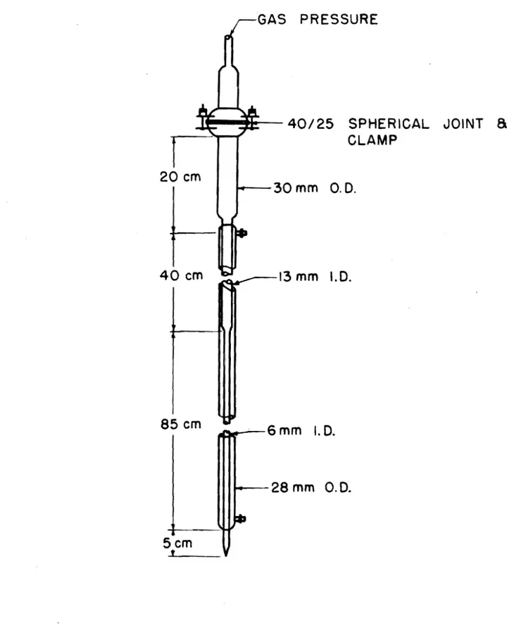
in 1/20-.1. subdivisions, from 1 to 3 ml. in 1/10 ml., from 3 to 6 mI. in 1/5 mI., from 6 to lO'ml. in 1/2 mI., and from 10 to 100 mI. in 1 mI.4. Pyrex glass adapter constructed as shown in detailed drawing at the end of this report.
5. Condenser, Allihn-type, Pyrex glass, with 24/40 standard taper joints and drip tip on lower end. Jacket length, 300 rom. For a single retort assembly, this condenser may be supported by a heavy ring stand and clamp; for an assembly
of retorts, the condensors may be supported by rods and clumps affixed to the retort support (item 11).
6. Heat insulating shield. The preferred type of shield may be constructed by coating a form made of 4 mesh-per-inch galvanized wire screon or metal lath with asbestos c~ment
or similur insulating material. This shield shoul,d be approximately 1 inch thick and be spaced approximately 1/2 inch or more from the body of the retort. A piece of trans ite pipe, with lid, may also be used ..
7. A thermooouple with pyrometer or potentiometer capable of
measuring temperatures at 5000
+
50 C. This thermocouple should be checked occasionally to make sure it is function ing properly.8. Modified Fischer cast~aluminum retort as shown in detailed drawing at the end of this report. The matting surface of the aluminum plug is 1-3/8 inches long. This extra long surface is to prolong the life of the plug. As the plug is worn by grinding and seats further into the retort, it is necessary to machine off the bottom of the plug in order that it does not obstruct the distillate outlet. The dis tillate outlet tube fran the retort may be of brass, stain loss steel, aluminum, or other suitable metal.
9. Iron grate support and wire gauze between burner and retort. The nichrome wire gauze aids in distributing the heat and preventing sweating of the aluminum retort due to localized heating. The use of the gauze is optional.
10. High-temperature, Meker-type, gas burner.
11. Retort and burner support. This support oan be constructed of a I-inch angle iron and 3/4-inch transite with rods and clamps to also support the reflux condonsers (item 5). For
.,... a single retort assembly, a 'conventional heavy ring stand
may be used.
12. Neoprene stopper with one hole. 13. Cork with one hole.
14. Nooprene stopper with one hole.
15. Right-angle glass tube to vent fumes to hood. PROCEDURE
Preparation of Sample
A one~pound sample is desirable for assay. This sample should
have been prepared by the use of appropriate sampling procedures and be representative of the source material. The sample is crushe4 rapidly and completely to -8 mesh by passing it through a jaw-type crusher. After each pass through the orusher the material smaller than -8 mesh is removed ~ sieving so that a minimum wmount of fines is present. The combined portions of the crushed sample are thoroughly mixed, and about a l25-~ram representative portion of this freshly
orushed material is removed by means of a small riffle or cone-type sampler. This portion is placed in a sealed container for the deter mination of total moisture, which is determinod as soon as convenient ani reported as total moisture nas received.tI
15 100 ,...1 cenhlfu.~e tu.b8'- 2 vent to e )(hnust 9
f';;URE lOlL SHALE RETORTING UNIT
/
A representative portion of the crushed sample in sufficient quantity for assay is removed by means of a sampler and dried in an oven at 1060e. (22lor.) for one hour17. Samples of the orushed shale
g
Oven drying may be omitted for samples to be a.ssayed on the "as roceived" basis"appearing wet must be given a prGliminary drying at roam temperature. Oven drying for extended periods is not desirable as it may causo a reduotion in oil yield.
Preparation and Assembll of Retort
The ,joint between the retort and plug should be gas tight. This is tested oooasionally by immersing the retort with plug in place in a water bath and applying air under slight pressure (as 5 to 10 inohes
of water pressure) through the distillate outlet tube. Vihen the joint is foUnd to leak, the plug, is reseated by grinding with a fine abrasive (100 mesh or smaller), then coated with a light fi 1m of graphite or graphite-oil lubricant to form an air-tight seal. The lubricant also serves to prevent the plug from stioking in the retort.
A
100.0-gram charge of the freshly dried shale is weighed into a tared weighing dish, then charged into the retort in five layers. The layers of the shale are. separated by aluminum disks about a oentral vent tube as, shown in figure 2. Care should be taken in oharg~ng the retort to provent loss of sample as dust or by pouring a portion of it down. the distillate outlet of the retort. Tho plug is tapped lightly into place, and the, assembl,ed retort is weighed to tho nearest 0.1 gram. The centrifuge tube, stopper, and adapter are weighed and re corde' to the nearest 0.01 gram, and the apparatus is assembled as shown in figure 1. ,All joints 01 the apparatus must be gas tight. Brine or any other suitable anti-freeze solution at oOe • • 50 (32Op.)is ciroulated through the condensers am is plaoed in thO-COOling bath about the bottom of the centrifuge tUbe. (The temperature
or
thisoooling~bath should not be allowed to rise above 37.800. (lOOor.).)
An
exhaust fan or fume hood is desirable to remOVe the obnoxious vapors which may be evolved during the retorting operation.Ret ort iIl5
The burner is ignited and adjusted so that tho retort temperatures below 50000. are within
+
100e. of those shown in figure 3. After heating for 40 minutes a-temperature of 5000+
50e. is maintained untilretorting is complete. At tho end of 60 minutes the for~tion of oil should be oomplete for all but the riohest oil shales. ~il shales yielding more than 70 gallons of oil per ton of shale (approximately 29 ml. of oil for 100 grams of &hule) occasionally require 10 to 20 minutes of additional heating before oil formntionoeuses. When no further oil is formed, the flame is removed and the apparatus is cooled. The cooling may be aooelerated by means of an eleotric fan. The cooled retort is weighed. The weight of the retort and spent shale
subtracted from the weight of the oharged retort gives the loss in weight of the shale by retorting. This loss minus the weight of re,covered oil ani water is the vleight of gas plus loss.
When the oentrifuge tube and adapter have reached room tempera ture, they ure removed and weighed to determine the weight of, oonden sate. The condensate in the centrifuge tube is warmed to approximately 37.8oC. (lOOar.) and then centrifuged to effect a good separation of the oil and water. Assuming the water or aqueous layer to have Q
specific g~avity of 1.000 at roam temperature, the yolume of water in milliliters is reported as the weight of water ih grams.
The oil layer is removed to a separate container and is generally sufficiently free of water for the dotermination of specifio gravity. When furthe~ drying is necessary, anhydrous sodium sulfate may be used. The dry oil is mixed thoroughly to obtain a homogeneous s~pleJ
and its specific gravity is deter.mined at 37,8 0C. This may be done conveniently with a small pipette having a capacity of fram 0.7 to 2.0 ml. The specific gravity values determined at 37,80/37.80C. (lOOO!lOOOf.) are then oonverted to l5.So/l5,SoC •. (soo/soOf.) by means
at
the table given below.Observed specific gravity at 37.8°(37.80 C. 0.800 to 0.843
To convert to specific gravity at l5.So/l5.60C., add to the observed specific gravity the follOWing correctionsl
0.010 0.844 to 0.91S
0.917 to 1.000 0.008
These corrections were obtained by oonverting the speoific gravities determined at 37,80/37,80C. to 37.80/l5.6 0C. by multiply ing by the factor 0.994, (density 'of water at 37,8°/density of water at l5.SoC.) then converting these values to speoifio gravities at l5.So/l5.SoC. by the use of standard oonversion tables (2),
The yield by volume in milliliters is then oalculated br dividing the weight of oil in grams by its specific gravity at l5~6o/l5.60C.
This calculated volume of oil multiplied by the factor 2.397 (for 100-gram oharge) gives the gallons of oil per ton of shale. The water in gallons per ton of shale is obtained by multiplying the volume of water in milliliters by the above factor. For weights of
charge other than 100 grams, the yields of oil and water per ton of shale are obtained by the following formulas
Gallons of oil (or Vlater)
=
Milliliters of oil (or water) x 239.7 per ton of shalo Grams of oil-shale chargeWhen there -is insufficient oil for an accurate specific gravity determination by the pipette method, the volume of oil from the shale is approximated from its wei$ht and an assumed specific gravity of 0.950 at l5.60/15,60C. (SOO/SOOF.). This method of estimating the
\ I,
I
L
----215_,- M---M_ ~4511.,---J I L7~.II, 11_, ~20 •• /. "140 ITAIICIolIllO T.t.I'£R JOINT ." l5 c:: ;:0 ",/"
,~,
r..:I '~ , .111 ..~
/_ "" / ",,, " 01 TAPIR~
V
"-101I1I.~rN9T
8UREAU OIF MINES PlT~UII • OI~ SHALl rlCPllllllrllT ITAT_ ~AIIA"'I. W'tOIiIIIIII. _: PYM:X GLASS ADAPTER --, USE IN CONJUNCTION WITH MODIFIED FISCHER ALUMINUM R[TORT _.: FEB, 27. 1948 S8R-241P ... I or I _ ... .... 1.1 FUll SIZE ,JtAGIO .. 0.(;,1'4~
3>~
..
" -/
I f--o
I
II
IJ
//
/
v
/
IT J/
II
I
~ I I i IV
...
,.;V~
IV
V
V
V
f-- I/
- - II
/
! 1 j c---I
500 400cP
w a:: ::::> 300 ~ a:: w 0... ~ w I 200 100o
10 20 30 40 50 60 ELAPSED RETORTING TIME. MINUTES ..".FIGURE
3.
RETORTING
RATE
FOR
MODIFIED
FISCHER
ASSAY.
I....
I ....aoil yield by volume is more aocurate than attempting to read the volume of the oil directly in 0. oalibrated centrifuge tube.
Determination of MOisture in Oil Shale
•
Approximately a 50-gram sample of the shale set aside for
moisture determination is weighed rapidly to the nearest 0.1 mg. into a shallow oruoible or dish and heated in an oven with natural air oirculation at 1050C. (220OF.) for one hour, after which it is cooled in a desiccator and weighed. The loss in weight multiplied by 100 and divided by the weight of sample is taken as the peroent moisture in the sample.
~te,rmination of Coking Tendency (Optional)
If desired, the shales are rated as to their ooking tendenoy by observing the retorted shale from the Fischer assay. This coking tendency is rated as followsl
Coking rating
None The spent shale pours oompletely from the retort similar to sand without any evidenoe of conglomeration.
Slight Th~ spent shale adheres together but can be oompletely removed from the retort by stir ring with a spatula.
Moderate The shale is partially fused but oontains some unfused particles. It is diffioult to remove from the retort and requires the use of a metal soraper or ohisel.
Heavy All shale particles have lost their orig inal physioal identity. The residue is very difficult to remove from the retort and must be ohipped oUt mechanioally. CALCULATIONS
Unless otherwise stated" all calculations are made on the oil shale dried as desoribed und~r ~reparation of Sample." The oaloulations on dried oil shale may be oonverted, if desired" to the "as reoeived" basis in the following manner,
Peroent of produot in sample _ peroent of produot x 100 - L
on the nas reoeived" basis - in dried sample 100 where L is peroent moisture by oven drying.
A-1-8
--~-
f
PRECISION
Duplicate assays by the same or different operators should not differ by more than the followings
oil
yield, Allowable difference tram the average gallons per ton of duplicate assays, 6allonso
.. 36.0+
0.5 36.1 - 44.0+
0.6 44.1 - 52.0+
0.7 52.1 - 60.0-
+
0.8 60.1 - 68.0 Above 68.0PRECAUTIONS AND ADAPTATIONS
To obtain the precision given in the above table, the following preoautions should be observed.
1. The sample must be mixed thoroughly and be representative of the material submitted for assay.
2. All equipment should be cleaned and dried prior to each assay. Special attention should be given the distillate outlet of the retort as it tends to accumulate shale dust, oarbonized material, and oil.
3. The retorting system must be gas tight. As a preoaution against loosening of the retort plug, it is advisable to tap the plug lightly after heating has commenoed and prior to the evolution of vapors from the sample.
4. The proper heating rate must be maintained within the pre scribed limits, To insure correot temperature measuremenbs, the pyrometer must be'checked or standardized periodioally, 5. The temperature of the cooling medium oirculating through the
condensers must be maintained at a temperature of 00
+
50 C.(320
+
gor.) for all assays.6. The retorted oils must be free of water and be mixed thoroughly before making specific gravity dete~inations.
7. Undor humid atmospheric conditions, precautions must bo taken against the adsorption of wuter on tho spent shale in the re tort. A culcium chloride drying tube attached to tho distillate
outlet during tho cooling period will eliminate possibl~ error fram this source.
Ueasurement of Evolved Gases
The yield of non-condensed gases formed by the assay of oil shale in the Fischer retort can be determined, when desired, qy collecting the gas in a calibrated gas holder. The gas holder uses an acidified saturated aqueous solution of sodium sulfate to form the liquid seal. Before starting the retorting operation, the retort assembly and gas holder must be checked carefully for leaks qy applying a negative pressure on the gas holder, If the system is found to be gas-tight, the sample is retorted and the gas collected. The volume of gas at atmospheric pressure and its temperature are measured, and from these values the corrected gas volume may be calculated. The gas volume is reported water-free at 60or. and 30 inches (762 rom.) of mercury pres sure. The following formula may be used to correct gas volumes to these ~onditions,
v
~ v x l5.6 oC.+
273 x(i -
p) T+
273 762where V
=
Gas oorrected to 60OF. and 30 inches of mercury, dry basis v=
Observed volume of gas in litersT ; Temperature of gas P
=
Atmospheric pressurep
=
Vapor pressure of water at temperature TV x 320.37
=
Cubic feet of dry gas per ton of shale at standard conditionsREFERENCES
1. Stanfield, K, E., and Frost, I. C., Method of Assaying Oil Shale by a Modified Fischer Retort; Bureau of Hines Report of Investi gations 3977, 1946, 11 pp.
2. National Bureau of Standards, National Standard Petroleum Oil Tables; Circular C4l0, Uarch 4, 1936.
f A L, J A SECTION C-C A014 HOLE -. , OIA SECTION B-B
UNIT(O STATES DEPARTMENT OF lNTER10R
SURUU OF "I~E$_ _ _ _ _ _-I
P(TtM:l(.(UN • ou., SMALt: fllPERltlCMr STaTIO. B
RETORT
MAT'L ·CA~n ALUMINVM
zt 0104. CORE M I V ..1 SECTION A-A
All RAOtF t vNLESS Of HER WISE SPECIFIEO
V INDH~ATF.S FINE MACHINE SURFACE
~ INDIC4fES MEDIUM MACHIHE SURFACE
lol...E. WYO.",", . MOOIFIED FISCHER CAST Al..IJMlHUM RETORT
...
fOR TtiE ASSAY OF OIL SHALE
SIZE .~I.: rtB. 27, 1948
-242P
TItMIlD... I : O - - W
. .M LCF I<.ES ...rn I IW 2~n
-f
G/
I ,....• I OtA. MOLE a HOLts " OIA. EQUALLY SPACED I -i SQiJARE~
4!1" APART \ ON II 014 CIRCLE --I •
, ,~ , I ~ a I ai. a
,
" e HOLfS .. 01' I 'a MOLES 'OIAEQUALLY SPt\C(O I£QvALH SPACED
, i\ I
io 4~APART '--1 4 , . APART
C~ lit DIll, CIRCLE ON II 0141. CIRCLE
i\ io I ,
I
,
DISK"AT'L-AL~M SHEET :.. rOIA-WHOLES !> REQ'D_ FOR ONE COMPLETE ASS£M8l'l
YENT TUBE
".T't -ALUMINUM BAR STOel(
~ F"INtStl ALL OVER -'1
'0
DISTILLATE OUTLET TUBEMATl -8RA$S OR OTHER SUITABLE METAL
- f - ••'- 'i
I~
PLUG
MAT'L - ALU;;;;U.. BAA: srOCf( ~
,MOICA,TES MEDIUM M'CtitH! F'iNI5M UNLESS OT"(AWI5£ NOTED FINISt1 ~ ALL OVER v INDICATES FINE t.iACHI"tE FINSH
UNITED STATES DEPARTMENT OF INTERIOR
SURr4u Of IIIINrs
r-;;;":;;T';;;O:O"';-;u.;;-,:.,,,,;-;-,'so;I'IAI.££XnRIIffiit-ifiliTtON 1. ...111(. 'M'VOMING
5
p
RUBBER TUBING -~ -RETORT COOLING BATH- -~-FI3LRf: 6UNIT FOR COLLECTING GAS FROM MODIFIED FISCHER ASSAYS
SBR-451
---~
9119/49
~---r
FROM GAS
.
Ir-t._ _r-COLLECTION CHAIoIBER
CALCIUM CHLORIDE
u-TU8E
GAS COLLECTION BULB
RUBBER TUBING MERCURY MANOMETER IaCUUM PUMP 110 It
o
FI;:;liRE 7UNIT FOR DETERMINING SPECIFIC GRAVITY OF GAS.
SBR-4~
~---LABORATORY SAlIPLurG OF OIL SHALE (~iethod A-2)
SCOPE
Th~ following procedures are intended to covor the following$ 1. Laboratory sampling of both raw and spent shale from
the Royster and N-T-U retorts.
2. Laboratory sampling of oore and ohannel swmples reoeivod fran the mining section and other sources.
3. Sampling of standard assay samplos. APPARATUS
The apparatus used for sampling oil shale oonsists of the followings a. Crushers'" A Denver Fire Clay jaw crusher size No.2 is
used.
b. Large Rifflo Sampler' - lO" by lB" riffle sampler with I" openings.
c. Small Riffle Sampler • • B" by 1.2" rifflo sampler with 3/4" op<minCh
d. Conte.inerss - Glass fruit jars with soaled Kerr lids. e. Sioves, Nose B and 2B with cover and pan.
PROCEDURE
,snmflos from Royster ani N-T.. U retorts. Approximately 50-POlnd . samples ranging fran -1 inoh to
-3f
inoh) are received from the Royster a.nd N-T-U retorts r..nd orushed to minus !-inoh mesh in the la'boratory orusher. Tho minus i-inoh mesh samplo is then reduced to approximately 5 pounds on tho la.rge rifflo with tho l-inoh oponing.Tho 5-pound snmple is then orushed to pass a llo. B sieve and split on tho riffle samplor with S/4-inoh opening. One-h'alf of this sample is rotained in a soulod fruit ja.r and the other half is hand-mixod thoroughly and plaood in a shallow pan or similar oontainer. A modium width spatula is usod to take up small portiOns of samplo until one
retort charge has been removed. Tho remaining sample is aga.in well
hand~xed and the above prooedure repeated in oharging a duplicate
rotort. The same procedure is used in sampling spent shale from the Royster and N-T-U retorts. Very little of the N-T-U spent shale is run for oil oontent.
f
Core and Channel Samples. vVhen oore or ohannel samples are reoeived fram the mining seotion or other souroes, the whole sample or a split oore, is orushed to pass a No.
a
mesh sieve. The orush ing is dona in progressive stages, pr'oferably on the +a-mesh material soreoriCd out after eaoh stage, to minimize fines in the sample. Atter the total sample is reduoed to pass a No.a
mesh sieve, if the total sample is more than 3 pounds, it is split onoe on the rifflo sampler with a3/4-inohoponing. It the samplo is loss than 3 pounds, no splitting is neoossary. After the swmple is split, it is hand~ixedthoroughly and plnood in a shallow pnn or similar oontainer.
A
medium width spatu~a,is used to tako up smull portions of samplountil one retort oharge has been removed. Tho remaining sample is again well hand-mixed and the above prooedure repeated in oharging a duplioate retort. The swmple remaining is then sealed in a fruit jar and labelod both inside and on the outside. ,'
Preparation of Standard Assay Samples. In preparing standard assay samples, the shale is orushed to pass a No.
a
mesh sievo and the fines that pass a No. 28 mesh sieve are disoarded. The fines are disoarded in a standard sample to minimize loss in transit. Usually o.bout 100 pounds of-a
mesh .28 mesh shalo is oolhoted for a standard sampl<i.' This lOO-pound sample is then sampled in the following mannor.Tho total s['.mple is thoroughly mixed by scme convenient menns. This is:~sual1y aooomplished by rolling the sample in a olean drum. After the sample is thoroughly mixed, it is reduoed to 0. ropresontative
portioh of approximately 500 grams by meo.D.sef sucoessive passes
through a riffle sampler. The reprosentative portion is weighed, dried for one hour in a 1050 C. oven in 0. large shallow pan, weighed again to
determine sensible moisture loss, and ohnrged into the assay retorts aooording to the following method.
The sample is thoroughly mixed and plaoed in 0. shallow pan or similar eontainer. A medium width spatula is used to tako up small portionS of swmple until one retort oharge has beon romoved. The
remaining sample is again well mixed and the above procedure repeatod in charging a duplioate retort. The romaining portion of the 500 grams is then scalod in a fruit jar and proporly labeled.
to
DETERMINATION OF HlNERAL CARBONATE IN RAW MID SPENT OIL SHALE (Method 11.-3)
Tho mineral carbonate content of raw and spent oil shale is essen tinl for sovernl purposos--ohiefly. to cclculnte their contents of
orgnnic ontbon from combustion analyses, and to detormine the fixed carbon content of spent shale from ignition tests. Two m()thods are commonly used for the detorminction of minoral carbonate in the pre sence of considerable quantities of other materials, (1) by deoom posing the oarbonate with acid and determining the weight of the oarbon dioxide evolved by the use of a suitable absorbent. and (2) by decom posing tho carbonate with acid and determining the volume of the oarbon
dioxid~ evolved.
}lothod A.
B¥
Absorption of Carbon Dioxide SCOPEThe method described herein is based upon deoomposing the carbonate with acid and dotonnining the woight of tho absorbed carbon dioxide. Provision for tho removai of hydrogen sulfide fram .the evolved gases is neoessary as most spent shales and samo raw shalos oontain sulfides which are liberated as hydrogen sulfide vt th the carbon dioxide. This method is slightly more time-consuming thap. Method B. Choice of methods depends upon availablo equipment.
IlEPARATUS
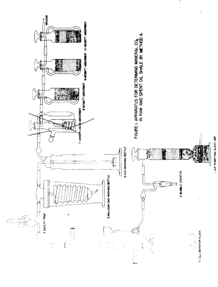
Tho apparatus used is shawn in figure 1 and consists of units numberod as followss
1. Air-purifying jar filled with a sootion of magnesium perQhlorato to remove water and a soction of Caroxite (or Ascarite) to
romovo CO2- Tho jar servos to purify the air used to flush
the apparatus. .
2. Bubblo countor fillod with wator tor a guido in rogulating tho flow of air during tho flushing operation.
CO2 liberation-flask assambly wh~ch is constructed to allow aoid to be added to the liborat ion flask.
4. Safety trap.
5. ~lligan-typo gas-washing bottle to removo hydrogon sulfide.
This bottle is charged with a solution of 20 gm. cadmium chloride por 100 ml. of 0.5 normal H2S04
6. Gas-washing bottle equippod with frittod-glass disk and chargod with the samo solutio~ as bottle 5.
7. Vanier liquid absorbor charged with concentrated H2S04 to remove the major portion of water vapor from the evolved gases.
f
8. Nesbitt-type absorber Charged with magnesium perchlorate to remove all tracos of water.
9. Nesbitt-type absorber charged with Caroxite (or Ascarite) followed by a thin layor of magnesium perchlorate. The small amount of magnesium perchlorate is present to absorb traces
of water whiCh may result fram the reaction of the Caroxito and CO2•
10. Nosbitt-typo absorber Charged with a layer of: magnesium porChlorate and a layer of Caroxito (or Asoarite) to remove H20 or CO from any baok surgo of air caused by the failuro2
of tho Vacuum system. PROCEDURE
A 1.0000-gram sample of the material to bo tested is transferred to tho liberation flask, This is conveniently done by weighing the sample in a small poroolain crucible (No. 000 Coors) and carefully lowering the crucible end sample into the liberation flask containing 50 mI. of freshly distilled water. Tho flask is fitted to the co~denser,
and water is circulated to condense mest of the moisture passing off with tho gas. The CO2 absorber is removed fram the absorption train
and placed in tho balanco for weighing. A glass tube is placed across the space left by the absorber and bridges this position during the flushing period. Suction is applied, ~nd the r~te of flow of air is maintained such that flushing of the systom is completed in a period of 15 minutes. During the last five minutes of this flushing period, the absorption bottlo is opened briefly to the atmosphere te attain atmospheric pressure, then carefully weighed. In this weighing, another absorber of similar design and approximate weight is used as a counter poisee Tho weighed absorber is now returned to its proper place in the
absorption train and a slight vacuum placed on the systemJ 15 mI. of concentrat'ed nCL is introducod into the system taking care to-avoid the entrance of air. Tho flesk is heated, and the liquid is boilod until till of the CO
2 has boen liberated. (This is indicated by almost complete cessation of bubbling in the gas-washing bottlos.) The three way valve on the liberation flask is then turnod to flush the system with purified air for 30 minutes. After this period the heating is discontinuod, tho liboration flask vonted by turning the stopc-ook, and the absorber is removed and weighed. Caution. bofore making another nnnlysis, the acid inlet tube should be thoroughly washed with distilled wator to remove all traces of acid.
Blank determinations should bo made periedically in tho manner desoribed above using all the reagents but omitting the sc.mple, and tho corroction thus obtainod applied to the analyses of unknown samples. The correction is gvncro.lly small, but it is necessary for highest accuracy.
\ ) FIG~ I AIR I'VRIfYlNG GlASS JIUII ;, I: I I <=--'.
1
"*l.AJM~t
II
I i l . . I !i. IooIIU..JGAH GAS WASHING IIOTIU ~I
J&
6 GAS WASHING !IOTTLE ~ l APPARATUS FOR DETERMING MINERAl. Co, IN RAW AND SPENT OIL SHALE BY METHOO A. ~ 3 Co, LIBERATION FLASK ".. \J-I...
IJ.I ICAI.CULAT IONS
The following data are neoessary for calculating the percent
or
CO2 and mineral carbonate (C03) in raw and spent oil shalerWeight of conditioned absorber
+
absorbed CO2 Woight of conditioned absorberDifforence
=
weight of absorbod CO2 Blank obtained by direct determinationDifforence
=
correoted weight of CO2
Peroent CO
=
£2rroctod weight of C02 x 1002 Woi~ht
of
SmnplePeroent mineral cnrbonate : Correoted weisht of CO~ x 1.3636 x 100
We ight of wnp le PRECISION AND ACCURACY
By this method an oxperienced analyst should obtain duplicnte rosults varying not more than
+
0.06% tram the average, and duplicate determinations by two or more nnalysu should not vary more than+
0.08%. This represonts n max1mullJ"orror of not more than 0.6% onshales having a CO2 eontent of 16%. A highor aocuraoy may be obtained when neoessary by increasing the sample weight.
PRECAUTIONS AND ADAPTATIONS
Incorrect weighing of the absorption bulb is the most likely cause of error. Therefore, a count~r poise of similar design should be used in weighing to minimize air buoyancy effeots, and both waigh ing$
Qt
a given absorption bulb should be made at tho same room temperuture. The acid inlet tube should be thoroughly washed with distilled-water to remove all traces of acid before a new flask isfitted to thQ condensor,
This method is satisfacto~ for the dotermination of mineral carbonato of raw and spent shalo and may also be usoful for CO2
determinations of othor substances, particularly thoso which contatn mineral sulfides.
Method B. Volumetric Determination' of COal in Raw and Spent Shales
SCOPE
This proceduro is applicable to tho dotermination of CO in shales when a rapid and fairly accurate determination is required. 2It is espacially useful when considerable timo elapsos between series of
A-3-4
determinations sinoe the appar~tus Oan stand assembled for a long period
ot
time and yet require very little oleaning and other prepura~tion to make a series of' determinations.
Tho principle or this method is essentially tho same as for. the one desoribed in "Soott's Standard Methods of Chemioal Analysis.1t
(1) Two main variations ure, (1) a solution of HgC12 is used to wet the shale. bef'ore the addition of aoid, and (2) a dry standard lime sample is used to determine tho faotor used in the oalculations.
The HgC12 is necessary to preoipitato the sulfur from the H.2S that is liberated during tho aoid treatment so that it will not De determined as C02_
The method oonsists of' the following general stops: (1)
introduoe the shale sample into a gas tight system, (2) troat the sample with HC1, (3) measure tho total gas in tho system, (4) remove tho liborated CO2 by absorption in strong oaustio solution, (5)
measure remaining gas, and (6) oompare the volume of CO2 gas liberated from the shale sample with the volume of CO2 gas liberated from a standard 1ime sample.
APPARATUS
The attaohed figure illustrates tho apparatus used. It oonsists ot a Prooision Universal }jodel Fi slior Gas Measuring Unit with a valve bubbler gas absorption pipette filled with KOH solution. The two units are mounted on a Fisher.' fr£'Jno support unit.
Stopoooks A, B, e, and D are straight 3-way stopcooks as furnished with tho apparntus. Stopcooks E and F arc straight l""Way stopcooks whioh oomo on tho soparntory funnels. Separatory funnel H is used as a conoentrated HCl supply tunnel to eliminate unneoessary handling of the acid. Sepnratory tunno 1 J is used to introduoe the Hel and water into tho reaotion test tube.
A test tuboof approximately 50 ml. oapaoity is used to hold the shale sample during the acid treutment, and a reflux condenser is used to condense the water boilod orf during the hoating and return it to the test tube. It is not nooessary to ho.vo water running through. the
condenser but it neodonly be filled with water.
It is nooessary to have the bottom of the reflux oondenser extend only through the rubber stopper and not extend beyond. This is so that no gas pocket will ooour in tho top of tho tost tube. Tho oapaoity or the system from tho bottom of tho roflux oondonser to stopoook A should bo kept as small as possible and yet largo enough to nllow tho reflux oondons.or to return the oondonsed water to the test tube. This volume should bo approxim~tely 10 mI.
Tho delivery tube below stopoook F on tho soparatory funnol J
should be capillary tubing so that no gas will be trapped within the tubing.
A-3-5
-The uso of aoidified water with methyl red indioator has been found very satisfaotory for use in the leveling bulb and measuring burette; h~Never, for greator aocuraoy an acidified saturated solution
of Na2B04 or NnCl is reoommended. PROCEDURE!!
y
The description of the neoessary stopoock manipulations will, in general, bo omitted, sinoe that desoription becomes quite involvod and it is thought toot tho tn.'1.nipulations are self evident to the person making the determination.Weigh into the test tube a s&mple oapable of liberating approxi mately 50 oc. of CO2 gas, and add a pieoe of iron wire or filings larger than a pin head. Wet the shale with one drop of a 10 peroent aerosol solution and 5 to 10 00.
or
a 5 peroent HgC12 solution. Atterthe semple is thoroughly wetted., the total volume is made up to 25 mI. Raise the level of the KOH in the gas absorption pipette to the oapillary tubing, level the water oolumDB in the manometer, and fill ,the measuring burette with water from the leveling bulb.
Close stopoook A and open stopoook F and plaoe the test tube with the semple into position. Close F, open,4, eu::u:1 lower the leveling bulb to the bottom, of the_ stand. .Add 7 to 10 00. of oonoentrated HCl from separatory funnel H to separatory funnel
J,
then let 5 00. of the aoid fran separatory funnel J drop slowly into the test tube and close stopcock F.Fill separatory funnel J nearly full of distilled water and as soon as the action in the test tube has subsided somewhat apply a small flame to the test tube and heat to boiling. Continue to boil for at least 2 minutes before removing the flame.
Atter the flame is removed,open stopoook F and lower the leveling bulb suffic~ont1y to fill tho reflux oondenser and the attaohed
oapillary tubing with water. Close stopoock A and raise the leveling bulb until the level
or
the water in it is the same a~ the level of the water in the gas measuring burette; then adjust the pressuretn
-the gas measuring burette to the some pressure o.s is in the compensatingburette by raising or loworing tho leveling bulb as needed.
Read and rooord the total volume
or
gas in the measuring burette.By the proper manipulation of -stopoocks B and C and by raising and lowering the leveling bulb run the entiro volume of gas in the measur ing burettc over into the absorption pipette and back again. Repeat at least twice. Atter the gc.s is returned to the measuring buratte for the last time adjust the pressure in it as before, then read and record tho volume of gas left in the measuring burette.
p
CALCULATIONS
The difference between the readings of the gas volumes, times a predetermined factor, divided by the weight of sample used, gives the peroent oarbonate CO2 in tho sample.
Porcent CO
=
factor x mI. COZ 2 wt. sampleThe factor is doterminod by using
a
standard limostono samplo of 0. known CO2 percentago in plaoe of a shalo sf~le and following exactly tho same procedure as described above. Argillacoous lime stone sample No. 10. from the National Buroau of Stnpdards has been found to be very satisfactory for this. purpose. The factor is then calculated according to the following f9rmulal
Faotor ~ ~!,_sl(lndard s(lI'l.l'le x p~~nt C02 in standard sam:ele ml. CO2 liberated
vfuen determining 0. nuw faotor stopoock D should be first opened momentarily to the atmosphere so that the pressure in the componsating burette is atmospheric. If it is nocessary to mnke 0. new factor doter mination, it is well to do so before tho serios of doterminations is
started for which the factor .is to bo used. PRECISION A1~ ~CCURACY
A reproducibility of
.t
1.0 percont of tho amount of CO2 prosent is possiblo and duplicato samples should check within these limits.The accuracy is vory nearly tho samo as the reproducibility. PRECAUTIOtJS
It is most necessary that tho gas measuring buretto bo absolutoly clean before usins the upparutuso Onco it is clean it will r~main so by leaving it filled with water from tho loveling bulb when the
apparatus is not being used.
__ Once the £luctor hus boen determined for f).ny series of determinations stopcock D should not be openod to the atmosphore. It is recommanded that- a periodic check dotermination of the factor be IlUlde.
REFERENCES
1. Soott, Wilfrod
W.;
Standard Methods of Chomical Analysis~D 1111111.0.0, CAPILLARY TUBING _ . J - + - -MANOMETER (H) 500ml FUNNEL I -l...l--+l--REFLUX CONDENSER (J) 100mi FUNNEL CAPILLARY DELIVERY TUSE 2111111,.170Illm, TEST TUBE -WATER JACKET
- GAS MEASURING BURETTE
COMPENSATING BURETTE
LEVELING BULB
ACIDIFIED WATER
- RUBBER TUBING
- '... ~
FIGURE 2 APPARATUS FOR THE VOLUMETRIC DETERMINATION OF CO2
IN SHALE BY METHOD B,
A-3-8
RRS-112
p
COMBUSTION AlIALYSIS FOR CARBON .MID HYDROGEN
IN ,OIL SHALE Alij) ITS PRODUCTS (Hethod A-4)
SCOPE
The determination of carbon and.hydrogen is essential in the complete analysis of oil shale; the accurate determination of these elements yields valuable information on raw shale, retorted shale, and the retorted oil and its fractions. The data fram these analyses may be used for a variety of purposes as evaluating oil shale and determining retorting efficienoy and the results of processes as hydrogenation, dehydrogenation, and cracking. The organic residue in spent shale can also be estimated from these analyses.
The determination
ot
carbon and hydrogen in organio compounds is generally oonsidered a difficult operation. This difficulty is increased greatly in determinatio~ on materials, suoh as raw oil shales, which oontain both organio and inorganic carbon and hydrogen. The method presented here was patterned after that given by Fischer (1), and was adapted to the determination of carbon and hydrogen in oil shale and its re~9rted products.APPARATUS
A diagram of the combustion apparatus 1s given in figure 1. A description of each component of the assembly follows. The numbers on the left margin refer to the items in figure 1.
'(1) Oxygen cyliIlder equipped with regulating valve to reduce the oxygen pressure to 3 to 4 psig followed by a needle valve to further control the flow rate.
(2) Three-way stopcock for establishing oxyge,n flow through the combustion train, or for venting the oxygen to the atmosphere.
(3) Variuble orifice manometer to indicate slight changes in the oxygen flaw~
(4) Absorption bulb containing drying agent.
(5) ~[ercury-filled pressure go.uge which also serves as 0.
relief valve in Case of oxcessive gas pressure.
(6) Vycor preheating and purifying tube, 0.8 inch (19 rom.) I.D., 1 inch (25 mm.) O.D. The lQngth of this tube is not oritical, but it must be sufficiently long to prevent overheating the Neoprene stoppers in eaoh end. Old
combustion tubos may be used.
(7) Preheating and purifying tub~ furnace with l2-inch heater section. A type 70 furnace made by Hevi Duty Electric Company has been found satisfactory. Suitable control should be provi~ed so that the furnaoe may be heated to a temperature of 8500C.
(8
&
9) Absorption bottles of the Nesbitt type. U Tubesmay
alsobe used for this purpose.
(10) Breech connoctor, regular size (1-3/8 inch socket) made by Fisoher Scientific Company.
(11) Vycor combustion tube, 0.8 inCh (19 rom.) I.D., 1.0 inch
(25
nm.)
O.D., 39.3 inches (1000nm.)
long. The fillingof the combustion tube is described under "Assembling and Conditioning the Combustion Train.1I
(12,13
&
Combustion furnaces similar to type 123 made by Central 14) Scientific Company. The three furnaoes are mounted on asingle frame with a rheostat below each furnace. Independ ent temperatures may be maintained with these rheostats. Tho lengths of the heater elements in furnaoe sections
K.
L,
and Mare4,
12, Ilnd 8 inohes, respeotivoly.(15 & 16) Absorption bottles of the Nesbitt type. Bottle 15 is the
H20 absorbor,bottle 16 is the CO2 absorber,
(17) Absorption bulb oontaining CO absorbent and Q dessioant.
2
This guard bottlo preve~s contamination of the absorber bottles by the atmosphere in case tho combustion of tho sample is too rapid. Rapid combustion may cause a partial vacuum and reverse the gas flow through the absorbors. (18) Bubble counter.
Materials and Reagents
c~per·PlUgs. Spirally wound plugs or copper screen wire are
insert~ in sevorlll positions in the combustion tubo. The mesh size
of tho soreon is not oritical, but 20-mcsh is commonly uBed. Tho plugs should be wound compactly and should fit the bore of the tube snugly. so that the gases flow through the plugs rather than around them.
Viator absorbent. "Dehydrite" (anhydrous magnesium ·porchlorato), a powerful dessicant, is recommended. "Indioating Drierite" is usod at the tops of the bottles to show whon the water absorbers need re· charging.
Carbon dioxide absorbent. "Caroxite", 8 to 20 mesh, an indicating CO2 absorbent (supplied by Eime~ Amend or the Fischer Scientific Company), is recommonded. "Ascllrito" may o.lso be used, but "Caroxite" is preferred because of the indicating feature.
~
riD
I~
c@
l@@?
I1
i@~,~
7~