Mälardalen University Press Licentiate Theses No. 224
RAISING ABSTRACTION OF TIMING ANALYSIS
THROUGH MODEL-DRIVEN ENGINEERING
Alessio Bucaioni
2015
School of Innovation, Design and Engineering
Mälardalen University Press Licentiate Theses
No. 224
RAISING ABSTRACTION OF TIMING ANALYSIS
THROUGH MODEL-DRIVEN ENGINEERING
Alessio Bucaioni
2015
Copyright © Alessio Bucaioni, 2015 ISBN 978-91-7485-245-5
ISSN 1651-9256
Printed by Mälardalen University, Västerås, Sweden
Abstract
The complexity of software running on vehicular embedded systems is con-stantly increasing and this negatively affects its development costs and time to market. One way to deal with these issues is to boost abstraction in the form of models to (i) ease the reasoning about the system architecture, (ii) automate certain stages of the development, (iii) early detect flaws in the system architec-ture through fundamental analysis and (iv) take appropriate countermeasures before the system is implemented.
Considering the importance of timing requirements in the design of soft-ware for vehicular embedded systems, in this licentiate thesis we leverage Model-Driven Engineering for realizing a semi-automatic approach which al-lows the developer to perform end-to-end delay timing analysis on design mod-els, without having to manually model timing elements and set their values.
The proposed approach, starting from a design model of an automotive software functionality, automatically generates a set of models enriched with timing elements whose values are set at generation time. End-to-end delay tim-ing analysis is run on the generated models and, based on the analysis results, the approach automatically selects the generated models which better meet a specific set of timing requirements.
Sammanfattning
Nuf¨ortiden finns inbyggda datorsystem i de flesta elektroniska och elektriska produkter. Allt ifr˚an str¨ombrytare och mikrov˚agsugnar till bilar och t˚ag ¨ar beroende av moderna inbyggda datorsystem. I fordonsindustrin, ¨okar st¨andigt antalet inbyggda system som ers¨atter hydrauliska och mekaniska delar som inte kan leverera moderna tj¨anster som kollisionsskydd och antisladdsystem. Samtidigt ¨okar komplexiteten av dessa datorsystem och deras mjukvara, och detta p˚averkar negativt utvecklingskostnader och tid. Ett s¨att att minska dessa problem ¨ar att anv¨anda abstraktioner i form av modeller f¨or att i) enklare resonera ¨over systemets arkitektur, ii) automatisera vissa utvecklingsfaser, iii) tidigt sp˚ara brister i systemets arkitektur genom grundl¨aggande analyser och iv) ˚atg¨arda brister innan systemet f¨ardigst¨alls.
I denna avhandling anv¨ander vi modelldriven utveckling f¨or att skapa en ny metod som f¨orenklar utvecklingen av inbyggda system f¨or fordon. Detta sker genom att utvecklaren beskriver systemet som en abstrakt arkitekturmod-ell som anv¨ands av metoden f¨or att automatiskt generera ett antal m¨ojliga konkreta modeller. End-to-end tidsanalys k¨ors p˚a de genererade modellerna och analysresultat anv¨ands av metoden f¨or att automatiskt v¨alja bland de gener-erade modellerna dem som uppfyller de uppsatta tidskraven b¨ast.
Acknowledgements
First and foremost, my utmost gratitude to my supervisors Mikael Sj¨odin, An-tonio Cicchetti and Federico Ciccozzi whose guidance is making this a possible and pleasant journey. They are mentors, colleagues and friends and they are helping me in becoming a better person before than a better researcher.
I would like to express my deepest gratitude to my “buddy” Saad Mubeen, who helped me in moving the first steps into the research world. We shared unforgettable moments and i could not ask for a better “buddy”.
I would like to thank Kurt-Lennart Lundb¨ack and all the people from Arcti-cus Systems AB for giving me the possibility to work in such a successful company without never interfere with my researches.
I would like to thank all the administrative staff, especially Carola Rytters-son and Susanne Fronn˚a for making “paper-work” easier.
I would like to thank my friends and colleagues at the department for all the good and funny moments and for the inspiration they give me each day.
I will never thank enough my family for supporting me, even financially, and for never discussing my decisions, even when these brought me far away from their life. Without you, i would be lost.
I would like to thank all my friends, both in Italy and Sweden, for standing by my side and for never making me feel alone. Especially, i would like to thank Manuel, Mirco and Giada for having brought some joy in a difficult period of my life.
I would like to thank my grandpas Vincenzo and Terzilio, my aunts Ines and Nunziata and my uncle Pasquale for watching over me.
Last, but not least i would like to thank the One above us all, God, for answering my prayers and for giving me the strength to never throw in the towel.
Alessio Bucaioni V¨aster˚as, December, 2015
List of Publications
Publications Included in this Licentiate Thesis
1Paper A – A Metamodel for the Rubus Component Model: Exten-sions for Timing and Model Transformation from EAST-ADL,
Ales-sio Bucaioni, Saad Mubeen, Federico Ciccozzi, Antonio Cicchetti, Mi-kael Sj¨odin, Conditionally accepted at the Journal of Systems and
Soft-ware (JSS).
Paper B – Exploring Timing Model Extractions at EAST-ADL De-sign -level Using Model Transformations, Alessio Bucaioni, Saad
Mu-been, Antonio Cicchetti, Mikael Sj¨odin, IEEE 12th International
Confer-ence on Information Technology: New Generations (ITNG), Las Vegas, Nevada (USA), April, 2015.
Paper C – Raising Abstraction in Timing Analysis for Vehicular Em-bedded Systems through Model-Driven Engineering, Alessio
Buca-ioni, Doctoral Symposium at Software Technologies: Applications and
Foundations (STAF), L’Aquila, Italy, July, 2015. Best paper award. Paper D – Anticipating Implementation-Level Timing Analysis for Driving Design-Level Decisions in EAST-ADL, Alessio Bucaioni,
An-tonio Cicchetti, Federico Ciccozzi, Romina Eramo, Saad Mubeen, Mi-kael Sj¨odin, 1st International Workshop on Modelling in Automotive
Software Engineering (MASE) at ACM/IEEE 18th International Con-ference on Model Driven Engineering Languages and Systems (Models), Ottawa, Canada, September, 2015.
1The included publications are reformatted to comply with the licentiate thesis printing format
viii
Related Publications not Included in this Thesis
Comparative Evaluation of Timing Model Extraction Methodolo-gies at EAST-ADL Design Level, Alessio Bucaioni, Saad Mubeen,
Fed-erico Ciccozzi, Antonio Cicchetti, FedFed-erico Ciccozzi, Mikael Sj¨odin,
IEEE 12th International Conference on Embedded Software and Sys-tems (ICESS), New York, New York, August, 2015.
Towards a metamodel for the Rubus Component Model, Alessio
Bu-caioni, Antonio Cicchetti, Mikael Sj¨odin, 1st International Workshop on
Model-Driven Engineering for Component-Based Software Systems at ACM/IEEE 17th International Conference on Model Driven Engineering Languages and Systems (Models), Valencia, Spain, September, 2014. OSLC Tool Integration and Systems Engineering - The Relationship Between The Two Worlds, Mehrdad Saadatmand, Alessio Bucaioni, 40th Euromicro Conference on Software Engineering and Advanced Ap-plications, Verona, August, 2014.
Demonstrator for modeling and development of component-based distributed real-time systems with Rubus-ICE, Alessio Bucaioni, Saad
Mubeen, John Lundb¨ack, Kurt-Lennart Lundb¨ack, Jukka M¨aki-Turja, Mikael Sj¨odin, Open Demo Session of Real-Time Systems (RTSS@Work
) at Real Time Systems Symposium (RTSS), Vancouver, Canada, De-cember, 2013.
Other Publications
Understanding bidirectional transformations with TGGs and JTL,
Alessio Bucaioni, Romina Eramo, 2nd International Workshop on
Bidi-rectional Transformations (BX) at European Joint Conferences on The-ory and Practice of Software (ETAPS), Roma, Italy, March, 2013. A Model-Based Testing Framework for Automotive Embedded Sys-tems, Raluca Marinescu, Mehrdad Saadatmand, Alessio Bucaioni,
Cri-stina Seceleanu, Paul Pettersson, 40th Euromicro Conference on
Soft-ware Engineering and Advanced Applications, Verona, August, 2014.
ix
EAST-ADL Tailored Testing: From System Models to Executable Test Cases, Raluca Marinescu, Mehrdad Saadatmand, Cristina
Sece-leanu, Paul Pettersson, Alessio Bucaioni, MRTC Report
xi
xi
Contents
I
Thesis
1
1 Introduction 3 1.1 Thesis Contribution . . . 5 1.2 Terminology . . . 6 1.3 Thesis Outline . . . 7 2 Research Plan 9 2.1 Research Goal . . . 9 2.2 Research Challenges . . . 10 2.3 Research Contributions . . . 11 2.4 Papers Contribution . . . 16 2.4.1 Paper A . . . 16 2.4.2 Paper B . . . 17 2.4.3 Paper C . . . 17 2.4.4 Paper D . . . 18 2.5 Research Methodology . . . 193 Conclusions and Future Works 21 Bibliography 23
II
Included Papers
25
4 Paper A: A Metamodel for the Rubus Component Model: Extensions for Timing and Model Transformation from EAST-ADL 27 4.1 Introduction . . . 29Contents
I
Thesis
1
1 Introduction 3 1.1 Thesis Contribution . . . 5 1.2 Terminology . . . 6 1.3 Thesis Outline . . . 7 2 Research Plan 9 2.1 Research Goal . . . 9 2.2 Research Challenges . . . 10 2.3 Research Contributions . . . 11 2.4 Papers Contribution . . . 16 2.4.1 Paper A . . . 16 2.4.2 Paper B . . . 17 2.4.3 Paper C . . . 17 2.4.4 Paper D . . . 18 2.5 Research Methodology . . . 193 Conclusions and Future Works 21 Bibliography 23
II
Included Papers
25
4 Paper A: A Metamodel for the Rubus Component Model: Extensions for Timing and Model Transformation from EAST-ADL 27 4.1 Introduction . . . 29xiv Contents
4.2 Background and related work . . . 31
4.2.1 MDE and CBSE in the Automotive Domain . . . 31
4.2.2 End-to-end timing models and analyses . . . 34
4.2.3 Paper contributions . . . 36
4.3 Providing a metamodel for RCM . . . 37
4.4 DL2RCM model transformation . . . 41
4.5 Application to the steer-by-wire system . . . 48
4.6 Evaluation and discussion . . . 52
4.7 Conclusions and future work . . . 56
Bibliography . . . 57
5 Paper B: Exploring Timing Model Extractions at EAST-ADL Design-level Using Model Transformations 61 5.1 Introduction . . . 63
5.1.1 Paper Contribution . . . 63
5.1.2 Relation with Authors’ Previous Works . . . 64
5.2 Background and Related Works . . . 65
5.2.1 EAST-ADL Development Methodology . . . 65
5.2.2 The Rubus Component Model (RCM) . . . 66
5.2.3 End-to-end Timing Models and Analyses . . . 67
5.2.4 Model Driven Engineering (MDE) and Janus Transfor-mation Language (JTL) . . . 68
5.2.5 MDE for DSE . . . 69
5.3 Problem Statement . . . 69
5.4 Proposed Solution and Methodology . . . 71
5.4.1 Transformation phase . . . 73
5.4.2 Timing analysis phase . . . 73
5.4.3 Proof of concept . . . 75
5.5 Conclusion . . . 75
Bibliography . . . 77
6 Paper C: Raising Abstraction in Timing Analysis for Vehicular Embedded Systems through Model-Driven Engineering 79 6.1 Introduction . . . 81 6.1.1 Context . . . 81 6.1.2 Paper Outline . . . 84 6.2 Problem Formulation . . . 84 Contents xv 6.2.1 Research Goal . . . 84 6.2.2 Research Challenges . . . 85
6.3 Proposed Solution and Intended Contributions . . . 86
6.4 Preliminary Work and Current Status . . . 88
6.5 Validation . . . 89
6.6 Related Work . . . 89
6.6.1 Modeling Languages for Vehicular Embedded Systems 89 6.6.2 Model-Driven Engineering for Vehicular Embedded Systems . . . 91
Bibliography . . . 93
7 Paper D: Anticipating Implementation-Level Timing Analysis for Driving De-sign -Level Decisions in EAST-ADL 97 7.1 Introduction . . . 99
7.2 Related Work . . . 100
7.3 A Running Example: the Steer-by-wire System . . . 101
7.4 Applying the methodology . . . 102
7.4.1 Transformation Phase . . . 103
7.4.2 End-to-end Delay Analysis Phase . . . 107
7.4.3 Filtering and Propagation Phases . . . 108
7.5 Discussion . . . 109
7.6 Conclusion . . . 110
xiv Contents
4.2 Background and related work . . . 31
4.2.1 MDE and CBSE in the Automotive Domain . . . 31
4.2.2 End-to-end timing models and analyses . . . 34
4.2.3 Paper contributions . . . 36
4.3 Providing a metamodel for RCM . . . 37
4.4 DL2RCM model transformation . . . 41
4.5 Application to the steer-by-wire system . . . 48
4.6 Evaluation and discussion . . . 52
4.7 Conclusions and future work . . . 56
Bibliography . . . 57
5 Paper B: Exploring Timing Model Extractions at EAST-ADL Design-level Using Model Transformations 61 5.1 Introduction . . . 63
5.1.1 Paper Contribution . . . 63
5.1.2 Relation with Authors’ Previous Works . . . 64
5.2 Background and Related Works . . . 65
5.2.1 EAST-ADL Development Methodology . . . 65
5.2.2 The Rubus Component Model (RCM) . . . 66
5.2.3 End-to-end Timing Models and Analyses . . . 67
5.2.4 Model Driven Engineering (MDE) and Janus Transfor-mation Language (JTL) . . . 68
5.2.5 MDE for DSE . . . 69
5.3 Problem Statement . . . 69
5.4 Proposed Solution and Methodology . . . 71
5.4.1 Transformation phase . . . 73
5.4.2 Timing analysis phase . . . 73
5.4.3 Proof of concept . . . 75
5.5 Conclusion . . . 75
Bibliography . . . 77
6 Paper C: Raising Abstraction in Timing Analysis for Vehicular Embedded Systems through Model-Driven Engineering 79 6.1 Introduction . . . 81 6.1.1 Context . . . 81 6.1.2 Paper Outline . . . 84 6.2 Problem Formulation . . . 84 Contents xv 6.2.1 Research Goal . . . 84 6.2.2 Research Challenges . . . 85
6.3 Proposed Solution and Intended Contributions . . . 86
6.4 Preliminary Work and Current Status . . . 88
6.5 Validation . . . 89
6.6 Related Work . . . 89
6.6.1 Modeling Languages for Vehicular Embedded Systems 89 6.6.2 Model-Driven Engineering for Vehicular Embedded Systems . . . 91
Bibliography . . . 93
7 Paper D: Anticipating Implementation-Level Timing Analysis for Driving De-sign -Level Decisions in EAST-ADL 97 7.1 Introduction . . . 99
7.2 Related Work . . . 100
7.3 A Running Example: the Steer-by-wire System . . . 101
7.4 Applying the methodology . . . 102
7.4.1 Transformation Phase . . . 103
7.4.2 End-to-end Delay Analysis Phase . . . 107
7.4.3 Filtering and Propagation Phases . . . 108
7.5 Discussion . . . 109
7.6 Conclusion . . . 110
I
Thesis
I
Thesis
Chapter 1
Introduction
Nowadays, embedded systems play a prevailing role in everyday life as they are widely employed in most electronic and electrical products, from microwave ovens to trains and cars. In the specific case of the automotive domain, embed-ded systems replace many of the hydraulic and mechanical parts of a vehicle, improving the driving experience, the comfort of the passengers and the safety of the vehicle. The growing complexity of software running on embedded systems results in an increasing complexity of its development, which in turn negatively affects the development costs and time to market [1].
The software engineering community has agreed on three instruments when dealing with the increasing complexity of software and its development: i)
abstraction, ii) separation of concerns and iii) automation. In the midst of
the many methodologies advocating these three instruments when developing software systems, Model-Driven Engineering (MDE) has progressively gained recognition and industrial attention in the last 15 years [2].
MDE is a paradigm which aims at raising the level of abstraction of soft-ware development by shifting the focus from coding to modeling activities. In this context, models and model manipulations are promoted as first-class citizens. A model represents an abstraction of the software system, from a par-ticular point of view [3]. Models promote separation of concerns by describing the software system by means of different models each of which highlight-ing different concerns correspondhighlight-ing to different views. The set of rules and constraints for the construction of valid models are specified in the so-called
metamodel [3]. The relation between a model and its metamodel is called
con-formance [3]. According to the MDE paradigm, a software system is developed
4 Chapter 1. Introduction
by means of model manipulations, where abstract models are refined into more detailed ones, until code is automatically generated. Model manipulations are performed by means of model transformations [4] which automatically trans-late a source model into a target model while ensuring their conformance to their respective metamodels.
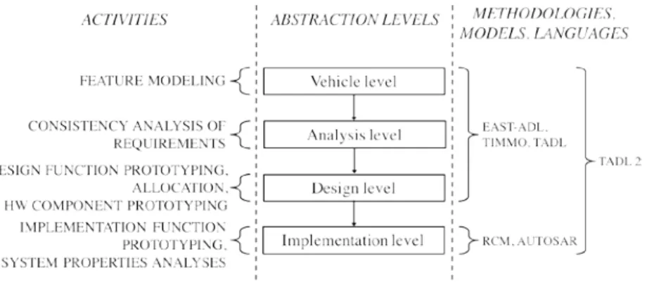
In the automotive domain, the adoption of MDE resulted in the standard-ization of an architectural description language, EAST-ADL [5], which is used for modeling product-lines of vehicular embedded systems. EAST-ADL pro-poses a view over the software development process composed by four differ-ent abstraction levels, which implicitly ensure separation of concerns through the different engineering phases. Each abstraction level is described by means of metamodeling constructs and aims at hiding unnecessary information from higher abstraction levels. EAST-ADL defines a set of activities to perform for each abstraction level, based on the expressible concepts. Figure 1.1 shows the EAST-ADL abstraction levels together with the related languages and activi-ties.
Figure 1.1: EAST-ADL Abstraction Levels Together With The Related Lan-guages and Activities
The highest abstraction level is represented by the vehicle level, which cap-tures information regarding the system’s functionality. At the analysis level, by using formal notations, vehicle functions are expressed in terms of behav-iors and interfaces. Yet, design and implementation details are omitted. At this stage, high level analysis for consistency checking of the requirements can be performed. At the design level, analysis-level artifacts are refined with design-oriented details, such as software, middleware and hardware separation as well
1.1 Thesis Contribution 5
as allocation of software. At the implementation level, artifacts introduced at the design level are refined with implementation details for enabling system properties analyses, e.g., end-to-end delay timing analysis. At this stage, com-ponent models1 (e.g., Rubus Component Model (RCM) or AUTOSAR) are
used to model the system in terms of components and their interactions. The output of this level is a complete software architecture which can be used for code generation.
In this thesis, we consider RCM as the language for the implementation level [7]. RCM is a component model for the development of resource-constrai-ned embedded real-time software systems. It is developed by Arcticus Systems AB in collaboration with M¨alardalen University and it is currently adopted by several international companies, e.g., as alternative to AUTOSAR. Consider-ing the importance of timConsider-ing analysis for vehicular embedded systems [8] [9], RCM implements state-of-the-art end-to-end delay timing analysis [10] [11]. End-to-end delay timing analysis is used for providing evidence that behav-iors of the software system meet a specific set of timing requirements. Within EAST-ADL, end-to-end delay timing analysis gives meaningful results only if run on implementation models which are currently manually defined starting from design models. Unfortunately, when dealing with systems of industrial size, this manual process becomes soon overwhelming, leading to the creation of a very limited subset of implementation models only . By having automation support among the different EAST-ADL abstraction levels, and in our specific case between EAST-ADL design and implementation levels, it would be pos-sible to enable swift transitions avoiding error-prone and tedious manual activ-ities (model manipulations). Also, it would be possible to leverage end-to-end delay timing analysis results for driving design decisions avoiding late discov-eries of unacceptable quality of service with respect to timing requirements [8].
1.1 Thesis Contribution
In this licentiate thesis, we leverage MDE for realizing a semi-automatic ap-proach which allows the developer to perform timing analysis on EAST-ADL design models without having to manually specify their timing elements. More precisely, starting from an EAST-ADL design model of an automotive software 1A software component is a software element which i) conforms to a component model, ii) can
be deployed independently and iii) can be composed according to a composition standard [6]. A
component model specifies i) the properties of software components and ii) how software
4 Chapter 1. Introduction
by means of model manipulations, where abstract models are refined into more detailed ones, until code is automatically generated. Model manipulations are performed by means of model transformations [4] which automatically trans-late a source model into a target model while ensuring their conformance to their respective metamodels.
In the automotive domain, the adoption of MDE resulted in the standard-ization of an architectural description language, EAST-ADL [5], which is used for modeling product-lines of vehicular embedded systems. EAST-ADL pro-poses a view over the software development process composed by four differ-ent abstraction levels, which implicitly ensure separation of concerns through the different engineering phases. Each abstraction level is described by means of metamodeling constructs and aims at hiding unnecessary information from higher abstraction levels. EAST-ADL defines a set of activities to perform for each abstraction level, based on the expressible concepts. Figure 1.1 shows the EAST-ADL abstraction levels together with the related languages and activi-ties.
Figure 1.1: EAST-ADL Abstraction Levels Together With The Related Lan-guages and Activities
The highest abstraction level is represented by the vehicle level, which cap-tures information regarding the system’s functionality. At the analysis level, by using formal notations, vehicle functions are expressed in terms of behav-iors and interfaces. Yet, design and implementation details are omitted. At this stage, high level analysis for consistency checking of the requirements can be performed. At the design level, analysis-level artifacts are refined with design-oriented details, such as software, middleware and hardware separation as well
1.1 Thesis Contribution 5
as allocation of software. At the implementation level, artifacts introduced at the design level are refined with implementation details for enabling system properties analyses, e.g., end-to-end delay timing analysis. At this stage, com-ponent models1 (e.g., Rubus Component Model (RCM) or AUTOSAR) are
used to model the system in terms of components and their interactions. The output of this level is a complete software architecture which can be used for code generation.
In this thesis, we consider RCM as the language for the implementation level [7]. RCM is a component model for the development of resource-constrai-ned embedded real-time software systems. It is developed by Arcticus Systems AB in collaboration with M¨alardalen University and it is currently adopted by several international companies, e.g., as alternative to AUTOSAR. Consider-ing the importance of timConsider-ing analysis for vehicular embedded systems [8] [9], RCM implements state-of-the-art end-to-end delay timing analysis [10] [11]. End-to-end delay timing analysis is used for providing evidence that behav-iors of the software system meet a specific set of timing requirements. Within EAST-ADL, end-to-end delay timing analysis gives meaningful results only if run on implementation models which are currently manually defined starting from design models. Unfortunately, when dealing with systems of industrial size, this manual process becomes soon overwhelming, leading to the creation of a very limited subset of implementation models only . By having automation support among the different EAST-ADL abstraction levels, and in our specific case between EAST-ADL design and implementation levels, it would be pos-sible to enable swift transitions avoiding error-prone and tedious manual activ-ities (model manipulations). Also, it would be possible to leverage end-to-end delay timing analysis results for driving design decisions avoiding late discov-eries of unacceptable quality of service with respect to timing requirements [8].
1.1 Thesis Contribution
In this licentiate thesis, we leverage MDE for realizing a semi-automatic ap-proach which allows the developer to perform timing analysis on EAST-ADL design models without having to manually specify their timing elements. More precisely, starting from an EAST-ADL design model of an automotive software 1A software component is a software element which i) conforms to a component model, ii) can
be deployed independently and iii) can be composed according to a composition standard [6]. A
component model specifies i) the properties of software components and ii) how software
6 Chapter 1. Introduction
functionality, the proposed approach automatically generates a set of RCM models enriched with timing elements. End-to-end delay timing analysis is run on the generated RCM implementation models and, based on the results, the approach supports the selection of the generated RCM implementation model (or set of models) which better meets a specific set of timing requirements. To this end, the following contributions are identified:
1. RCM metamodel. Model transformations are required for achieving a full-fledged MDE approach for leveraging end-to-end delay timing anal-ysis at design level. Moreover, model transformations are specified on the involved metamodels. While EAST-ADL provides a metamodel def-inition for the design level, RCM has not been described by metamodel-ing means. This contribution provides a metamodel definition for RCM. 2. Model transformation between EAST-ADL design level metamodel and
RCM metamodel. This contribution allows the automatic translation
from an EAST-ADL design model into a set of meaningful RCM im-plementation models that can be used as input for running end-to-end delay timing analysis.
3. Selection mechanism. Based on end-to-end delay timing analysis re-sults, this contribution supports the selection of the RCM implementa-tion model (or set of models) which better meets a specific, non-empty set of timing requirements.
1.2 Terminology
In this section we introduce the terms that we use in the remainder of this licentiate thesis.
• End-to-end delay timing analysis. Schedulability analyses are a priori
analysis techniques used for ensuring that the software system meets its timing requirements. End-to-end delay timing analysis are well-establish-ed schwell-establish-edulability analyses which calculate upper bounds on the response time and delays of event chains distributed over several nodes or in the system. We will refer to end-to-end delay timing analysis simply as
tim-ing analysis.
• EAST-ADL design level. We will refer to EAST-ADL design level simply
as design level.
1.3 Thesis Outline 7
• EAST-ADL implementation level. We will refer to EAST-ADL implemen-tation level simply as implemenimplemen-tation level.
• EAST-ADL design level model. We will refer to EAST-ADL design level model simply as design model.
• EAST-ADL implementation level model. We will refer to EAST-ADL im-plementation level model simply as imim-plementation model.
• RCM implementation model. Different component models can be used
at the implementation level. As aforesaid, we decided to use RCM as the target language for the implementation level. With the term RCM
imple-mentation model we refer to a RCM model used at the impleimple-mentation
level.
• Timing requirement. We will refer to timing requirement as the required
timing performance specified on the vehicle functionality. A typical ex-ample would be: “the time between the request from the driver and the response of the physical system shall be lower than 10 milliseconds”.
• Timing property and timing value. Timing property is a property which
concerns the timing behavior of the software. A typical example of a timing property is the worst-case execution time of a function. Timing
value is the actual value of a timing property.
• Timing element. We refer to timing element as a modeling element which
represents a timing property or requirement.
• Non-bijective model transformation. A non-bijective model transforma-tion is a model transformatransforma-tion that translates a single source model into
multiple target models.
1.3 Thesis Outline
The remainder of this thesis is organized as follows. Chapter 2 describes the re-search plan in terms of rere-search goals, challenges and contributions. Chapter 3 discusses conclusions and future directions. The second part of the thesis con-sists of Chapter 4 through Chapter 7 and describes the research contributions in terms of research publications.
Chapter 2
Research Plan
This chapter discusses the adopted research plan in terms of research goal, research challenges (RCs), research methodology and research contributions (RCOs).
2.1 Research Goal
Timing requirements are crucial in the design of the software running on vehic-ular embedded systems [9] [8]. Timing analysis is a primary means by which timing requirements are verified. However, design decisions are usually not driven by timing analysis results as timing analysis is usually performed af-ter the design activities [12]. To this end, we believe that anticipating timing analysis at design level can mitigate software development issues (e.g., cost, time-to-market) as it would avoid late discoveries (i.e., during the testing ac-tivities) that the system delivers services of unacceptable quality with respect to timing [10] [8]. Within an EAST-ADL based methodology, the way towards early timing analysis is hampered by the weak linkage between the modeling language used at the implementation level (where timing analysis is usually performed) and the language used at the design level.
The goal of this research work is to enable timing analysis at design level for supporting design decisions. More specifically, we aim at providing an approach which gives automation means for seamlessly linking design and im-plementation level.
10 Chapter 2. Research Plan
2.2 Research Challenges
Considering the research goal, the following RCs have been formulated and used as main drivers for this research work.
RC 1. Definition of a metamodel for RCM.
While EAST-ADL does not fully embrace the MDE paradigm, it still provides metamodel definitions for the languages adopted at each abstraction level. Con-sequently, MDE seems to be the natural choice for automating an EAST-ADL based methodology.
According to the MDE paradigm, metamodels and model transformations are crucial for providing automation within the software development: the for-mer serves for regulating the specification of models while the latter for au-tomating their manipulations. In particular, it is very beneficial that all the modeling languages involved in the development process are provided with a metamodel definition. Considering that we want to provide automation be-tween the design and implementation levels, both the languages used at these levels should be provided with metamodel definitions. While for the design level a metamodel definition exists, our challenge is the definition of a meta-model for RCM, the language we use at the implementation level. In particular, the metamodel should be defined bearing in mind the following:
1. Backward compatibility: the metamodel should not hinder a migration of legacy RCM artifacts.
2. Maintainability: the metamodel should be easy to update and refine. RC 2. Definition of a mapping between EAST-ADL design level meta-model and RCM metameta-model.
Separation of concerns and abstraction are the pillars on which EAST-ADL relies and the EAST-ADL abstraction levels are designed to ensure these prin-ciples. Within EAST-ADL, timing analysis can only be performed at the imple-mentation level, since timing properties are not entailed in higher abstraction levels.
One way to leverage timing analysis results at design level is the defini-tion of a transparent and automatic process able to translate design models to implementation models, i.e., RCM implementation models, on which timing analysis can be performed. In fact, RCM implementation models contain tim-ing elements, e.g., clocks, control-flow ports, to mention a few, that can not be modeled at the design level. However, these elements represent variabil-ity points in the transition from design to implementation level, meaning that
2.3 Research Contributions 11
more than one RCM implementation model can be a valid translation of a given design model [13].
The challenge is to define and implement a semi-automatic translation able to produce a set of RCM implementation models for a given design model avoiding any manual, error-prone and time-consuming model manipulations. RC 3. Definition of a mechanism for the selection of the best RCM model for a specific, non empty set of timing requirements.
This represents the last step in the process of leveraging timing analysis at design level for enabling guided design decisions. After the RCM implemen-tation models are generated, timing analysis is run. Based on the timing anal-ysis results, the challenge is to define a mechanism able to select the RCM implementation model which better meets a specific, non empty set of timing requirements. The mechanism should be able to select multiple equally good RCM implementation models. Once the RCM implementation model (or set of models) is identified, its analysis results should be propagated back to design level and made accessible to the developer. In case no RCM implementation model satisfies the set of timing requirements, refinements on the design model are required.
2.3 Research Contributions
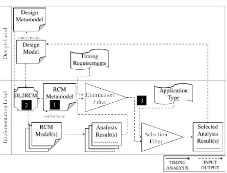
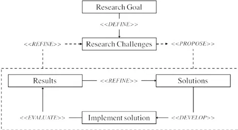
The main contribution of this licentiate thesis is the definition of an approach for seamlessly linking design and implementation level in order to enable tim-ing analysis at design level. This is needed to allow timtim-ing analysis results to drive design decisions. Figure 2.1 provides a graphical representation of the proposed approach.
Starting from a Design Model representing an automotive software func-tionality, the approach is able to generate a set of corresponding RCM Model(s). The generated set contains all the RCM Model(s) which are meaningful for the considered Timing Analysis. RCM Model(s) are equipped with timing ele-ments. While the generation of these elements is fully automated, their com-pletion with timing properties is entrusted to the developer. That is to say, the developer drives the automatic generation of all the meaningful combina-tions of timing elements by inserting timing properties, via configuration files, only once per element instead of having to manually edit all the generated RCM
Model(s). At this point, Timing Analysis is run on the generated RCM Model(s)
non-10 Chapter 2. Research Plan
2.2 Research Challenges
Considering the research goal, the following RCs have been formulated and used as main drivers for this research work.
RC 1. Definition of a metamodel for RCM.
While EAST-ADL does not fully embrace the MDE paradigm, it still provides metamodel definitions for the languages adopted at each abstraction level. Con-sequently, MDE seems to be the natural choice for automating an EAST-ADL based methodology.
According to the MDE paradigm, metamodels and model transformations are crucial for providing automation within the software development: the for-mer serves for regulating the specification of models while the latter for au-tomating their manipulations. In particular, it is very beneficial that all the modeling languages involved in the development process are provided with a metamodel definition. Considering that we want to provide automation be-tween the design and implementation levels, both the languages used at these levels should be provided with metamodel definitions. While for the design level a metamodel definition exists, our challenge is the definition of a meta-model for RCM, the language we use at the implementation level. In particular, the metamodel should be defined bearing in mind the following:
1. Backward compatibility: the metamodel should not hinder a migration of legacy RCM artifacts.
2. Maintainability: the metamodel should be easy to update and refine. RC 2. Definition of a mapping between EAST-ADL design level meta-model and RCM metameta-model.
Separation of concerns and abstraction are the pillars on which EAST-ADL relies and the EAST-ADL abstraction levels are designed to ensure these prin-ciples. Within EAST-ADL, timing analysis can only be performed at the imple-mentation level, since timing properties are not entailed in higher abstraction levels.
One way to leverage timing analysis results at design level is the defini-tion of a transparent and automatic process able to translate design models to implementation models, i.e., RCM implementation models, on which timing analysis can be performed. In fact, RCM implementation models contain tim-ing elements, e.g., clocks, control-flow ports, to mention a few, that can not be modeled at the design level. However, these elements represent variabil-ity points in the transition from design to implementation level, meaning that
2.3 Research Contributions 11
more than one RCM implementation model can be a valid translation of a given design model [13].
The challenge is to define and implement a semi-automatic translation able to produce a set of RCM implementation models for a given design model avoiding any manual, error-prone and time-consuming model manipulations. RC 3. Definition of a mechanism for the selection of the best RCM model for a specific, non empty set of timing requirements.
This represents the last step in the process of leveraging timing analysis at design level for enabling guided design decisions. After the RCM implemen-tation models are generated, timing analysis is run. Based on the timing anal-ysis results, the challenge is to define a mechanism able to select the RCM implementation model which better meets a specific, non empty set of timing requirements. The mechanism should be able to select multiple equally good RCM implementation models. Once the RCM implementation model (or set of models) is identified, its analysis results should be propagated back to design level and made accessible to the developer. In case no RCM implementation model satisfies the set of timing requirements, refinements on the design model are required.
2.3 Research Contributions
The main contribution of this licentiate thesis is the definition of an approach for seamlessly linking design and implementation level in order to enable tim-ing analysis at design level. This is needed to allow timtim-ing analysis results to drive design decisions. Figure 2.1 provides a graphical representation of the proposed approach.
Starting from a Design Model representing an automotive software func-tionality, the approach is able to generate a set of corresponding RCM Model(s). The generated set contains all the RCM Model(s) which are meaningful for the considered Timing Analysis. RCM Model(s) are equipped with timing ele-ments. While the generation of these elements is fully automated, their com-pletion with timing properties is entrusted to the developer. That is to say, the developer drives the automatic generation of all the meaningful combina-tions of timing elements by inserting timing properties, via configuration files, only once per element instead of having to manually edit all the generated RCM
Model(s). At this point, Timing Analysis is run on the generated RCM Model(s)
non-12 Chapter 2. Research Plan
Figure 2.1: Research Contributions
empty set of Timing Requirements and the RCM Model which better satisfies the Timing Requirements is selected; note that multiple RCM Models might be equally good and thereby selected. Eventually, the corresponding analysis re-sults, i.e., Selected Analysis Result(s), are propagated back to the developer by means of annotations to the design model. Figure 2.1 provides a breakdown of the main contribution in specific RCOs.
RCO 1 - RCM metamodel. This contribution, marked as 1 in Figure 2.1, provides a metamodel definition for RCM as the first step in the process of providing automation means. The RCM metamodel has been realized within the Eclipse Modeling Framework1 (EMF) as an EMF model, and it has been
defined with particular attention to backward compatibility and maintainability. In order to address the first goal, i.e., backward compatibility, we reverse-engineered the internal representation of RCM into the Rubus-ICE for polish-ing redundancies and optimizpolish-ing model traversals. This resulted in the
addi-1http://www.eclipse.org
2.3 Research Contributions 13
tion of 6 modeling elements (e.g., connectors) and the refinement of element hierarchies (e.g., ports and data element hierarchies). With respect to main-tainability, building-up the development environment on the RCM metamodel allows to separate the modeling elements from their rendering and features of the development environment.
RCO 2 - DL2RCM transformation. This contribution, marked with 2 in Figure 2.1, provides a model-to-model transformation between design models and RCM implementation models (DL2RCM).
The DL2RCM transformation has been implemented by means of a bidi-rectional model transformation language, namely Janus Transformation Lan-guage (JTL) [14]. JTL is a constraint-based bidirectional model transforma-tion language specifically tailored to support non-bijectivity by generating all the possible models, at once. JTL adopts a QVTr-like syntax [15], supports ob-ject pattern matching, and implicitly creates traces to record what occurs during the execution of a model transformation. The JTL implementation relies on the Answer Set Programming (ASP) [16], which is a declarative programming lan-guage based on the answer set (model) semantics of logic programming. The ASP solver, by means of a deductive process, finds and generates in a single execution all the possible models which are consistent with the transformation rules.
The DL2RCM transformation consists of 28 rules mapping design ele-ments to corresponding RCM implementation eleele-ments. The contribution bro-ught by the DL2RCM transformation is two-fold. On the one hand, it allows the automatic translation of EAST-ADL design models to RCM implementa-tion models. On the other hand, it is able to generate the set of all meaningful RCM implementation models for a given design model. That is to say, given the EAST-ADL design model depicted in Figure 2.2a and considering the gen-eration of clocks in the RCM implementation models, the DL2RCM transfor-mation produces 8 RCM implementation models each of which has a unique combination of clocks. 3 of the 8 possible models are depicted in Figure 2.2b. It is worth to note that JTL supports the specification of logic constraints which can be used for reducing the number of generated models and tailoring their generation for specific purposes. In the specific case of the DL2RCM transformation, we employed logic constraints for forcing the injectivity on the design elements not affected from the specified timing constraints. Paper A (Section 4) discusses an initial version of the transformation which produces one single RCM model from a design model. In Paper D (Section 7) we pro-vide an enhanced version which is able to generate all the meaningful RCM
12 Chapter 2. Research Plan
Figure 2.1: Research Contributions
empty set of Timing Requirements and the RCM Model which better satisfies the Timing Requirements is selected; note that multiple RCM Models might be equally good and thereby selected. Eventually, the corresponding analysis re-sults, i.e., Selected Analysis Result(s), are propagated back to the developer by means of annotations to the design model. Figure 2.1 provides a breakdown of the main contribution in specific RCOs.
RCO 1 - RCM metamodel. This contribution, marked as 1 in Figure 2.1, provides a metamodel definition for RCM as the first step in the process of providing automation means. The RCM metamodel has been realized within the Eclipse Modeling Framework1(EMF) as an EMF model, and it has been
defined with particular attention to backward compatibility and maintainability. In order to address the first goal, i.e., backward compatibility, we reverse-engineered the internal representation of RCM into the Rubus-ICE for polish-ing redundancies and optimizpolish-ing model traversals. This resulted in the
addi-1http://www.eclipse.org
2.3 Research Contributions 13
tion of 6 modeling elements (e.g., connectors) and the refinement of element hierarchies (e.g., ports and data element hierarchies). With respect to main-tainability, building-up the development environment on the RCM metamodel allows to separate the modeling elements from their rendering and features of the development environment.
RCO 2 - DL2RCM transformation. This contribution, marked with 2 in Figure 2.1, provides a model-to-model transformation between design models and RCM implementation models (DL2RCM).
The DL2RCM transformation has been implemented by means of a bidi-rectional model transformation language, namely Janus Transformation Lan-guage (JTL) [14]. JTL is a constraint-based bidirectional model transforma-tion language specifically tailored to support non-bijectivity by generating all the possible models, at once. JTL adopts a QVTr-like syntax [15], supports ob-ject pattern matching, and implicitly creates traces to record what occurs during the execution of a model transformation. The JTL implementation relies on the Answer Set Programming (ASP) [16], which is a declarative programming lan-guage based on the answer set (model) semantics of logic programming. The ASP solver, by means of a deductive process, finds and generates in a single execution all the possible models which are consistent with the transformation rules.
The DL2RCM transformation consists of 28 rules mapping design ele-ments to corresponding RCM implementation eleele-ments. The contribution bro-ught by the DL2RCM transformation is two-fold. On the one hand, it allows the automatic translation of EAST-ADL design models to RCM implementa-tion models. On the other hand, it is able to generate the set of all meaningful RCM implementation models for a given design model. That is to say, given the EAST-ADL design model depicted in Figure 2.2a and considering the gen-eration of clocks in the RCM implementation models, the DL2RCM transfor-mation produces 8 RCM implementation models each of which has a unique combination of clocks. 3 of the 8 possible models are depicted in Figure 2.2b. It is worth to note that JTL supports the specification of logic constraints which can be used for reducing the number of generated models and tailoring their generation for specific purposes. In the specific case of the DL2RCM transformation, we employed logic constraints for forcing the injectivity on the design elements not affected from the specified timing constraints. Paper A (Section 4) discusses an initial version of the transformation which produces one single RCM model from a design model. In Paper D (Section 7) we pro-vide an enhanced version which is able to generate all the meaningful RCM
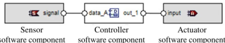
14 Chapter 2. Research Plan (a) (b) Sensor software component Controller software component Actuator software component
(a) Example of a design model
10 ms 10 ms 10 ms
(c)
Sensor SWC ControllerSWC ActuatorSWC Data sink Sensor Input Trigger sink 10 ms 10 ms(b)
Sensor SWC ControllerSWC ActuatorSWC Data sink Sensor Input Trigger sink 10 ms Sensor SWC ControllerSWC ActuatorSWC Data sink Sensor Input(a)
Trigger sink Trigger port Data port Software Circuit (SWC) 10 ms 10 ms 10 ms(c)
Sensor SWC ControllerSWC ActuatorSWC Data sink Sensor Input Trigger sink 10 ms 10 ms(b)
Sensor SWC ControllerSWC ActuatorSWC Data sink Sensor Input Trigger sink 10 ms Sensor SWC ControllerSWC ActuatorSWC Data sink Sensor Input(a)
Trigger sink Trigger port Data port Software Circuit (SWC)(b) 3 of the 8 RCM implementation models for the model in Figure 2.2a
Figure 2.2
2.3 Research Contributions 15
models for the leveraged timing analysis.
RCO 3 - Filtering mechanism. This contribution, marked as 3 in Figure 2.1, provides a conceptual mechanism supporting the selection of the best RCM implementation models for a specific, non-empty, set of timing requirements. This represents the last step in the process of leveraging timing analysis at de-sign level for driving dede-sign decisions. The proposed filtering mechanism con-sists of two cascaded filters, i.e., the elimination filter and the selection filter, as shown in Figure 2.1. After timing analysis is run on the generated RCM imple-mentation models, the RCM impleimple-mentation models and their analysis results are provided as input to the elimination filter together with the non-empty set of timing requirements specified on the vehicle functionality. The elimination fil-ter discards all the RCM implementation models whose analysis results violate the set of timing requirements. The remaining RCM implementation models, along with their analysis results, are provided as input to the selection filter. This filter further refines the selection by considering the type of component chains required from the vehicle software functionality, i.e., single-rate chain or multi-rate chain2, also received as an input. If the selection mechanism fails
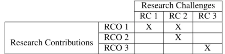
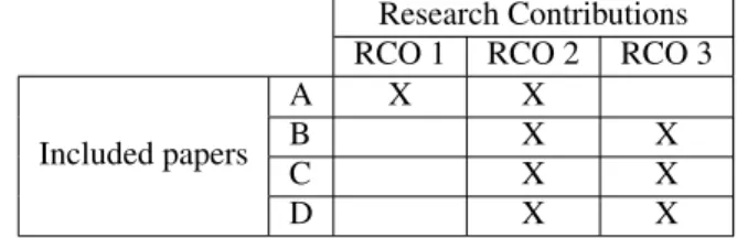
in identifying a suitable RCM implementation model, architectural refinements at the design model may be needed and the developer will be notified with a message in the console. Similarly, the developer will be notified if one (or a set of) RCM implementation model is selected. Paper B (Section 5) and Paper C (Section 6) present and discuss an initial version of the selection mechanism consisting of the elimination filter. Paper D (Section 7) describes the enhanced version of the selection mechanism consisting of the two cascade filters. Ta-ble 2.1 summarizes the relations between RCOs and RCs: RC 1 and RC 2 are addressed by the RCO 1 and RCO2, while RCO 3 addresses RC 3.
Research Challenges RC 1 RC 2 RC 3 Research Contributions RCO 1 X X RCO 2 X RCO 3 X
Table 2.1: Research Contributions in relation to the Research Challenges
2In the body electronics domain, the applications are modeled with single-rate chains whereas
14 Chapter 2. Research Plan (a) (b) Sensor software component Controller software component Actuator software component
(a) Example of a design model
10 ms 10 ms 10 ms
(c)
Sensor SWC ControllerSWC ActuatorSWC Data sink Sensor Input Trigger sink 10 ms 10 ms(b)
Sensor SWC ControllerSWC ActuatorSWC Data sink Sensor Input Trigger sink 10 ms Sensor SWC ControllerSWC ActuatorSWC Data sink Sensor Input(a)
Trigger sink Trigger port Data port Software Circuit (SWC) 10 ms 10 ms 10 ms(c)
Sensor SWC ControllerSWC ActuatorSWC Data sink Sensor Input Trigger sink 10 ms 10 ms(b)
Sensor SWC ControllerSWC ActuatorSWC Data sink Sensor Input Trigger sink 10 ms Sensor SWC ControllerSWC ActuatorSWC Data sink Sensor Input(a)
Trigger sink Trigger port Data port Software Circuit (SWC)(b) 3 of the 8 RCM implementation models for the model in Figure 2.2a
Figure 2.2
2.3 Research Contributions 15
models for the leveraged timing analysis.
RCO 3 - Filtering mechanism. This contribution, marked as 3 in Figure 2.1, provides a conceptual mechanism supporting the selection of the best RCM implementation models for a specific, non-empty, set of timing requirements. This represents the last step in the process of leveraging timing analysis at de-sign level for driving dede-sign decisions. The proposed filtering mechanism con-sists of two cascaded filters, i.e., the elimination filter and the selection filter, as shown in Figure 2.1. After timing analysis is run on the generated RCM imple-mentation models, the RCM impleimple-mentation models and their analysis results are provided as input to the elimination filter together with the non-empty set of timing requirements specified on the vehicle functionality. The elimination fil-ter discards all the RCM implementation models whose analysis results violate the set of timing requirements. The remaining RCM implementation models, along with their analysis results, are provided as input to the selection filter. This filter further refines the selection by considering the type of component chains required from the vehicle software functionality, i.e., single-rate chain or multi-rate chain2, also received as an input. If the selection mechanism fails
in identifying a suitable RCM implementation model, architectural refinements at the design model may be needed and the developer will be notified with a message in the console. Similarly, the developer will be notified if one (or a set of) RCM implementation model is selected. Paper B (Section 5) and Paper C (Section 6) present and discuss an initial version of the selection mechanism consisting of the elimination filter. Paper D (Section 7) describes the enhanced version of the selection mechanism consisting of the two cascade filters. Ta-ble 2.1 summarizes the relations between RCOs and RCs: RC 1 and RC 2 are addressed by the RCO 1 and RCO2, while RCO 3 addresses RC 3.
Research Challenges RC 1 RC 2 RC 3 Research Contributions RCO 1 X X RCO 2 X RCO 3 X
Table 2.1: Research Contributions in relation to the Research Challenges
2In the body electronics domain, the applications are modeled with single-rate chains whereas