X-ray Absorption and Fragmentation
as Initial Steps of Radiation Damage
in Free Organic Molecules and
Nanoparticles
ABDUL RAHMAN ABID
Nano and Molecular Systems Research Unit (NANOMO) Faculty of Science, University of Oulu
FINLAND
Molecular and Condensed Matter Physics
Department of Physics and Astronomy, Uppsala University SWEDEN
Academic Dissertation to be presented with the assent of the Faculty of Science, University of Oulu, Finland and Department of Physics and Astron-omy, Uppsala University, Sweden for public discussion in the Auditorium L2, on April 7th, 2021, at 11 o’clock (EEST) morning.
REPORT SERIES IN PHYSICAL SCIENCES Report No. 139 OULU • UPPSALA (2021)
Prof. Olle Bj¨orneholm, Uppsala University, Sweden Adj. Prof. Juha Nikkinen, University of Oulu, Finland Opponent:
Dr. Laurent Nahon, Synchrotron SOLEIL, Saint-Aubin, France Reviewers:
Dr. Joachim Schulz, EuXFEL, Hamburg, Germany Dr. Paola Bolognesi, CNR-ISM, Rome, Italy Custos:
Prof. Marko Huttula, University of Oulu, Finland
Cover Design by Abdul Rahman Abid ISBN 978-952-62-2884-6 (Printed) ISBN 978-952-62-2885-3 (PDF) ISSN 1239-4327
PunaMusta Oy
“No two things have been combined together better than knowledge and patience.” -Muhammad (PBUH)
Abid, Abdul Rahman: X-ray Absorption and Fragmentation as Initial Steps of Radiation Damage in Free Organic Molecules and Nanoparticles
Nano and Molecular Systems Research Unit, Faculty of Science P.O. Box 3000
FIN-90014 University of Oulu FINLAND
Molecular and Condensed Matter Physics Department of Physics and Astronomy Box 516, Uppsala University
SE-751 20 Uppsala SWEDEN
Abstract
Understanding the molecular radiation damage is crucial in radiobiology, molecular physics, and atmospheric science. In this thesis, the initial steps of radiation damage of anhydrous gas-phase molecules and hydrated nanoparti-cles were studied using synchrotron radiation based electron-ion coincidence spectroscopy and X-ray absorption spectroscopy under vacuum conditions. Electron - ion coincidence spectroscopy was used to study the photofrag-mentation and molecular dynamics of the isolated gas-phase molecules. In addition to the photofragmentation of the gas-phase molecules, the effect of the initial ionization site, initial molecular geometry, and the intramolecu-lar chemical environment has been studied. In avobenzone, core ionization leads to massive fragmentation, with a slight site-selectivity concerning frag-ment production. In ortho-aminobenzoic acid, core ionization leads to the production of a hydronium ion, indicating that the importance of functional group’s position for double intramolecular hydrogen transfer. X-ray absorp-tion spectroscopy was used to probe hydrated nanoparticles prepared at dif-ferent relative humidities. In hydrated inorganic and mixed inorganic-organic nanoparticles, water is present in a liquid-like state. With different ranges of relative humidity, the primary hydration layers of the hydrated nanoparti-cles stays the same. In mixed nanopartinanoparti-cles, there is evidence for interaction between the included organic biomolecule with the inorganic and/or water molecules.
Key words: Coincidence spectroscopy, PEPI(PI)CO, electron spectroscopy, X-ray absorption spectroscopy, mass spectrometry, photodissociation, gas-phase, liquids, nanoparticles, charge transfer, synchrotron radiation
ss¨a ja nanopartikkeleissa
Nano and Molecular Systems Research Unit, Faculty of Science P.O. Box 3000
FIN-90014 University of Oulu FINLAND
Molecular and Condensed Matter Physics Department of Physics and Astronomy Box 516, Uppsala University
SE-751 20 Uppsala SWEDEN
Abstrakti
Molekyylitasolla tapahtuvien s¨ateilyvaurioiden ymm¨arrys on eritt¨ain t¨arke¨a¨a s¨ateilybiologiassa, molekyylifysiikassa ja ilmakeh¨atieteiss¨a. T¨ass¨a ty¨oss¨a on tutkittu tyhji¨oolosuhteissa s¨ateilyvaurioiden alkuaskeleita vedett¨omiss¨a kaa-sumaisissa molekyyleiss¨a ja vett¨a sis¨alt¨aviss¨a nanohiukkasissa k¨aytt¨aen synkr-otronis¨ateilypohjaista elektroni-ionikoinsidenssispektroskopiaa ja r¨ ontgenab-sorptiospektroskopiaa. Elektroni-ionikoinsidenssispektroskopialla tutkittiin s¨ateilyn aikaansaamaa hajoamista ja molekyylidynamiikkaa eristetyiss¨a kaa-sumolekyyleiss¨a. T¨am¨an lis¨aksi tutkittiin, kuinka ensimm¨aisen ionisaatiota-pahtuman paikka, molekyylin geometria ja molekyylin sis¨ainen kemiallinen ymp¨arist¨o vaikuttaa n¨aihin prosesseihin. Avobentsonimolekyylin sis¨akuoren ionisaatio johtaa molekyylin hajoamiseen lukuisiksi eri hajoamistuotteiksi, ja hajoamistuotteiden saannin todettiin riippuvan vain v¨ah¨an ionisoidusta sis¨akuoresta. Orto-aminobentsoehapossa sis¨akuoren ionisaation havaittiin tuottavan kahden vedyn siirtymisen vaativaa hydroniumionia, ja tuoton havait-tiin riippuvan funktionaalisten ryhmien keskin¨aisest¨a paikasta. R¨ ontgenab-sorptiospektroskopiaa hy¨odynnettiin eri suhteellisissa ilmankosteuksissa valmis-tettujen nanohiukkasten tutkimuksessa. N¨aiss¨a ep¨aorgaanisissa ja saoste-tuissa orgaanisissa-ep¨aorgaanisissa nanohiukkasissa veden havaittiin olevan nesteenkaltaisessa olomuodossa. Saostetuissa nanohiukkasissa n¨ahtiin my¨os merkkej¨a orgaanisen biomolekyylin ja ep¨aorgaanisen ja/tai veden v¨alisest¨a vuo-rovaikutuksesta.
Avainsanat: Koinsidenssispektroskopia, PEPIPICO, elektronispektroskopia, r¨ontgenabsorptiospektroskopia, massaspektroskopia, fotodissosiaatio, kaasu-faasi, neste, nanohiukkaset, varauksen siirto, synkrotronis¨ateily
Abid, Abdul Rahman: R¨ontgenabsorption och fragmentering som initiala steg f¨or str˚alskador i fria organiska molekyler och nanopar-tiklar
Nano and Molecular Systems Research Unit Naturvetenskapliga fakulteten
Box 3000, FIN-90014 University of Oulu FINLAND
Kemisk och biomolekyl¨ar fysik Institutionen f¨or fysik och astronomi Box 516, Uppsala universitet
SE-751 20 Uppsala SVERIGE
Sammanfattning
F¨orst˚aelse av molekyl¨ara str˚alningsskador ¨ar avg¨orande inom radiobiologi, molekyl¨ar fysik och atmosf¨arsvetenskap. I denna avhandling studerades str˚alningsskadornas inledande steg hos gasfasmolekyler och hydratiserade nanopartiklar med hj¨alp av synkrotronstr˚alningsbaserad elektron-jon- koinci-densspektroskopi och r¨ontgenabsorptionsspektroskopi under vakuumf¨orh˚ alla-nden. Elektron-jon-koincidensspektroskopi anv¨andes f¨or att studera fotofrag-mentering och molekyl¨ar dynamik hos de isolerade gasfasmolekylerna. F¨ oru-tom fotofragmenteringen av gasfasmolekylerna har effekten av den initiala joniseringsplatsen i molekylen, den initiala molekyl¨ara geometrin och den in-tramolekyl¨ara kemiska milj¨on studerats. I avobenzon leder innerskalsjoniser-ing till massiv fragmenterinnerskalsjoniser-ing med liten platsselektivitet betr¨affande fragment-produktion. I orto-aminobensoesyra leder innerskalsjonisering till produktion av en hydroniumjon, vilket pekar p˚a vikten av funktionella gruppers position f¨or s˚adan dubbel intramolekyl¨ar v¨ate¨overf¨oring. R¨ ontgenabsorptionsspek-troskopi anv¨andes f¨or att studera hydratiserade nanopartiklar framst¨allda vid varierande relativa fuktighet. I hydratiserade inorganiska och blandade inorganiska-organiska nanopartiklar finns vatten i v¨atskeformigt tillst˚and. De prim¨ara hydratiseringsskalen i de hydratiserade nanopartiklarna op˚averkade av de olika relativa fuktighetsniv˚aerna. I blandade nanopartiklar finns det bevis f¨or v¨axelverkan mellan de inkluderade organiska biomolekylerna och de inorganiska jonerna och/eller vattenmolekylerna.
Nyckelord: koincidensspektroskopi, PEPI(PI)CO, elektronspektroskopi, r¨ ont-genabsorptionsspektroskopi, masspektrometri, fotodissociation, gasfas, v¨ atsk-or, nanopartiklar, laddnings¨overf¨oring, synkrotronstr˚alning
Acknowledgments
The present work was carried out in the Nano and Molecular (NANOMO) Re-search Unit of the University of Oulu, Finland, and Molecular and Condensed Matter Physics of the Uppsala University, Sweden. This project has received funding from the European Union’s Horizon 2020 research and innovation programme “I4Future” under the Marie Sklodowska-Curie grant agreement (No. 713606). This project also received funding from V¨ais¨al¨a Fund, Finnish Academy of Science and Letters to finalize my doctoral thesis. This project was also granted travel funding from CALIPSOPlus from the EU framework programme for research and innovation Horizon 2020 (Grant agreement no. 730872), the Magnus Ehrnrooth Foundation, Finland, and the University of Oulu Graduate School (UniOGS) for several beamtimes and research visits. I want to thank my supervisors, Assoc. Prof. Minna Patanen, Prof. Olle Bj¨orneholm, and Adj. Prof. Juha Nikkinen guided me through the challeng-ing time of the doctoral research and have all the patience and understandchalleng-ing required while working with me. Especially, Minna and Olle, I know that such a dedication to supervision and support is rare. I learned many things from the discussions we have during our meetings. A special thanks to the NANOMO research unit head, Prof. Marko Huttula, for his support, who facilitated me throughout my doctoral research. I am also grateful to Profs. Ville-Veikko Telkki and Mika Nieminen as members of my doctoral follow-up group and guidance during the follow-up meetings.This work is a result of intensive teamwork, so I would like to thank my colleagues Nacer Boudjemia, Eetu Pelimanni, Maximilian Reinhardt, Geor-gia Michailoudi, Paavo Turunen, and Tuomas L¨oytynoja for their valuable discussions and assistance. We did many discussions not only related to the work but anyway interesting and piquant at the intellectual level. I also appreciate the mental support which I got from the other members of the NANOMO research unit. I want to thanks Drs. Conny S˚athe, Takashi Tokushima, Victor Ekholm, and Nial Wassdahl for the facilitation and sup-port during research visits at VERITAS Beamline, MAX IV Laboratory. As the work was based on experimental activities, none of it would have been possible without the support of beamline staff Drs. Antti Kivim¨aki, Kirill Chernenko, Gunnar ¨Ohrwall, and Aleksandar Milosavljevi´c from MAX IV and SOLEIL. I am thankful to Drs. Joachim Schulz and Paola Bolognesi
Even though doctoral studies have been challenging, it is only a small frac-tion of the bigger life journey during which I have continuously received support and appreciation from my family. Thanks to my parents, Asghar Ali and Khursheed Begum, for giving me their full support, understanding, and prayers to freely follow my aspirations. I also want to thank my broth-ers and sistbroth-ers, Nadeem, Naeem, Kalsoom, Kausar, and Ansa, for supporting me in several phases of my life. Last but not least, I want to thank my beloved wife, Dr. Somia, for always creating the best environments for me so I can follow my dreams and our daughter Samavia for providing the critical work-life balance and so much bliss to our life in Finland.
LIST OF ORIGINAL PAPERS
The present thesis contains an introductory part and the following papers which will be referred in the text by their Roman numbers.
I. A. R. Abid, E. Pelimanni, M. Reinhardt, N. Boudjemia, A. Kivim¨aki, M. Huttula, O. Bj¨orneholm, and M. Patanen: Electron-ion coinci-dence spectroscopy of a large organic molecule: Photofragmentation of avobenzone after valence and core ionisation J. Phys. B: At. Mol. Opt. Phys. 53, (2020) 244001. (DOI: 10.1088/1361-6455/abc228)
II. A. R. Abid, O. Vetel¨ainen, N. Boudjemia, E. Pelimanni, A. Kivim¨aki, M. Alatalo, M. Huttula, O. Bj¨orneholm, and M. Patanen: Isomer-Dependent Formation of H3O+ via Intramolecular Double Hydrogen
Transfer in Aminobenzoic Acid (2021). (Manuscript)
III. A. R. Abid, M. Reinhardt, N. Boudjemia, E. Pelimanni, A. R. Milosavl-jevi´c, C.-M. Saak, M. Huttula, O. Bj¨orneholm, and M. Patanen: The effect of relative humidity on CaCl2 nanoparticles studied by soft
X-ray absorption spectroscopy RSC Adv., 11, (2021) 2103–2111. (DOI:
10.1039/D0RA08943E)
Comment on my own contribution:
All the papers for this doctoral dissertation are a result of teamwork. My doctoral research is the outcome of the continuous collaboration between the Oulu and Uppsala universities. Besides that, active collaboration with differ-ent large scale facilities, this experimdiffer-ental work would not have been possible. To clarify my contributions to the publications. For all Papers I-III, I have been the main responsible person. The main responsibilities include planning and conducting experimental measurements, data collection, data treatment, and reporting the results.
List of Abbreviations
hν Photon Energy
AES Auger Electron Spectroscopy ALS Aerodynamics Lens
BO Born-Oppenheimer CaCl2 Calcium Chloride
cPGM Collimated Plane Grating Monochromator EPU Elliptically Polarizing Undulator
HDA Hemispherical Deflection Analyzer HOMO Highest Occupied Molecular Orbital KE Kinetic Energy
KER Kinietic Energy Release
LCAO Linear Combinations of Atomic Orbitals Linac Linear Accelerator
MCP Micro Channel Plate MO Molecular Orbital
NEXAFS Near-Edge X-ray Absorption Fine Structure
PEPI(PI)CO Photoelectron, Photoion (Photoion) Coincidence Spectroscopy PES Photoelectron Spectroscopy
Phe Phenylalanine
RAD Resistive Anode Detector RAS Resonant Auger Spectroscopy RIXS Resonant Inelastic X-ray Scattering SPF Short-Pulse-Facility
TEY Total Electron Yield TOF Time-Of-Flight
TOF-MS Time-Of-Flight Mass Spectroscopy UFD Ultrafast Dissociations
UPS Ultraviolet Photoelectron Spectroscopy UV Ultraviolet
XAS X-ray Absorption Spectroscopy XES X-ray Emission Spectroscopy XPS X-ray Photoelectron Spectroscopy XUV Extreme Ultraviolet
Contents
Abstract i
Abstrakti ii
Sammanfattning iii
Acknowledgments iv
List of original papers vii
List of Abbreviations and Symbols viii
Contents xi
1 Introduction 1
2 Physical Foundation 5
2.1 Electronic Structure of Molecules . . . 5
2.2 Potential Energy Curves . . . 7
2.3 Light-Matter Interaction . . . 9
2.3.1 Photoionization or Photoelectric Effect . . . 9
2.3.2 Photoexcitation or Resonant Excitation. . . 11
2.3.3 Fluorescence Decay . . . 13
2.3.4 Spectroscopy Techniques . . . 13
2.4 Molecular Dissociation and Fragmentation . . . 14
3 Synchrotron Radiation and Sample Delivery Systems 19 3.1 Synchrotron Radiation . . . 19
3.2 Characteristics of Synchrotron Radiation . . . 21
3.2.1 Undulator Radiation . . . 21
3.3 FinEstBeAMS Beamline at MAX IV . . . 23
3.4 Sample Delivery Systems . . . 25
3.4.1 Vapor Production . . . 25
3.4.2 Free-Standing Nanoparticles Preparation . . . 26
4 Spectroscopic Methods and Data Handling 31
4.1 Electron Spectroscopy . . . 31
4.2 Time-of-Flight Mass Spectroscopy . . . 34
4.3 X-ray Absorption Spectroscopy . . . 37
4.4 Electron-Ion Coincidence Spectroscopy . . . 38
4.4.1 PEPI(PI)CO Technique and Apparatus . . . 39
4.4.2 CoboldPC Program Package . . . 41
5 PEPIPICO Data Analysis 43 5.1 Basic PEPIPICO Data Handling . . . 43
5.2 Dissociation Mechanisms . . . 43
5.2.1 Two-Body Dissociation . . . 44
5.2.2 Many-Body Dissociation . . . 45
5.3 Pattern Slope Calculation . . . 46
5.4 Challenges in Coincidence Spectroscopy Technique . . . 50
6 Research Objectives and Results 53 6.1 Photofragmention of Molecules - Papers I & II . . . 53
6.1.1 Photofragmentation of Avobenzone - Paper I . . . 53
6.1.2 Photofragmentation of Ortho-Aminobenzoic Acid - Pa-per II . . . 58
6.2 XAS of Hydrated Nanoparticles - Paper III . . . 59
7 Conclusion and Outlook 63
Popul¨arvetenskaplig sammanfattning 65
CHAPTER
1
Introduction
Radiation Damage: What and Where?
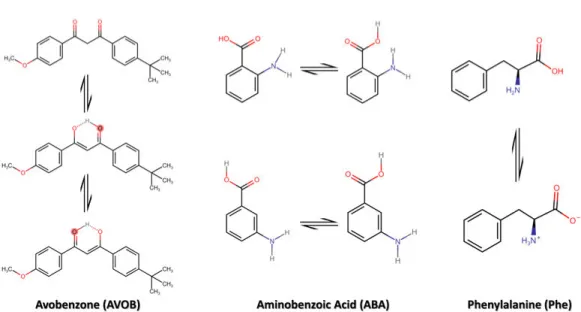
The importance of radiation-sensitive molecules in radiobiology and medicine is the primary motivation for these studies. For many decades, radiation damage caused by ionizing radiation (i.e. UV and X-rays) on biologically rel-evant molecules has been widely studied. These molecules also have several other applications like plastics, paints, and electronic devices, and moreover, they also have atmospheric relevance. Therefore, a microscopic understand-ing of these molecules, their electronic structure, and ionization processes is needed. Biomolecules often have several structural and conformational iso-mers, and one of the exciting perspectives in molecular physics is to study how properties vary between isomers. They also can have different molecular structures in gas-phase, in solutions, and as solids. The variety of interesting aspects in these biologically relevant molecules motivated us to study changes in the photofragmentation and photoabsorption processes connected to small structural variations in the molecules.
In this thesis, we studied organic and inorganic biologically relevant molecules. In Papers I & II, we performed gas-phase studies of avobenzone and aminoben-zoic acid (organic) in different isomeric forms, as shown in figure 1.1. In Paper III, we generated hydrated nanoparticles of calcium chloride (CaCl2)
salt (inorganic) to study hydration properties. We also generated mixed inorganic-organic hydrated nanoparticles from CaCl2and phenylalanine1(Phe).
Seeing Through Soft X-ray Spectroscopic Methods
Molecular radiation damage can be studied using different spectroscopic methods like mass spectrometry[1], electron spectroscopy[1], X-ray absorp-tion spectroscopy[2], and X-ray emission spectroscopy[3]. Upon
Figure 1.1: Chemical structure of organic molecules studied in this thesis with their isomers and conformers.
tion, one or more bond cleavages happen and lead to the fragmentation of the molecule. The created positive fragments are detected with the help of mass spectrometry. These fragments will give information about the possible sites of the bond break. Photoelectrons (and/or Auger electrons) are also ejected with different kinetic energy during photoionization. These electrons contain information about the electronic structure.
The amalgamation of electron spectroscopy and mass spectrometry allows electron detection to act as a timestamp for the starting point of ion detec-tion. This technique is known as electron-ion coincidence spectroscopy. In this way, we can get the complete picture of the ionization processes in the system by recording several ionization events.
X-ray absorption spectroscopy (XAS) is a well established technique that provides element-specific information. Element-specific changes in XAS fea-tures give information on, in addition to the local atomic structure, lattice parameters, molecular orientation, density of states, the nature, orientation, and length of chemical bonds[4, 5]. This technique is capable to probe the solute’s solvation environment like salts and biomolecules in water[6].
What We Did?
In this thesis, various spectroscopic methods were applied to study radia-tion damage in different radiaradia-tion-sensitive biologically relevant molecules. All the experimental measurements were done using synchrotron radiation.
In Papers I & II, the studies consist of the photofragmentation of iso-lated gas-phase molecules with electron-ion coincidence spectroscopy. These studies help us to understand the fragmentation mechanisms and dynamics of the molecules. In Paper III, hydrated nanoparticles were studied with X-ray absorption spectroscopy. Different absorption edges were probed to learn about changes in the ions’ and molecules’ local structure and chemi-cal environment. The presence and state of water within the nanoparticles were also investigated. From a broad perspective, these studies are benefi-cial for understanding radiation damage in molecules in anhydrous (isolated gas-phase) and hydrated (nanoparticles) form using synchrotron radiation. Moreover, the properties of nanoaerosols studied in Paper III are relevant for atmospheric science.
Structure of The Thesis
The introductory part of the thesis is structured as follows. Chapter 2: Phys-ical Foundation explains the fundamental physPhys-ical concepts lying behind our research work. Chapter 3: Synchrotron Radiation and Sample Delivery Sys-tems describes the importance of synchrotron radiation and beamlines used for the measurments presented in Papers I-III. The sample delivery sys-tems used in Papers I-III are also described in this chapter. Chapter 4: Spectroscopic Methods and Data Handling explains the spectroscopic meth-ods used in Papers I-III and the post-experimental data handling. Chapter 5: PEPIPICO Data Analysis describes how sequential fragmentation can be analyzed through PEPIPICO spectroscopy and how the data analysis was done in Papers I & II. Chapter 6: Research Objectives and Results explains the main objectives behind our research and summarizes the results obtained. The last Chapter 7: Conclusion and Outlook concludes the introduction of the thesis and discusses some possible future research paths.
CHAPTER
2
Physical Foundation
2.1
Electronic Structure of Molecules
Atoms consist of a densely packed positively charged nucleus having posi-tively charged protons and neutral neutrons, around which negative electrons revolve, pictured as a hollow spherical assembly. In the atoms, the electrons are distributed in different orbitals. These electron orbitals are described by an electron wavefunction (ψ) written in terms of their spin and angular momenta. The wavefunctions can be obtained by solving the Schr¨odinger equation, which also yields the different energy states of an atom.
ˆ
Hψ = Eψ (2.1)
In the equation 2.1, H is a Hamiltonian, which operates on the wavefunc-ˆ tion and gives eigenenergies (E) of the system [7–9]. The solution of the Schr¨odinger equation gives the set of quantum numbers related to atomic orbitals. These quantum numbers are the principal quantum number (n) having always a value n ≥ 1, the azimuthal (angular) quantum number (l) having always a value 0 ≤ l ≤ n–1, the magnetic quantum number (ml)
hav-ing always a value −l ≤ ml≤ +l, and the spin quantum number (ms) having
always a value ms = ±1/2 [10]. The combination of these quantum numbers
with different coupling schemes gives rise to different electron configurations and provides a description of the different quantum states.
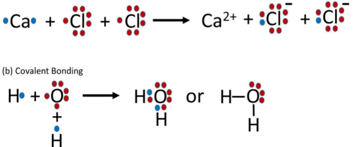
In molecules, two or more atoms are interlinked with each other by ‘do-nating’ or ‘sharing’ electrons [11]. Donating or sharing electrons results in ionic or covalent bonds, respectively. The outermost valence electrons con-tribute to the bond formation process simplistically described in the Lewis structure model, as shown in figure 2.1 [12–17]. In the Lewis model, the electrons are allocated to a specific atom in the molecule, but in reality, that is not the case. The bonding theory is better described in molecular orbital (MO) theory, in which electrons are more delocalized. There are numbers of
molecular orbital theory descriptions available in the literature [11, 18–21]; here, a small introduction is given.
Figure 2.1: In the Lewis Model, (a) ionic bonding of a molecule consists of donating electrons and (b) covalent bonding of a molecule consists of sharing electrons.
Molecular orbitals can be described in terms of linear superpositions of atomic orbitals of every individual atom (linear combination of atomic or-bitals (LCAO) approximation [21–24]).
ψ =X
i
ai.φi (2.2)
In equation2.2, ψ is a molecular orbital, ai is a mixing coefficient describing
the relative contribution of each atomic orbital, and φi is an atomic orbital.
It is very useful to describe molecular orbitals by breaking them into atomic orbitals, since this will give us the information about the bonding properties of the molecule [25].
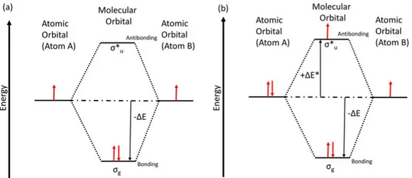
The schematics of a diatomic molecule are shown in figure 2.2, to explain how MOs are formed. When atomic orbitals on the different atoms over-lap, two different distinct molecular orbitals are produced; one is a bonding combination indicated as σg. In the bonding state, molecular orbitals have
maximum electron density between the nuclei, resembling the electron pair in the Lewis model. The other state called an anti-bonding states, indicated as σu∗, has a node in electron density between the nuclei. Therefore, we can say that the outdated Lewis model is replaced by the molecular orbital the-ory, which can describe how atoms bond into molecules (bonding state) or dissociate (anti-bonding state). The sign of the atomic orbitals is vital to
2.2 Potential Energy Curves
define the MOs’ nature: with the same sign bonding MO form, but with opposite sign, anti-bonding MO will form. No interaction of atomic orbitals results in non-bonding MOs.
Figure 2.2: Schematic of the molecular orbitals of a molecule with both atoms having (a) the same number of electrons in valence orbitals (b) different number of electrons in valence orbitals.
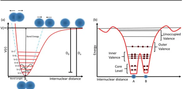
The atomic orbitals are often categorized into valence and core orbitals. The valence orbitals are delocalized and contribute to the chemical bonding of the molecule. The core orbitals are localized and have higher binding en-ergies, as shown in figure 2.3(b). The valence orbitals interact with other valence orbitals more strongly than the core orbitals, so core orbitals of MOs are much more similar to their atomic counterparts compared to the valence orbitals. In the thesis, we probed both valence and core-levels of molecules.
2.2
Potential Energy Curves
Molecules always have some most suitable geometry with a minimum energy. There is an equilibrium distance between the atoms in this preferred geome-try, and energy is required to move apart atoms from each other or closer to each other. Figure 2.3 shows a schematic potential energy curve i.e. energy as a function of intermolecular distance.
To visualize potential energy curves, different approximations have been de-veloped:
(i) Parabolic Approximation: This approximation is valid close to the equi-librium distance Re.
Figure 2.3: (a) A schematic potential energy curve of a diatomic molecule showing a Morse potential (red line) and a parabolic approximation (blue line). (b) A schematic of the diatomic molecule with orbitals energy levels.
(ii) Morse Potential: For larger intermolecular distance, a more accurate approximation is needed to model the potential energy curve. Morse poten-tial is mostly used to describe the potenpoten-tial energy for diatomic molecules, and it takes into account the bond breaking of the molecule. The Morse potential has the following potential energy function:
V (r) = De.(1 − e−a(r−Re))2 (2.3)
In the equation2.3, V (r) is the potential energy, De is the depth of the well,
Re is the equilibrium distance, r is the intermolecular distance, and a is the
width of the potential well (the smaller the number the larger is the width) [26, 27].
The dissociation energy (D0) is a little different from the depth of the
poten-tial well (De). D0 is defined as the minimum energy required to convert the
bound state (lowest possible state) of the molecule to a state with an infinite internuclear distance. For a diatomic molecule, the dissociation energy D0 is
of the order of few eV. For covalently bound molecules (e.g., hydrocarbons studied in this thesis), the internuclear equilibrium distances between bound atoms are the order of 1-3 ˚A [26].
The Morse potential is accurate and useful for a diatomic molecule. For polyatomic molecules, the potential is replaced by a multidimensional po-tential energy surface. More rotational and vibrational modes exist, and the potential is generally more complex.
2.3 Light-Matter Interaction
2.3
Light-Matter Interaction
Electromagnetic radiation can be described as small discrete energy packets called photons because of the wave-particle duality. Every photon has a dis-crete energy E = hν, where h is Planck’s constant and ν the frequency of the light. When photons with energy more than some specific energy interact with electrons occupying the atomic or molecular orbitals, different electronic transitions occur. In these electronic transitions, one quantum state changes to another state, following a defined set of rules. These electronic transi-tions provide information about the structure of a molecule or an atom and molecule’s dissociation mechanism. Some of these electronic transitions are described below.
2.3.1
Photoionization or Photoelectric Effect
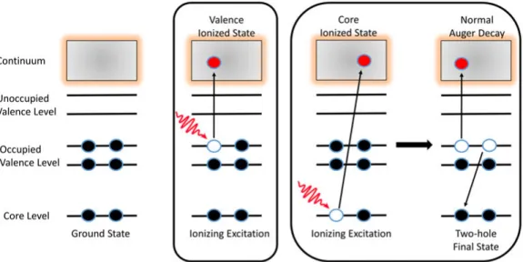
One of the most important and commonly occurring electronic transitions due to photon-electron interaction is called the photoelectric effect or pho-toionization. The photoelectric effect was discovered by Heinrich Hertz in 1887 [28], and explained by Einstein in 1905 [29]. In this process, a photon with energy hν greater than the electron’s binding energy interacts with a specific atomic orbital, causing the electron from that orbital to be ejected into the continuum, and photoionization will occur. The schematic diagram is shown in figure 2.4 and the process can be written as:
M + hν → M++ e−
The electron kicked out from the atom is called a photoelectron. The en-ergy of the photoelectron depends on the enen-ergy of the photons hν. The photoelectron energy, according to Einstein equation, is the following:
KE = hν − BE (2.4)
In the equation 2.4, KE is the kinetic energy of the photoelectron, BE is the binding energy required to remove an electron from a specific orbital of the atom/molecule. In molecules, photoionization can be accompanied by vibrational and rotational excitations [30–32]. Koopman’s theorem is a first approximation to the binding energy calculation [33]. According to the the-orem, the first ionization energy of the molecule (or atom) is equal to the negative value of the orbital energy. Photoionization can lead to dissociation of the molecule, which is described in section 2.4. The probability for pho-toionization depends on the phopho-toionization cross-section. The cross-section varies from orbital to orbital and element to element as a function of pho-ton energy. The ionization cross-section is most commonly maximum close to the threshold ionization energies and decreases with increasing photon
energy. Different photon energies are required to probe different orbitals. Using ultraviolet (UV) light we can probe outer valence orbitals. Soft X-ray allows probing inner valence and some core-levels, and with hard X-rays the innermost core-levels of high atomic number elements can be reached.
Figure 2.4: Schematic of photoionization of valence- and level and core-level relaxation process leading to a normal Auger decay.
Normal Auger Decay
As a core-level of an atom is photoionized, a hole is created in the core orbital. This leaves the atom in a highly excited and unstable form leading to deexcitation via radiative (explained afterwards) or non-radiative processes. When dealing with light elements (Z<30), the non-radiative Auger process is more dominant [24]. In a normal Auger decay, the core hole is filled by an electron from one of the higher orbitals (valence orbitals), and at the same time, another electron, called the Auger electron, is emitted, as shown in the figure2.4. After the Auger decay, the atom is in a doubly ionized state because of the ejection of two electrons (photo and Auger electron) [34]. The normal Auger decay does not follow electric dipole selection rules [25].
M −→ M∗++ ep −→ M+++ eA
The Auger electron’s kinetic energy is defined as the energy difference be-tween the core ionized state (intermediate state) and the doubly charged state (final state).
2.3 Light-Matter Interaction
2.3.2
Photoexcitation or Resonant Excitation
Atoms have occupied and unoccupied orbitals; if the photon energy hν is lower than the binding energy, electron from a specific orbital can move from an occupied orbital to an unoccupied orbital. This process is known as a photoexcitation or a resonant excitation and can be written as:
M + hν −→ M∗+
The photoexcitation or resonant excitation is only possible if photon energy matches the following condition:
hν = Eexcited−state− Eground−state (2.5)
In the equation 2.5, Eground−state and Eexcited−state are the energies of the
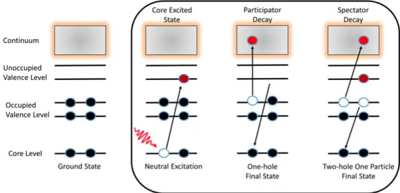
ground state and the excited state, respectively[30, 35]. This excited state is unstable and eventually decays into some stable state by fragmentation and/or resonant electron decay. The schematic of the process is shown in figure 2.5.
Figure 2.5: Schematic of colevel photoexcitation of the electron and re-laxation process showing resonant Auger decay (participator or spectator decay).
Photoexcitation follows the set of rules based on the electric dipole approx-imation. The approximation is applicable for UV and soft X-ray regions; for higher interaction energies, higher multipoles of electromagnetic radia-tion also contribute. The result of the electric dipole approximaradia-tion is the electric dipole selection rules. The transition moment integral is the basis of
spectroscopic selection rules: − → M = Z ψf∗µψidτ (2.6)
In equation2.6,−M is the transition moment, ψ→ i is the wavefunction of initial
state, ψf∗ is a conjugate of the wavefunction of final state, µ is the dipole mo-ment operator, and dτ is the infinitesimal elemo-ment. For example in molecules, the total spin cannot change, ∆S = 0; for multiplets, the rule ∆Σ = 0 hold and the total angular momentum change should be ∆Λ = 0, ±1 (Λi = 0 to
Λf = 0 is forbidden) [36, 37]. The initial and final state have to be of
op-posite parity. The transition in any quantum mechanical system is governed by these selection rules [26,38].
Resonant Auger Decay
As one of the atom’s core-levels is photoexcited, the atom or molecule will go into an unstable excited state that leads to the deexcitation of the atom and molecule into some more stable state. The core hole is then filled like in the normal Auger decay and singly charged states are produced. This process is called a resonant Auger decay, and the electron ejected is called a resonant Auger electron. The ejected electron energy will be equal to the excess energy of the transition[39]. The schematic is shown in figure2.5 and process is described as:
M + hν −→ M∗ −→ M++ e A
The resonant Auger decay is further classified into two different categories, based on whether the initially excited electron participates in the relaxation process or not[40, 41].
(i) Participator Resonant Decay: In this decay, the excited electron partic-ipates in the relaxation process and can go back into the original core-level or be ejected as the resonant Auger electron, as shown in figure 2.5. The participator resonant decay results in valence single-hole states like direct valence ionization.
(ii) Spectator Resonant Decay: In this decay, the core-excited electron will act as the observer and does not participate in the relaxation process. The resonant Auger electron will be from another orbital instead of the excited core electron. The spectator resonant decay results in a valence two-hole/one-particle states. Spectator decay final states can also be accessed through the combined ionization and shake-up process.
2.3 Light-Matter Interaction
ion, electron, or photon bombardment. For probing resonant auger decay, tunable synchrotron is a convenient source, but this can also be achieved by other sources like energetic particle collisions.
2.3.3
Fluorescence Decay
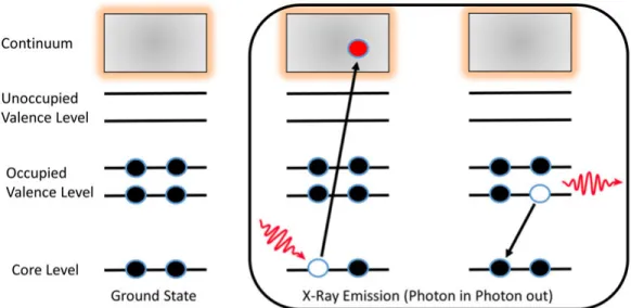
As we described earlier, in photoionization and photoexcitation processes when a photon interacts with the matter, an electron may be ejected after the relaxation. However, there is also a decay where a photon is emitted after or during the relaxation. This process is known as a fluorescence decay [42, 43]. The schematic is shown in figure 2.6 and processes are described below.
(i)Fluorescence Decay by Photoionization: M + hν −→ M++ hν0+ e−
(ii)Fluorescence Decay by Photoexcitation: M + hν −→ M∗+ hν0
2.3.4
Spectroscopy Techniques
There are experimental techniques used to study atoms and molecules based on the above electronic transitions. Ultraviolet photoelectron spectroscopy (UPS) is used to study the atoms’ and molecules’ valence electronic struc-ture. In UPS, ultraviolet light is used to irradiate the sample, and then the kinetic energy of the emitted electrons is measured with the help of an electron spectrometer. Likewise, X-ray photoelectron spectroscopy (XPS) is used to study core-level electrons, and the sample is irradiated with X-rays instead of UV.
Moreover, non-radiative decay processes are studied with Auger Electron Spectroscopy (AES) or Resonant Auger Spectroscopy (RAS). AES and RAS can help us to study the relaxation processes and to get information about the orbitals taking part in the decay of an excited atom or a molecule. If the atoms or molecules decay by ejecting photons, to study this decay process, if it is non-resonant, then X-ray Emission Spectroscopy (XES) is used, and if it is resonant, then Resonant Inelastic X-ray Scattering (RIXS) is used. All the above experimental techniques help us to understand the atom’s or molecule’s electronic structure as a whole.
In this thesis, we apply some of these techniques for a molecular-level under-standing of our systems. In Paper I and Paper II, we collected outer valence electrons using UPS and core electrons using XPS techniques, and photo-electrons acted as start pulse for ion extraction for a time-of-flight (TOF)
spectrometer used in electron-ion coincidence technique. In Paper III, we collected core and Auger electrons in total and partial electron yield modes in order to obtain X-ray absorption spectra (XAS).
Figure 2.6: A Schematic of the core-level photoionization and relaxation process with the emission of a photon.
2.4
Molecular Dissociation and Fragmentation
When a molecule absorbs energy and increases its internal energy, the molecule rearranges itself or dissociates and fragments into smaller parts to reduce its energy. The electrons can be ejected at any stage (before, during, and after) of the dissociation process. These electrons give qualitative and quan-titative information about the dissociation processes [44]. The ions created by these dissociation processes are also studied using different ion detection techniques. In this thesis, positive ions are studied with a TOF spectrometer. In the well-known Born-Oppenheimer (BO) approximation, the electron’s movement is considered to be much faster than the nuclear motion due to the difference in the mass of the nucleus and electron. We can thus sepa-rate the electronic and nuclear wavefunctions of the molecule, and the BO approximation is based on two underlying assumptions [45]:
(1) Nuclear motion occurs in a smeared out potential from the fast elec-trons.
(2) The electronic wavefunction depends upon nuclear positions but not ve-locities.
2.4 Molecular Dissociation and Fragmentation
Equations 2.7a & 2.7b are two different ways for mathematical represen-tation of the BO approximation.
ψmolecule = ψelectron.ψnuclei (2.7a)
Etotal = Eelectronic+ Evibrational+ Erotational+ Enuclear−spin (2.7b)
Equation2.7a describes the wavefunction of the molecule as product of elec-tronic (ψelectron) and nuclear (ψnuclei) wavefunctions. In equation 2.7b, the
molecular energy is the sum of all independent terms with different order of magnitude.
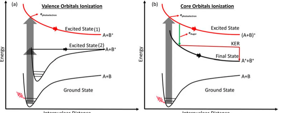
An electronic transition happens fast from one state to another without any change in the molecule’s nuclear geometry and thus vertically between po-tential energy curves, defining the so called Franck-condon region, indicated as grey arrows in figure2.7.
Within the Frank-Condon region, the ground state of the molecule can reach two different excited states [26]:
(1) Represents the dissociative states of the molecule with the absence of the vibrational feature of the molecule. Oberved with photoelectron spec-troscopy, such a state results in unresolved bands with no vibrational band features.
(2) This excited state leads to the dissociation of the molecules if and only if the electronic transition happens above dissociation limit of the state. Other dissociation mechanisms go beyond the BO approximation, for ex-ample predissociation. In this, the molecule first is excited to a higher vi-brational state of a bound state [32, 46]. After that, the rearrangement of the electronic energy leads to a non-radiative transition from the bound to an unbound state. In a polyatomic molecule, predissociation is more proba-ble than direct dissociation as several vibrational modes and many crossing potential energy surfaces are present. In this dissociation pattern, the vibra-tional energy is transferred or rearranged between vibravibra-tional modes leading to the dissociation of the molecule [44].
After valence ionization, the molecule, which is in a single hole (singly charged) state, may be bound (with a possible change in internuclear distance) or
dis-sociative. Fragmentation depends on the molecular orbital nature; if the ionization happened from the non-bonding highest occupied molecular or-bital (HOMO), then it is not followed by any fragmentation and remains in a bound state. Ionization from other valence orbitals almost always leads to fragmentation [47, 48].
Core-level photoexcitation or photoionization excites the system to highly excited states, the relaxation of which may lead to different fragmentation patterns. After the Auger decay, the ionized state created is often unstable and prone to the fragmentation of the molecule, especially the doubly ion-ized state created by normal Auger decay [44,49]. Resonant Auger relaxation with a subsequent dissociation is shown in figure2.7(b). All the dissociation mechanisms obey the law of conservation of energy and momentum and if we study different relations like photofragments’ velocity and angular momenta [50–52], then we can find out more about photodissociation and fragmenta-tion reacfragmenta-tions.
Figure 2.7: (a) Schematic of valence dissociation of the molecule. (b) Schematic of core dissociation of the molecule.
After charge separation of doubly ionized molecule, the total kinetic energy of the fragments (called Kinetic Energy Release (KER)) depends on the nature of the repulsive final state. The KER is distributed or shared by fragments, depends on the relative masses due to conservation of momentum. The KER contains much information on the dissociation dynamics and energetics [53]. The KER is depicted on the potential energy curve, as shown in figure 2.7
after Auger relaxation. Sometimes direct fragmentation can also lead to the KER [39].
2.4 Molecular Dissociation and Fragmentation
Electronic decay and nuclear motion are two different competing processes during the relaxation of the core-excited state. These competing processes have different effects on Auger electron spectrum. If the dissociation takes place before electronic decay the process, it is called ultrafast dissociation (UFD). If a core-electron is promoted to an antibonding orbital, a fast nu-clear separation may follow, and the initial core hole is left with one of the fragments. The core hole decay proceeds in a different chemical environment with different energy levels, for example in a single atom instead of a molecule [54,55]. In the Auger electron spectrum this is seen as sharp atomic-like fea-tures overlapping broad molecular Auger spectrum from transitions which took place before the molecule had time to fragment.
This thesis (Papers I & II) explores both valence- and core-level regimes as described above for molecular dissociation and fragmentation. To study the dissociation dynamics of the molecules, we used photoelectron photoion coincidence (PEPICO) methods, with detection of one or several ions in coin-cidence with photoelectrons originating from the same ionization event. [56,
CHAPTER
3
Synchrotron Radiation and
Sample Delivery Systems
3.1
Synchrotron Radiation
Electromagnetic radiation is created if the velocity of a moving charged parti-cle changes [58]. If the charged particle moves along a circular path with rel-ativistic velocity, it emits radiation known as synchrotron radiation. In 1946, synchrotron radiation was first observed at a General Electric accelerator [59]. First, the synchrotron radiation was considered to be determinental for particle accelerator operation, but with time it was realized that synchrotron radiation could be beneficial for numerous scientific research applications [60]. Nowadays, synchrotron radiation is widely used in different fields, such as physics, chemistry, material science, engineering, and life sciences. There are numerous descriptions of synchrotron radiation and its applications in the literature [60–63].
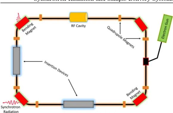
At synchrotron radiation facilities worldwide, the radiation is produced when trajectories of relativistic electrons are deflected by different magnetic struc-tures. The schematic shown in figure 3.1 highlights the basics of the gener-ation of synchrotron radigener-ation. High-velocity electrons are produced by an electron gun - a linac, or a similar device1 then injects high-velocity elec-trons into a storage ring. A radio-frequency (RF) cavity feeds energy to stored electrons to compensate for energy losses by radiation emission and helps electrons to maintain a fixed orbit around the storage ring. Other than bending magnets, the storage ring also contains some quadrupole and hexapole magnets to keep the electron beam focused.
Insertion devices are significant part of modern synchrotron storage rings. Plus providing more flexible polarization is to provide more intense radiation
1Like SOLEIL in France, after electrons are generated, enter into a booster ring, where
electrons are accelerated more until they get nominal energy, and then they are injected into the storage ring.
Figure 3.1: Schematics of a synchrotron radiation source.
compared to using bending magnets only. A usual insertion device com-prises arrays of magnets, which force relativistic electrons to oscillate instead of moving in a straight trajectory. Due to the acceleration associated with these oscillations, synchrotron radiation is produced in the insertion device. Insertion devices can be of different types, such as undulators or wigglers. In this thesis, all of the beamlines we have done our experiments are based on undulators.
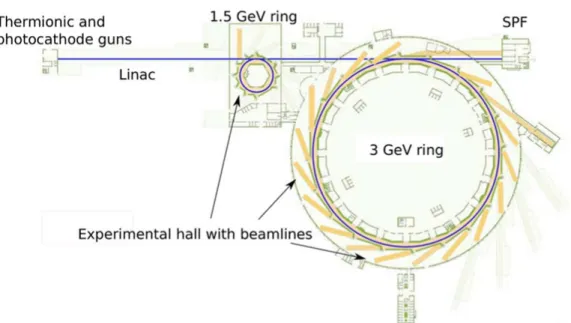
Figure 3.2 shows an overview of the MAX IV Laboratory, Lund, Sweden. The MAX IV facility consists of a linear accelerator (Linac) and two electron storage rings for the generation of synchrotron radiation. The MAX IV fa-cility Linac is roughly 300 m long and accelerates electrons to 3 GeV energy. When the Linac is not injecting electrons to storage rings, it can provide elec-tron bunches to the short-pulse-facility (SPF). Two storage rings are used to generate synchrotron radiation for a wide energy range from microwave to hard X-ray. The big 3 GeV storage ring has a circumference of 528 m and a maximum design current of 500 mA. This storage ring is optimized for the generation of high brightness hard x-rays. The small 1.5 GeV storage ring has a circumference of 96 m and a maximum design current of 500 mA. This storage ring is designed for the generation of radiation from microwaves to soft X-rays [64]. In my thesis, all the experiments were done at small storage ring.
3.2 Characteristics of Synchrotron Radiation
Figure 3.2: The layout diagram of the MAX IV synchrotron radiation facility. (Drawing by Johnny Kvistholm from MAX IV Laboratory, Sweden)
3.2
Characteristics of Synchrotron Radiation
Compared to traditional X-ray gas discharge lamps or tubes, synchrotron radiation has superior properties for characterization and probing different materials and processes at the atomic and molecular levels. Synchrotron radiation delivers a continuous energy spectrum and higher brightness. A specific photon energy can be chosen from an undulator-generated photon beam with the help of a monochromator in a wide energy range from mi-crowaves to hard X-rays. High source stability, high brilliance, and variable polarization (both linear and circular) are also different merits of synchrotron radiation, distinguishing it from traditional sources [65].These characteristics are linked to the relativistic velocity of the charged particles emitting radi-ation [66]. In this thesis, we used different characteristics of synchrotron radiation like tunability, high photon flux and high stability to study our samples from different perspectives.
3.2.1
Undulator Radiation
An undulator is a type of a insertion device consisting of two arrays of mag-nets with alternating pole separated by a gap, as shown in figure3.3. When an electron comes into the undulator, the electron starts oscillating in the plane perpendicular to the magnetic field. The distance between two magnets of the same polarity is known as the oscillation period or undulator spatial period (λu).
Figure 3.3: Working principle of the undulator. (1) magnets, (2) electron beam entering from the upper left, (3) synchrotron radiation exiting to the lower right[67]
The undulator strength parameter is estimated as follows:
K = eBλu 2πmec
(3.1)
Where e is electron charge, B is the magnetic field strength, λu is the
os-cillation period, me is the mass of the electron, and c is the speed of light.
For K 1, the small oscillation amplitude will give narrow energy bands due to constructive interference of radiation emitted at different oscillations (undulator), and K 1 will give a broad energy band due to the radiation contribution of each period summing up (wiggler) [68].
The emitted photon energy can in principle be controlled by varying the mag-nets strength, but in practice, the undulator gap is the most easily changeable parameter. By changing the magnetic arrays of the undulator, we can also change the light polarization. An example of a FinEstBeAMS beamline un-dulator spectrum is shown in figure3.4. The undulator peaks are not evenly spaced because monochromator’s contribution of diffraction orders.
3.3 FinEstBeAMS Beamline at MAX IV
Figure 3.4: An example of a FinEstBeAMS beamline’s undulator energy spectrum, measured at 45 mm gap.
3.3
FinEstBeAMS Beamline at MAX IV
Most of the experiments in this thesis were done at FinEstBeAMS2 beamline [69, 70] located at 1.5 GeV storage ring of MAX IV. The beamline has been designed to produce a wide energy range of radiation from 4.3 eV (ultraviolet) to 1000 eV (soft X-rays). The specially designed elliptically polarizing undu-lator (EPU) is used together with a plane grating monochromator (PGM). The EPU is a straight region of 2.5 m length with 25 full periods of 95.2 mm and half a period at each end. The plane grating monochromator is illumi-nated with collimated light (cPGM). To change energy during experiment, both undulator and monochromator is used, monochromator selects the en-ergy from a broad undulator enen-ergy peak. Four different mirrors from the undulator to endstation are used to focus and defocus the light at endstation. The water-cooled toroidal mirror (M1) and the plane mirror (M2) take the beam from the undulator, and most of the heat is absorbed here. The M1 and M2 mirrors collimate the beam both vertically and horizontally. The cPGM has two types of gratings, one for low photon energies (92 l/mm) and one for high photon energies (600 l/mm). The uncooled toroidal mirror (M3) is used to refocus the beam, which is dispersed after monochromator. The smallest spot size of the beamline is approximately. 100 µm × 100 µm, which is achieved by using the ellipsoidal refocusing mirror (M4). The de-tailed optics layout of the beamline is shown in figure 3.5. The total power accepted by the beamline is about 600 W. The estimated photon flux at the sample is estimated from 8 × 10¹³ photons/s to 8 × 10¹¹photons/s (between
4.3 to 800 eV) and 1012photons/s (>1000 eV). At the low photon energy,
there is some higher-order light from the undulator that can be suppressed using different kinds of filters like LiF filter for energy up to 11.8 eV and Mg filters energies from 25 to 50 eV with the low energy grating.
Figure 3.5: The optical layout of the FinEstBeAMS beamline at MAX IV. M1-M4= Mirrors, PG=Plane Grating, ES=Exit Slit, SS=Solid State, and GP=Gas-Phase. (From P¨arna R et al. (2017), Nucl. Instrum. Methods Phys. Res. A, 859, pp.85. Reproduced with permission c 2017 Elsevier B.V.)
FinEstBeAMS beamline has two branches, dedicated to gas-phase and solid-state studies. In this thesis, we have done all of our experiments at the gas-phase endstation. The gas-gas-phase endstation provides sample environments for different types of samples from single-molecule vapors to clusters. The gas-phase experiments are not appropriate for the UHV conditions necessary in the beamline, therefore the endstation also has a differential pumping sec-tion. The differential pumping section consists of three stages; a 300 l/s turbomolecular pump, a line-of-sight differential ion pump, and a 75-80 l/s ion pump. The differential pumping section helps to maintain vacuum and also protect the optics of the beamline. The gas-phase endstation has two chambers; an upstream chamber and a downstream chamber. The down-stream chamber is equipped for photo-luminescence experiments. However, we did all experiments in this thesis at the upstream chamber, consisting of a Scienta R4000 electron spectrometer, equipped with a fast position-sensitive detector for photo-electron, photo-ion (photo-ion) coincidence measurements (PEPI(PI)CO). The electron spectrometer can also be used separately for high-resolution electron spectroscopy of gas-phase samples. The time-of-flight (TOF) spectrometer capable of multi hit momentum imaging is also part of the upstream chamber. As per requirement, the ion spectrometer is removable and can be stored at a separate storage chamber. The endstation
3.4 Sample Delivery Systems
interaction chamber is rotatable around the beam axis of the beamline from the Scienta spectrometer’s horizontal to vertical position under vacuum. This rotation is beneficial in combination with selecting the polarization plane of the helical undulator. The rotation is also beneficial for access to a larger port easily for mounting some specialized equipment, for example we in-serted a resistive oven from that larger port to introduce the sample inside the chamber3. A custom made software is developed to communicate between the TOF spectrometer and electron spectrometer for PEPI(PI)CO studies in gas-phase. The ion and electron coincidence acquisition is performed using the CoboldPC software. In Papers I & II all experiments are done at the FinEstBEAMS beamline.Figure 3.6 shows a drawing of the GPES and red arrows indicates the important components of endstation.
Moreover, in Paper III of this thesis, we used similar beamlines for different experiments. We used the PLEIADES4 beamline at SOLEIL synchrotron ra-diation facility, Paris, France, to study nanoparticles by XAS in TEY mode. We also used the FlexPES5 beamline at MAX IV synchrotron facility, Lund, Sweden, for liquid-jet XAS studies in PEY mode.
3.4
Sample Delivery Systems
3.4.1
Vapor Production
At room temperature and pressure, many organic compounds are solid. Elec-tron and ion spectroscopy of free molecules of such organic samples need some method to produce isolated molecular vapor. One of the easiest ways to pro-duce vapor is to heat the material as the vapor pressure of material increases with temperature. For the low-temperature vapor production of the organic sample, a resistive oven has been used. Our research group designed this resistive oven at the University of Oulu. The schematics of the oven is shown in figure 3.7.
In this oven, a resistively heated wire is encircled around a crucible. The crucible is heated by thermal conduction and radiation. During the heating, most of the heat losses are by radiation. To minimize heat losses, special heat shields can be used. There is the option to use water cooling for extra cooling, but in this thesis, we did not use that because our temperature is not that high during the experimentation. In the experiments of Papers I & II, stainless steel crucibles were used. We monitored the TOF mass spectra as function of temperature to detect any thermal sample deterioration, and
3Figure3.6a shows the overall drawing of endstation in chapter 4
4Polarized Light source for Electron and Ion Analysis from Diluted Excited Species 5Flexible Photo Electron Spectroscopy
Figure 3.6: The main componant of Gas-Phase End Station(GPES) at FinEstBeAms Beamline at MAX IV, Synchrotron facility, Sweden. Main components labelled with red arrows. (From Kooser K. et al. (2020), J. Synchrotron Radiat., 27, pp.1082. Reproduced under CC-BY 3.0)
established a suitable working temperature before the actual measurement.
3.4.2
Free-Standing Nanoparticles Preparation
In Paper III, free nanoparticles were prepared from hydrated conditions (from solution form) by a constant output atomizer (N◦ 3076, TSI Inc) [71]. Then these generated hydrated nanoparticles are dried by diffusion-based silica driers (model 3062, TSI Inc) [72] at different relative humidity (RH) levels ranging from 11% to 85%. Afterwards, these dried nanoparticles were passed through an aerodynamic lens (ALS) to the interaction chamber, as shown in figure3.8.
The constant output atomizer is used to atomize different solutions and sus-pensions. The compressed gas, also known as the carrier gas, is expanded through an orifice to form a high-velocity jet. Through the vertical passage, the solution is brought near the atomizing section, then atomized by the jet, and coarse particles are impacted on the wall opposite to the jet. This way, the impacted particles drain back to the solution container at the atomizer
3.4 Sample Delivery Systems
Figure 3.7: Schematic layout of the resistive wire oven.
assembly block. Small particles move in the opposite direction out of the atomizer.
Two diffusion dryers were used to dry hydrated salt nanoparticles. These diffusion dryers are designed as a general-purpose diffusion dryer to dry wet-particles with a slight loss of wet-particles. The inlet of the diffusion dryer is integrated to a water trap system to catch the coarse particles. The dryer consists of two concentric cylinders; the drying agent, silica gel, is placed between the acrylic outer cylinder and wired screen cylinder. As the hy-drated particles pass through the inner cylinder, the water diffuses through the wired cylinder to silica gel. The particle has no direct contact with the silica gel; therefore, the particle loss is minimum. The silica gel can be reused after drying in an oven.
After the nanoparticles are dried by the diffusion dryer, the nanoparticle beam enters the ALS. As we generated salt nanoparticles at atmospheric pressure, the ALS allows us to transfer these nanoparticles from atmospheric pressure into the vacuum chamber. The sequential compression and ex-pansion of carrier gas through a series of coaxial orifices with different di-ameters help focus the beam of nanoparticles into the interaction chamber. The nanoparticles will separate from the gaseous streamlines after passing through the orifices in the ALS and get focused along the lens symmetry
Figure 3.8: Schematic diagram to illustrate generation of free-standing nanoparticles beam. (From Abid A. R. et al. (2021), RSC Adv, 11, pp.2104. Reproduced under permission CC-BY 3.0.)
axis by the inertia effect. Figure 3.8 shows the overall representation of nanoparticles generation with the atomizer, drying, and transferring into the interaction chamber.
Using this system we can get particles of a broad size distribution (average diameter of 100-200 nm range) from hydrated condition into a sub-millimeter sized beam inside the interaction chamber.
3.4.3
Liquid-Jet
A liquid-jet setup is used to study different volatile liquids. The liquid-jet was first employed by Faubel et al.[73] in 1988. The liquid-jet is produced when a sample solution is pushed with a constant flow rate (∼0.5-1 ml/min) through a converging quartz glass capillary, known as a liquid-jet nozzle. The nozzle opening size is typically ∼20-25 µm, determining the size of the jet produced at the rip-off-point6. PEEK tubing and filters7 are mostly used during experiments. There are three different regions of the liquid-jet: (1) After rip-off, the jet has a laminar flow (for ∼5-10 mm).
6The point where the nozzle opens in the vacuum chamber.
3.4 Sample Delivery Systems
(2) Then it changes into a turbulent flow.
(3) Eventually, the flow disintegrates into diffuse droplets.
Figure 3.9: Schematic to illustrate liquid-jet setup at VERITAS beamline, MAX IV Laboratory, Sweden.(SR=Synchrotron Radiation)
The jet temperature decreases by evaporative cooling after entering into the vacuum of the experimental chamber [74]. The jet cooling rate is not very well known because of the cut-off in the maximum radial ablation rate. Therefore, it is difficult to predict the temperature of the jet surface. In Paper III, the liquid-jet used has no sample disposal, but the sample is caught in the liquid nitrogen trap and cannot be recycled. During my doctoral research secondment at VERITAS beamline, MAX IV Laboratory, Sweden, I partici-pated in the commissioning of the liquid-jet setup, which has a unique sample catcher for recycling samples and a degasser (DEGASi PLUS Semi-Prep 4-ch 925 µl). Figure 3.9 illustrate the simple schematic of liquid-jet setup at VERITAS beamline. The liquid-jet setup at the FlexPES beamline used in Paper III is quite similar to the VERITAS beamline, excluding the catcher system.
CHAPTER
4
Spectroscopic Methods and
Data Handling
In this thesis, photoelectron spectroscopy (PES), ion time-of-flight mass spec-troscopy (ion TOF-MS), and photoelectron, photoion, (photoion) coincidence spectroscopy (PEPI(PI)CO) were used to study the photofragmentation of the biologically relevant molecules in the gas-phase (Paper I & II). X-ray absorption spectroscopy (XAS) was used to learn about changes in the lo-cal environment of ions in differently hydrated nanoparticles (Paper III). All the experiments were performed with synchrotron radiation, at MAX IV and SOLEIL. Extreme ultraviolet (XUV) or soft X-ray radiation was used to ionize the samples.4.1
Electron Spectroscopy
Electron spectroscopy is based on the photoelectric effect observed by Hein-rich Hertz (1887), and later on, this effect was utilized in photoelectron spec-troscopy, pioneered by Kai Siegbahn and co-workers [75] in X-ray regime, and David Turner and coworkers in ultraviolet regime[76]. PES has gained much importance in the characterization of different types of matter. After interaction with photons, an ionized molecule or an atom emits electrons carrying plenty of information about the molecular electronic structure. The binding energy is very sensitive to the chemical environment of the molecule. The chemical environment is related to the identity, number, and distance of these adjacent neighbors atoms. The intrinsic factor related to the chemical environment is the charge state. The change in the binding energies caused by changes in chemical environment is called chemical shift [77]. This prop-erty is used in chemical analysis by core-level photoelectron spectroscopy. Valence orbitals participate in bond formation; therefore, chemical shifts are challenging to interpret [32,77].
Auger spectrum provides information about the multi-ionized molecule’s fi-nal states, and the core-level photoelectron spectrum can reveal much
in-formation about the molecular structure, for example number and relative abundance of different functional groups. In all cases, the analysis starts by measuring the kinetic energy of the electrons. The most used electron spectrometers today has a hemispherical deflection electron analyzer (HDA) as an electron energy analyzer. The simple cut-through diagram1 of an HDA is shown in figure3.5. In this thesis, all the electron spectra were measured with the help of an HDA.
Figure 4.1: Simple cut-through diagram of a hemispherical electron energy analyzer (HDA).
There is a lens system at the HDA entrance to collect and guide the emitted electron towards the entrance slit of the hemisphere. The electrons can be accelerated or deaccelerated by changing the electric potential of the lenses. The primary function of the lens system is to increase the transmission2. The central part of an HDA consists of two concentric hemispheres acting as electrodes at different potential. The electrons follow a curved path due to the electrostatic force. The average or nominal radius (ro) of the spheres
determines the resolution of the analyzer and the kinetic energy dispersion window of the electrons, in combination with the pass energy and the slit width. The applied electric field between the two electrodes of the analyzer will determine the path of the electron with specific kinetic energy (Eo) along
the nominal radius (ro). Slightly different energies around Eo follow different
paths through the analyser, and hit the detector at different positions. The HDA focuses electrons of the same energy entering from different angles to
1Concept adopted from technical presentation from Vohs J. et al., University of
Penn-sylvania, USA (2006).
4.1 Electron Spectroscopy
the same x-coordinate of the detector. The transmission of an HDA is de-fined by the solid angle of acceptance of an analyzer; larger acceptance angle means an increased transmission.
To calculate the constant relative resolution of HDA, following approximate formula can be used:
∆E
E =
s1+ s2
2ro
(4.1) In the equation 4.1, s1 and s2 are the entrance and exit slit widths,
respec-tively, and rois the nominal radius of the analyzer, as shown in figure4.1. For
the position-sensitive analyzer, the width of the exit slit can be substituted with the accuracy of the detector. In addition to that, position-sensitive an-alyzers improve the intensity because electrons can be collected from a larger area.
The HDA can also be operated with constant absolute resolution (∆Ea),
which is more practical for photoelectron spectroscopy. To achieve a good absolute resolution, high kinetic energy electrons are challenging, and there-fore the electrons are retarded bethere-fore entering in the HDA analyzer to over-come the problem. The pass energy is the actual energy of the electrons after the retardation.
The simple formula for calculating the constant absolute resolution is the following:
∆Ea = Epass.
s1
2ro
(4.2) We can adjust the resolution and transmission by changing the pass energy and/or width of the entrance slit according to the experiment’s requirement. For the measurement, resolution and transmission are critical. These two parameters contradict each other, like increasing resolution (by decreasing width of entrance slit and pass energy), resulting in the decrease in the transmission of electrons and vice versa [78].
When using the electron spectrometer in the coincidence mode, the commu-nication between the electron and TOF spectrometers should be fast, which is achieved by using micro channel plates (MCPs) and a resistive anode [79]. The electron output signal has a much shorter delay than the actual electron arrival time with the resistive anode detector (RAD). The resistive anode is placed on behind the MCPs, which enhance the electron signal by multiplying each electron hit due to an avalanche effect, as in figure 4.2. When the high energy primary electron hits the micrometer-sized holes of the MCP coated with a material with a low work function, secondary electrons are created, and the electron avalanche reaches then the anode. The signal propagates
to each corner of the anode. By measuring the signal’s attenuation from each corner, the hit’s position can be measured. The HDA at FinEstBeAMS beamline has three MCPs in a Z-stack configuration and a resistive anode [70].
Figure 4.2: Schematic diagram for the detection of an electron at the MCP detector and a resistive anode. (From Rogers A. M et al. (2015), Nucl. Instrum. Methods. Phys. Res. B, 795, pp.327. Reproduced with permission
c
2015 Elsevier B.V.)
During the coincidence measurements, we used fixed voltages on the HDA. Therefore only electrons from a fixed kinetic energy range were collected. In our HDA type of spectrometer, the kinetic energy window size is roughly 10% of selected pass energy, but depends on the size of the detector in relation to the dispersion of the analyzer. In our measurements, we selected 100 eV pass energy, resulting in an electron kinetic energy window is approx. 10 eV. In the coincidence setting, the HDA is not able to measure the electron energy directly. The software gets only the hit position of the electron in the direc-tion of the electron energy dispersion. The measurement software does not know the connection between the hit position and the energy; therefore, it was done after the measurement with some absolute standard, carbon dioxide (CO2) in our case. The photoline is moved across the detector by changing
the incident photon energy, and then the known kinetic energy vs. detector position is fitted to a second-order polynomial of measured points.
4.2
Time-of-Flight Mass Spectroscopy
In ion time-of-flight mass spectroscopy (ion TOF MS), ions with different mass-to-charge ratios (m/q) are separated based on the flight times between some start pulse (triggered for example by electron detection) and the arrival