Mechanical properties of trabecular
structures produced by SLM, as a
function of the trabecular morphology
PAPER WITHIN Product Development and Materials Engineering AUTHOR: Frida Johansson & Johanna Klarin
TUTOR: Alberto Molinari JÖNKÖPING June 2017
Date: 2017-05-24
Abstract
Eurocoating, Italy, is a company that works in the biomedical sector. They have for a long time created prostheses from CAD files achieved from customers, and now they want to build their own expertise about the design. The thesis work was a part of a three year long collaborative research project between Eurocoating and University of Trento that was aiming to investigate the prostheses with open-porous surface and trabecular structure, created by Selective Laser Melting.
The purpose of the thesis was to investigate and characterize 30 different trabecular structures of Ti-6Al-4V, fabricated by Selective Laser Melting. That includes
investigation the effect on the morphology and porosity fraction caused by the
manufacturing and the effect on mechanical and physical properties due to the different characterizations of the structures.
The thesis work had its foundation in literature studies to receive deep knowledge about the subject. Practical tests were performed to investigate mechanical behaviour under compressive and tensile loading, static friction and wear resistance. The findings from these tests were compared to the porosity fraction and the morphological
characterizations.
The result stated that the porosity fraction was lower than the designed porosity, and that is was strongly influenced by size of the voids and struts. The strut thickness was higher than the design values, especially on the lateral surface, while the voids size were approximately as designed. Result from the compression test showed a trend of
decreasing stiffness and strength with increasing porosity fraction. Also structures with same porosity fraction could have a wide range in mechanical properties which
indicates high dependence on the morphological geometry i.e. pore size and shape, strut size and pore distribution. Comparisons between tensile and compression behaviour stated that the structures had a lower strength but a significant higher stiffness in tensile load. All structures from the wear test showed a good resistance while the results from the friction test needs further investigation to be fully understood.
The physical and mechanical properties of the trabecular structures was found to be close to those of cortical and trabecular bone in porosity, stiffness and strength. There is a range of variations leading to possibilities to adopt the application depending on customer. Thus, these can be considered as promising structures used biomedical application to optimize osseointegration and secondary long term fixation.
Keywords
Additive Manufacturing, Selective Laser Melting, Ti-6Al-4V, Trabecular structure, material testing, mechanical properties
Surface technology
Gianluca Zappini, Valerio Luchin and Emanuele Magalini
The project group at Eurocoating
A special thanks for giving us this opportunity and for providing us with all the specimens and their expertise in the subject.
Matteo Benedetti
Associate Professor
Mechanical design & machine construction
For helping us with the set up and knowledge about the compression and tensile tests.
Vigilio Fontanari
Professor
Mechanical design &machine construction
For helping us to find a appropriate method to perform the friction test.
Lorena Maines
Laboratory technician
Department of Industrial Engineering
For helping us with the morphological investigation in the SEM.
Luca Benedetti
Laboratory technician
Department of Industrial Engineering
For all help with the morphological and microstructural analysis.
Massimiliano Tomaselli
Research assistant
Department of Industrial Engineering
Our guide and teacher in the laboratories, our helper when we needed something practical and our company during many pleasant “fika” breaks.
Alessandro Dai Pré and Nicola Zambaldi
Students at University of Trento
For helping us with the morphological investigation in the stereomicroscope.
And all others that in some way helped or guided us through this thesis work. It wouldn’t have been possible without you and we are really grateful! Thanks also to University of Trento for the office with a view and for the access to the facilities. We also want to thank everyone that made sure that we got an amazing experience during our exchange semester in Italy, including tips about places to visit and
restaurants to eat at. A special thanks for teaching us how to drink espresso and how to properly serve red wine. It will not be forgotten.
We also want to thank Salem Seifeddine, professor at Jönköping University, for helping us to search for an interesting thesis work all around the world and to fulfil our dream to go abroad.
Contents
1
Introduction ... 1
1.1 BACKGROUND ... 1
1.2 PURPOSE AND RESEARCH QUESTIONS... 1
1.3 RESEARCH APPROACH... 2 1.4 DELIMITATIONS ... 3 1.5 OUTLINE ... 3
2
Theoretical background ... 4
2.1 TRABECULAR STRUCTURE ... 4 2.1.1 Pore architecture ... 4 2.1.2 Biomedical division ... 52.2 SELECTIVE LASER MELTING ... 6
2.2.1 The process ... 6
2.2.2 Characteristics ... 6
2.2.3 Sustainability perspective ... 7
2.3 TI-6AL-4V ... 7
2.3.1 Composition and microstructure ... 7
2.3.2 Mechanical behaviour ... 9
2.4 PREVIOUS RESEARCH IN THE FIELD ... 9
3
Method and implementation ... 12
3.1 PRELIMINARY WORK ... 12 3.1.1 Porosity fraction ... 12 3.1.2 Morphological analysis ... 12 3.2 SPECIFICATION OF SPECIMENS ... 13 3.2.1 Batches ... 13 3.2.2 Structures ... 14
3.2.3 Porosity fraction, microstructural analysis, compression test and morphological analysis ... 15 3.2.4 Friction test ... 16 3.2.5 Tensile test ... 16 3.2.6 Abrasive test ... 17 3.3 METHOD PLANNING ... 17 3.4 PHASE Ⅰ ... 18 3.4.1 Porosity fraction ... 18
3.5.3 Abrasion test... 31
4
Findings and analysis ... 33
4.1 PHASE Ⅰ ... 33 4.1.1 Porosity fraction ... 33 4.1.2 Microstructural analysis ... 34 4.1.3 Compression test ... 35 4.1.4 Morphological analysis ... 42 4.2 PHASE Ⅱ ... 44 4.2.1 Friction test ... 44 4.2.2 Tensile test ... 45 4.2.3 Abrasive test ... 48
5
Discussion and conclusions ... 50
5.1 DISCUSSION OF METHOD ... 50 5.1.1 Preliminary work ...50 5.1.2 Porosity fraction ...50 5.1.3 Compression test ...50 5.1.4 Morphological analysis ... 51 5.1.5 Friction test ... 52 5.1.6 Tensile test ... 52 5.1.7 Abrasive test ... 52 5.2 DISCUSSION OF FINDINGS ... 53 5.2.1 Porosity fraction ... 53 5.2.2 Compression test ... 53 5.2.3 Morphological analysis ... 55 5.2.4 Friction test ... 56 5.2.5 Tensile test ... 56 5.2.6 Abrasive test ... 57 5.3 CONCLUSIONS ... 57 5.4 FUTURE WORK ... 59
6
References ... 61
7
Search terms ... 64
8
Appendices ... 1
Jönköping University, School of Engineering.
1.1 Background
Eurocoating is a company that figures in the biomedical sector. The company specializes in biomedical surface treatments and creating and developing new surface solutions for orthopaedics, dental, trauma and spinal applications [1].
Eurocoating is now producing prostheses with additive manufacturing technologies from CAD models received from their customers. The company has deep knowledge about additive manufacturing, and now they want to build their own expertise about the design of the prostheses. This to be able to help their customers to choose the right product for their specific need and to have a product range to offer. One of the areas that Eurocoating wants to investigate is the prostheses with open-porous surface and
trabecular structure, created by Selective Laser Melting. This kind of structure is highly beneficial for secondary fixation (long term fixation) of orthopaedic prostheses. The pore architecture is one of the important points to make the product optimized for osseointegration (the formation of a direct interface between an implant and bone, without intervening soft tissue) and is also of importance to get the right stiffness on the material. This trabecular structure will affect the mechanical properties of the products. When it comes to the biomedical area there are many requirements in terms of ISO and ASTM standards of mechanical and physical properties such as wear, static friction and compression for the product to fulfil. It is therefore of importance to have knowledge about how a trabecular structure created by Selective Laser Melting affects the different properties. It is this area of investigation that is the scope of the thesis.
1.2 Purpose and research questions
To achieve knowledge about the topical area, the thesis work aimed to investigate and characterize specimens with different trabecular structures, fabricated by the additive manufacturing method Selective Laser Melting. The effect on mechanical and physical properties due to the porosity fraction and morphology of the structures was
investigated.
To increase that knowledge the following research questions were established to be answered during the thesis:
How do the different structures with same porosity fraction manufactured by Selective Laser Meltinginfluence the mechanical properties?
What is the correlation between Young’s Modulus and the porosity fraction?
Is there a correlation between compression strength and wear resistance measured by the Taber test?
Is the static friction coefficient affected by the porosity fraction?
Can the morphological characteristics of the specimens be defined through a metallographic approach on the surface?
Is the porosity fraction different between the designed values and the real values of the structures?
To answer the determined research questions a suiting research approach was to be considered.
1.3 Research approach
The thesis work was a part of an experimental research project, therefore the
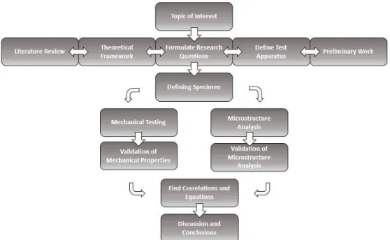
approached positivism was used. Positivism is based on deductive reasoning together with hypotheses testing and is related with quantitative methods. In this thesis the positivist researched design described in the book Research methods for students, academics and professionals [2]is modified to the thesis work so the hypotheses is replaced by research questions. Figure 1 shows an illustration of the research approach used in this thesis.
Figure 1. Illustration of the research approach used in this thesis
Initially a meeting with Eurocoating was arranged to acquire information about the company's objective of the research project and to understand the purpose of the thesis. The literature review was restricted to previous research in the area of importance and was the base for the theoretical framework (chapter 2). With knowledge about the trabecular structure, Selective Laser Melting and material properties the research questions could be formulated and with good complement of experienced personnel the test apparatus was defined. The preliminary work was for practice on metallography and also to validate and learn the mechanical test machines by personal instructions. The mechanical and physical test procedures were determined by standards or after literature search. The results were analysed, discussed and conclusions were drawn. A full list of the literature can be found in chapter 6 and the people giving instructions are credited in acknowledgement.
used in the SLM process were kept confidential and were therefore not taken into consideration in the analysis. The mechanical and physical properties tested and analysed were density, wear resistance, static friction coefficient and compressive and tensile behaviour. Majority of the tests was performed and analysed according to standards. The microstructural and morphological analysis was limited to porosity fraction, void and strut size and determination of the presence of ꞵ phase. The result from the tests was only used for analyses and to find correlations between the porosity fraction, morphology and different properties.
1.5 Outline
The thesis begins with a theoretical background where the reader will be introduced to subjects that were of importance for the thesis work. There will be an introduction to trabecular structure and Selective Laser Melting and there will also be a description of the material used and previous research in the field.
Following the performance of the used methods will be described. For the tests that had a standard to follow there will be a definition of the standard and then how it was adapted to fit the thesis work. Further there will also be a review of the result. A deeper analysis of the result can be found in the subsequent chapter.
The thesis will be closed with a discussion of the methodology used and the findings of the thesis, a brief summary of the main points in the thesis work and propositions for further research.
2 Theoretical background
This chapter describes the theories and previous research found in the literature that covers the subjects of this thesis. The trabecular structure and its pore topology and how the structure affects the mechanical properties is first presented followed by information about Selective Laser Melting, the material used; Ti-6Al-4V and last previous research.
2.1 Trabecular structure
Trabecular bone is the inner part and the cortical bone is the outer part of the natural bone, they belong to porous materials with interconnected voids [3]. The trabecular bone is found in the vertebral bodies of the axial skeleton and at the end of the long bones of the appendicular skeleton. It has a porous structure pattern. This complex patterns assists to maximal strength for minimum mass for the skeleton. The trabecular network has both rod-like and plate-like structures with interconnected voids, which has a random structure and can be found in more or lesser proportion depending on the skeletal site. The trabecular bone provides, due to high mineral surface area, an
extensive substrate on which cellular interaction with bone mineral material can occur [4].
Figure 2. 3D CAD model of trabecular structure [4].
2.1.1 Pore architecture
With additive manufacturing it is possible to obtain similar design, which is
interconnected pores as natural bone i.e. pore size and pore distribution (Figure 2). Titanium is known for its good biocompatibility since decades and it is already used as material for medical implants. In form of a trabecular structure it can lead to the development of innovative orthopaedic prostheses [3]. The morphology of porous materials can be both stochastic (random) and ordered (regular) depending on the manufacturing settings [5]. The trabecular structure has an open-cell structure, meaning it is permitting flow of fluid inside the scaffold, the other type of porosity is closed-cell porous, that can be found inside the structure, i.e. it cannot permit flow of fluid [6]. There are criteria that porous biomaterials should be able to achieve for bone
replacement. These criteria include: filling of bone defect voids, the pore architecture and the pore interconnectivity should promote osseointegration and sufficiently good mechanical properties to support physiological loading. The function of the porous biomaterial structure needs to consider the microarchitecture like pore shape and size, cell topology and porosity fraction, both of these have a high impact on the
osseointegration, interface strength and mechanical behaviour. For optimal osseointegration the pore size should be between 50 μm and 800 μm and have a porosity higher than 50% [7]. With a porosity of 75% to 80% an increase in fixation strength can be obtained and it is needful to have interconnectivity between the pores in order to permit osseointegration [8]. There are limits of the pore size due to the
biological factors, pores larger than 700 μm can promote osseointegration but at reduced rates and volumes of bone ingrowth. Pore size less than 100 μm loses the
Figure 3. Orthopedically hip prostheses with trabecular structure [1].
Full dense Ti-6Al-4V has a yield stress of approximately 871.5 MPa [11] and an elastic modulus of 110 GPa[3]. Cortical and trabecular bone has compressive strength of 17-209 MPa [4][12] and the elastic modulus of full dense Ti-6Al-4V is 5 to 200 times higher than for natural bone, that is ranging from 0.5 to 20 GPa. With a trabecular structure of the prosthesis it is possible to avoid mismatching of elastic modulus thus keep away from the phenomena “stress shielding”. Stress shielding is uneven stress distribution between the orthopaedic prosthesis interface and the bone that can lead to bone
resorption around the prosthesis and eventually a high risk for fracture and loosening of the prosthesis [3]. There is evidence that bone responds to mechanical stress-strain stimuli, that below a specific stress-strain threshold, the bone receives a lesser need for remodelling. Remodelling in this context means changes in the trabecular bone
orientation and density. This can lead to increased bone resorption levels. On the other hand, increased bone formation can be found by an increase of mechanical stimuli in the specific area [13].
A strong interface reduces the risk of tissue strain and micromotion, thus also support the osseointegration. Shear stress is a measure of the maximal interface loading capacity and need to be considered due to the physical loading [14]. Also for the orthopaedic prosthesis it is important to have a sufficiently high friction coefficient so the bone will enhance initial steadiness with low micromotions at the interface. The stability will encourage and maximize the osseointegration and conduce to mechanical interlock of the prosthesis and ideal mechanical stability [8].
The orthopaedic prosthesis need to have good wear properties to resist particle
shedding. This particle shedding is undesirable and can occur during surgical procedure of an orthopaedic prosthesis or as outcome of the micromotion caused by the prosthesis after insertion. If the micromotion can cause weight loss this can result in a third body wear of articulating surface which is highly undesired [15].
2.1.2 Biomedical division
A biomaterial is a synthetic or natural material intended to interface with a biological system [3]. Porous biomaterials constitute a smaller subsection of the whole field of biomaterials and are particularly relevant for bone interfacing components. This since they provide a high surface area for bone ingrowths and also for secondary long term biologic fixation in orthopaedic and dental bone implant applications. Thus greater
accentuation on physiological solutions in the biomedical section of orthopaedic devices has led to more focus on the integration of porous structures. Previous studies have shown that trabecular structures can be designed both as the natural structure and with similar mechanical properties of bone compared to full dense counterparts [16].
2.2 Selective Laser Melting
Additive manufacturing, AM, is a technology where an object is created by adding material in layers. The cross sections of the object are obtained from a 3D CAD file. All the current AM processes uses this technique, the way they are different from each other is in how the layers are created and bonded to each other and in what materials that can be used [17].
Selective Laser Melting is one of three different types of Laser Additive manufacturing processes, where a laser is used to bond the layers to each other. The other two processes are Selective Laser Sintering and Laser Metal Deposition [18].
2.2.1 The process
Selective Laser Melting, SLM, is a technique where loose powder material is melted and joined one layer at a time by an infrared fiber laser. The procedure is performed through several steps. First a thin layer of metal powder is distributed on a process platform. Secondly the laser melts the metal powder line by line in the selected areas. When the first layer is finished a new layer of powder is distributed upon the first one and melted by the laser. This procedure is repeated for multiple additive layers [19]. During the process inert gas is used to reduce metal powder oxidation and keep oxygen content into a required standard. In SLM a complete melting/solidification mechanism is used unlike Selective Laser Sintering where the powder is only partial melted. When using this technique the laser beam size and the scan speed is of importance of the duration of the beam on the particles [18].
The SLM system consists in general of a sealed building chamber, laser, automatic powder layering apparatus and computer system for process control. There is also extra mechanism as gas protection system and powder bed preheating system (Figure 4) [18].
Figure 4. A Selective Laser Melting system [18].
2.2.2 Characteristics
SLM makes it possible for any 3D object to be created, it reduces waste material and it saves energy in comparison to traditional manufacturing techniques. Thus has it an
2.2.3 Sustainability perspective
The AM process has several sustainability benefits, both in the environmental and the economical point of view. One reason for that is the reduced material waste [22], [23], [24]. The waste could be reduced with up to 90% in comparison with traditional
subtractive manufacturing processes [24]. AM processes are also beneficial since the life cycle material mass and energy could be reduced. Another point is that the
manufacturing could be made in multiple locations. That makes it possible to have the manufacturing closer to the point of consumption which leads to a reduction in
transportation, meaning a minimised used of freight and lower fuel burden which has an impact carbon footprint and overall energy consumption. Also the part weight can be minimized [25], which means more light weighted transports. Other beneficial points are that it allows complex geometries to be produced [24] and products to be optimized for its function [22].
In the economical point of view AM processes are beneficial since there is no need for tooling which reduces the ramp up time and also the expenses. It is quick and easy to change the design of a product which also is of advantage for design customization. The supply chains can be made simpler which leads to shorter lead times and a smaller amount of inventories [22], [24].
2.3 Ti-6Al-4V
The material used in this research project was the Titanium alloy Ti-6Al-4V, also called Ti64, which is one of the most widely used Titanium alloys [26], [27]. Ti-6Al-4V is used in multiple applications in medical industry since the alloy has an extraordinary biocompatibility, particularly in contact with bone or tissue. Except for the biomechanical sector Ti-6Al-4V is also used in the aerospace industry, chemical industry, gas turbines and marine applications [27].
2.3.1 Composition and microstructure
Ti-6Al-4V is a composition of Titanium (Ti), Aluminium (Al) and Vanadium (V). The composition of the alloy is approximately 6 wt% Al and 4 wt% V [21]. The material can also contain small amounts of Oxygen (O), Hydrogen (H), Carbon (C), Nitrogen (N) and Iron (Fe). In Europe the maximum composition of these substances is around 0.2 wt% O, 0.0125 wt% H, 0.08 wt% C, 0.05 wt% N and 0.3 wt% Fe. The more alloying elements that is added to the Titanium the higher the strength of the material [28]. The material consist of ⍺ and phase, but Ti-6Al-4V parts created by SLM consists of ⍺ and
martensitic ⍺’ phases and the phase is missing. This is probably due to the high cooling rates. The microstructure is lamellar where the ⍺ phase is coarse and the ⍺’ phase appears as dark needles [26] (Figure 5).
Figure 5. Microstructure of Ti-6Al-4V with 3 different magnitudes [27].
In the microstructure of Ti-6Al-4V elongated laths filled of needle shaped martensitic ’ can be found in the building direction. This is a result of the SLM process. When the laser melts the metal powder it also melts underlying layers. When the grains melts they solidify and grow in the same direction as the heat conduction. When the laser moves away the ’ laths fill the prior elongated grain [19]. A heat treatment can be used to allow the microstructure to precipitate into a more stable lamellar + structure [29].
Crystallography
The and phases has different crystal structures, has an HCP structure while has a BCC structure. ’ has like an HCP structure [21]. HCP (Figure 6 b) is a Hexagonal Closed-Packed structure and BCC (Figure 6 a) is a Body Centered Cubic structure [30]. In pure Titanium the transformation from to ’ occurs easily and cannot be suppressed, therefore the transformation is believed not to be diffusion controlled but a diffusionless martensitic transformation. There is a considerable difference between properties generated from a hexagonal structure and a cubic structure. In the hexagonal structure the plastic deformation properties are much more directional than in cubic structures. This is due to the amount of closed-packed planes that the different crystal structures allow. In HCP there is only one closed-packed plane, while it in cubic crystals a higher amount of closed-packed directions is allowed [31].
Figure 6. BCC and HCP crystal structures [30].
2.3.2 Mechanical behaviour
Ti-6Al-4V is an alloy that has a very good balance of strength, ductility, fracture properties, and fatigue [32].
Ti-6Al-4V objects that are manufactured by SLM are generally strong but have a poor ductility and a certain amount of anisotropy [19]. They also usually have a lower toughness and fatigue strength in comparison to wrought components [28]. Postprocessing methods can be used to find a better balance between strength and ductility and to get properties more similar to Ti-6Al-4V produced by a conventionally manufactured material [19]. When using a heat treatment, either stress relief or hot isostatic pressing, the ductility improves, though the strength decreases [29]. A heat treatment should be done for objects exposed to fatigue [27].
2.4 Previous research in the field
There is a significant amount of previous research on Ti-6Al-4V trabecular structures manufactured by SLM and how it affects mechanical and physical properties, though the research is mostly focused on regular structure and not on irregular and fully random structures. There is also research in the biomedical perspective, i.e. the effect of pore size on bone ingrowth.
In the biotechnical area there can be seen the interest of using an open- porous structure for orthopaedic prostheses is of high rate increasing and a lot of scientific researches confirm this trend. This interest to involve the osseointegration into the trabecular structure, but also to reduce the stiffness of the material that have been connected to early prosthesis loosening due to stress shielding. It is now confirmed that the design of the pore architecture should match the mechanical properties of natural bone to reduce the risk for stress shielding [33]. The challenge is to find the optimal pore architecture in the orthopaedic prostheses to maximize both biological and mechanical performances. There is lack of knowledge and understanding the role of what the pore architecture, i.e. porosity, pore size, pore distribution as well as strut thickness, plays in the
mechanobiological response for a trabecular structure [7]. Also to have complete control over the fabrication of the pore architecture needs to be and are under development. There is also a need to have precisely control over the position of the pores in the specimen, its interconnectivity, shape and size [33].
Research on how the trabecular structure affects the mechanical and physical properties of a material has previously shown that stiffness and strength of the lattice decreases with increasing porosity. This may however vary between different topologies, i.e. it has been detected in a study that for Tetrahedron unit cell the stiffness and strength keeps decreasing with an increasing porosity while for Octet basic cell the decrease in strength ends when the porosity reaches approximately 75% [7]. There has also been indicated the size of the unit cell is of importance,the larger the unit cell, the higher the decrease
of stiffness and strength [34]. Several studies have found that different topologies affect the mechanical properties in different ways [35], [10], [7]. The fatigue behaviour is a complex function that is affected by the type of repeating unit cell, and other factors like unit cell size, porous structure and porosity [35]. Also the deformation and failure mechanisms change by the different unit cells. This can be seen particularly when the plateau region in a stress-strain has been reached, e.g. by the ratio of plateau stress to yield stress. For some structures the ratio is more or less constant while for other structures the ratio increases noteworthy with a decrease in porosity. There has also been shown that the relative density is affecting the stress-strain curve of an object, e.g. by a decreased level of fluctuations after the plateau region as the relative density increases [10]. Irregularities caused by the AM process are found to weaken the structures, both considering the fatigue strength and Young's Modulus [35].
Under compressive strain it is proved that bending and buckling modes are peculiar to porous materials consisting of cell struts. In general specimens with a high porosity deform by bending and buckling and specimens with a low porosity deform by yielding. In curves obtained from compression tests in a previous study it has been found that a decrease in the porosity fraction leads to an increase in stress. The curves of specimens with higher porosity fraction showed three clear deformation regions: first an elastic region followed by a plateau region where the specimens deform under a more or less constant stress, and thereafter a densification region. In the last region the stress increases abruptly to a higher strain. The densification region appears at a higher strain interval for the specimens with higher porosity. Though, it was also shown that curves from specimens with lower porosity did not show clear plateau and densification regions. After the elastic region these two regions seem to emerge simultaneously [36]. In a research study on specimens of metallic foams, in comparison with specimens with regular structure it was detected that under a condition of identical specific modulus (stiffness over density) the regular structure has higher specific strength (stress at failure over density) than the foam. In this study it was also shown that the foam has finer microstructure than the regular structures. This is said to indicate that the fully random structure experiences a faster cooling during manufacturing [37].
Research that have investigate stiffness on metal foams, cortical and cancellous bone characterized from tension and compression have found marginally differences [5], [38]. Further there is experimental studies that have demonstrated a difference in
compressive and tensile strength, that tensile strength has slightly lower strength [38], [9]. The result can occur from the manufacturing process that can occasionally contain inherent weaknesses between the bonds of each layer [9].
One phenomena that has been detected in both compression and tensile test in porous structures are successive failure of individual struts in the cellular construction. The failure starts with the one strut, the weakest. This causes a fall in the measured force and after this the other cells takes together over the load again and the force increases until the next failure of the next weakest strut. The stress-strain curve have a jagged
behaviour and occurs before the ultimate failure of the specimen [10], [34].
Regarding Ti-6Al-4V and how it is affected by the SLM procedure, previous research indicates that there is a phase transformation from to ’ due to the high cooling rates as earlier described [21], [26], [19]. There is also an indication that the ’ is responsible for a decreased plane stress fracture toughness with respect to build direction in comparison to cast and wrought materials [17]. Though, the yield stress and ultimate compressive strength is higher for Ti-6Al-4V containing ’ phases than for annealed microstructures containing α+β [39], [40]. It is also shown to be higher than for Ti-6Al-4V produced by conventional processing [40]. The elastic modulus is on the other hand a property that is not particularly affected by thermal treatments [39], [40].
3 Method and implementation
The thesis project contained an essential part of practical work including morphological analysis, porosity fraction measurements and microstructural analysis. Also the
mechanical testing of the trabecular structures comprising compression, tensile,
abrasion and static friction tests. The compression test were performed according to an ISO standard. The test standards for abrasion, tensile and microstructure analysis were destined for characterizing coatings used on surgical implants. These standards were however accepted to be used also for porous structures obtained by AM since there are no standards and the porous structure has the same function as a coating of the
prostheses would have. Also the industry guidance document: “Guidance for Industry on the Testing of Metallic Plasma Sprayed Coatings on Orthopaedic Implants to Support Reconsideration of Postmarket Surveillance Requirements” has been used as a reference to the performance of the tests. Initially a preliminary work was carried out followed by two phases where the result from phase Ⅰ were thoroughly comprised by compressive mechanical behaviour of the all the structures and batches, combined with
morphological and microstructural analysis. In Phase Ⅱ a further investigation was introduced of a few selected structures with the remaining characteristics from static friction, tensile and the abrasion test. During the thesis work regular meetings with the project group from the company together with the tutor were performed to discuss and evaluate the result and make decisions about the proceeding work.
3.1 Preliminary work
A preliminary work was performed to define the test methods, the test apparatus and suitable conformation of the specimens. The methods had to be pretested on
preliminary specimens to be sure they were suitable for this project and that reliable data could be achieved before the tests were performed on the real specimens. There were not an ISO or ASTM standard for all the mechanical and physical tests. Though, preliminary test and specimens were needed to ensure the test could be performed in an accurate way and verified if the specimens were suitable for the different mechanical tests.
First the compression test and friction test was defined. These specimens were used both for the microstructural analysis and the porosity measurement. Ongoing during the project the other methods were defined and the specimens were manufactured
gradually.
3.1.1 Porosity fraction
The method for calculating the porosity fraction was determined by analysing the reliability of the result from different methods founded in the literature review. The Archimedes method was tried both with water and ethanol but it turned out that the liquid could not infiltrate all the pores. The method that became the final was to use the ratio between density of the specimen and the theoretical density of Ti-6Al-4V (4, 42 g/cm3) [9].
The preliminary part was followed by defining the batches and structures and the conformation of the specimens to be able to perform the mechanical tests with suitable specimens.
3.1.2 Morphological analysis
Concerning the morphological analysis several methods were tested to investigate how the porous structure i.e. pore size and thickness of the struts could be defined. First there was a try-out of different ways to embed the specimens in epoxy plastic to find a suitable recipe for our porous structure. Both warm and cold resin can be used. In the
microscope was determined to be used.
3.2 Specification of specimens
The methods used for testing and analysing required different kinds of specimens. To be able to analyse the test results as a function of the trabecular structure 30 different structures with specific characteristics was investigated. The parameters to be analysed were the type of structure, the size of the voids and the strut thickness.
All specimens were heat treated to eliminate the remaining stresses from the SLM process to prevent that they affect the results or deformed the specimens.
3.2.1 Batches
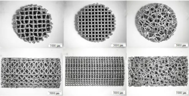
Three different batches (A, B and C) were manufactured with different morphological characteristics (Figure 7). Each batch had 10 different structures; 2 fully random, 3 irregular and 5 regular. The structures occur in all three batches but with different characteristics of strut thickness and pore size that was typical for each specific batch. The characteristics of the batches were defined as following:
Batch A - large pores, large struts Batch B - small pores, small struts Batch C - large pores, small struts
In Table 1, the values for pore size and strut thickness from the design can be seen.
Table 1. Designed pore size and strut thickness.
Batch Pore size
[μm] Strut thickness [μm] A 1500 500 B 700 200 C 1500 200
Figure 7. From left to right: Structure 1 from batch A, B and C.
The fourth possible combination would be small pores and large struts. That would however result in structures with pores that are not connected to each other and a low porosity fraction since the struts would be to large in relation to the pores to allow a structures with conected pores. This structure would not support osseointegration and was therefore not of interest for the project.
3.2.2 Structures
Each batch had 10 different structures with different morphological characteristics: regular, irregular or fully random (Table 2).
Table 2. Morphological characteristics for the structures.
Structure Type of geometry
1 Irregular 2 Regular 3 Regular 4 Irregular 5 Regular 6 Fully random 7 Regular 8 Fully random 9 Irregular 10 Regular
Regular structures means that a repeating unit cell easily could be defined while in irregular structures the unit cell is deformed, but still recognizable. In the fully random structures there were no repeating unit cell (Figure 8). The irregular structures had different grades of deformation, structure 1 had a very high grade of deformation and structure 9 had a low grade of deformation. Structure 4 had a deformation grade in between structure 1 and 9.
Figure 8. From left to right: Irregular, regular and fully random structure.
The designed porosity fraction is evaluated as the ratio between volume of the CAD model and volume of the full element. All structures in the same batch had similar designed average pore fraction but different structures could lead to differences in the porosity fraction (Table 3).
Table 3. Designed porosity for each structure in all batches
Structure Batch A [%] Batch B [%] Batch C [%]
1 75.40 78.45 92.85 2 75.60 79.99 93.21 3 70.96 80.91 94.59 4 75.59 79.68 94.16 5 76.36 80.56 94.18 6 63.31 71.96 92.39 7 49.54 59.03 90.25 8 63.52 72.20 92.36 9 78.98 82.61 94.88 10 78.99 82.82 94.98
The specimens had different size and shape for different test, this however assumed to not have affected the structures since the manufacturing process is able to create the same structure for every replica.
3.2.3 Porosity fraction, microstructural analysis, compression test and
morphological analysis
According to the ISO standard 13314 the compression specimens should have a
cylindrical (recommended) or rectangular cross-section. The specimen length should be from minimum the same to maximum twice the length of the specimen diameter or edge. The diameter or edge length of the specimen should be at least 10 times the average pore size. The design of the specimens where determined to be cylinders with approximately dimensions of 15×30 mm (Figure 9). These specimens were also used for the porosity fraction measurements, microstructure analysis and morphological analysis.
Figure 9. Specimen with dimensions.
3.2.4 Friction test
For the static friction test there was no ISO or ASTM standard that decided the design of the specimens, though there was an internal standard for performing the test. The internal test fixture did not suit for porous structures when a too large external weight should be added to reach a nominal stress of approximately 0.28 MPa [8]. This nominal stress was wanted to be able to compare the results achieved with previous research to determine if they were in a reliable range. Therefore the specimens were decided to have small proportions to be able to use lower added weight. The new text fixture were manufactured according to our requirements to fit the specimens but the procedure were remaining the same according to the internal standard. The specimens were cylinders with dimensions of approximately 10×10mm (Figure 10).
Figure 10. Fiction specimen with dimensions.
3.2.5 Tensile test
The standard ASTM F-1147 is recommended for tension testing of adhesion strength between a solid substrate and porous metal coating, or in this research, between a solid substrate and a lattice structure [41]. The focus of the work was instead on the intrinsic strength of the lattice structure i.e. on the cohesive strength of the lattice structure. Thus the standard is not significant when designing the specimens for the test since it was only applicable for coatings.
For the test another configuration was developed, comprising a trabecular structure between two solid pieces (Figure 11). The trabecular structure is representing the pore topology in the different structure and batches. The threaded sections were designed for the specimen holders used in the fatigue testing machine (for upcoming test in the future). Accordingly are the thread not needed but do not adversely affect the tensile test.
Figure 11. Tensile specimen.
3.2.6 Abrasive test
According to the ASTM standard F1978-12 the abrasion test specimens can be square or circular [42]. Square specimens need to be approximately 100 mm square and circular specimens should have a diameter of 100 mm. The thickness should be at least 1.6 mm but not greater than 6.4 mm. Through the centre there should be a hole with a diameter of 6.4 mm to allow the specimen to be fixed and stay stable on the abrasive wheel. The specimens used had a square geometry of 95 mm (Figure 12). The structure to be analysed was limited to a circular trail of two cm width located where the abrasive wheels would be in contact with the specimen. The lattice thickness was set to 2 mm and the centre hole to 6.5 mm to fit the machine.
Figure 12. Taber specimen.
3.3 Method planning
When all the specimens were defined, the order of the tests and analyses could be determined. Since the majority of the different methods to be used would destroy the specimens and some of the test methods were time consuming. It was important to have a plan over the order, selection of right specimens and how many that was needed for each test.
The research was divided into two phases. Phase Ⅰ focused on compression testing (with emphasis on compression strength and elastic modulus), determination of porosity fraction, assessment of morphological information (real strut thickness and void size, which could be an approximate determination of pore size), microstructure analysis and aesthetic appearance. Phase Ⅱ introduced a further investigation of a few selected
structures with the remaining testing methods such as friction properties, tensile and abrasion testing. The procedure was stated to be performed as following:
Phase Ⅰ: 1. Porosity fraction 2. Microstructural analysis 3. Compressive test 4. Morphological analysis Phase Ⅱ:
Static friction test
Tensile test
Abrasive test
In the second phase the order of the tests was not of importance since each test required different specimens in terms of design. According to the method planning the first out to be performed in phase Ⅰ was the analysis of porosity fraction since the specimens would be destroyed later on in the compression test.
3.4 Phase Ⅰ
Phase Ⅰ focused on compression testing, determination of porosity fraction, assessment of morphological information, microstructure analysis and aesthetic appearance.
3.4.1 Porosity fraction
The porosity fraction was investigated for all the specimens in the 3 batches. In batch A, 6 specimens of each structure was analysed and in batch B and C, 4 specimens of each structure was analysed. The results from the porosity analysis were representing the porosity for all the different specimens used in the mechanical and physical tests. To determine the porosity of the trabecular structure Equation 1 was used [9]. Where is the theoretical density of Ti-6Al-4V, the mass is the dry mass and the volume is the total volume of the specimen.
Before the measurement a procedure of cleaning took place to eliminate remaining loose particles from the manufacturing process. This was according to a validated cleaning method from Eurocoating. The specimens was firstly submerged in ethanol and placed 5 minutes in ultrasound. The second step was a drying procedure in a furnace for 2 hours in 120 degrees Celsius.
The mass was determined of a gravimetrically instrument with a precision balance of 0.0001 g (Figure 13). The volume was measured by a digital caliper on 6 different areas; bottom, middle and top, two times at each location with a turn of 90 degrees. These measurements were used to calculate the mean area and with the length retrieve the total volume. The theoretical density of Ti-Al6-V4, 4.42 g/cm3 was used [21]. The standard deviation was used to validate the amount of variation between the specimens of each structure. Moreover a comparison of the designed porosity fraction and the real porosity fraction obtained by the SLM procedure were analysed.
orosity
Figure 13. The gravimetrical instrument.
3.4.2 Microstructural analysis
To achieve knowledge about the microstructure and determine the presence of β phase the specimens was analysed with light microscopy. The preparation of the specimens was made in five steps; cutting, embedding, polishing, cleaning and etching.
Cutting
To get a good overview of the microstructure the specimens were cut planar and vertical of the building direction. The cut was made with Struers Secotom -15 (Figure 14).
Figure 14. Specimen in Struers Sectocom -15 cutting machine.
Embedding
An embedding was made to make it easier to perform the polish procedure and obtain clearer contrasts in the stereomicroscope. Since the porosity was high and the pores small there were problems to fill all the pores completely with resin. This was solved with adding a small amount of contrast solution to the resin to make it more fluid. This made the resin pass through the pores more easily, though there were still some small pores that was not completely filled but still had resin around the edges. This, however,
did not have any influence on the microstructural analyses. Since the embedding was made to get a better grip of the specimens and an optimal contrast in the light
microscope this was considered to be in order.
Polishing
Since the cutting caused a lot of scratches a polishing had to be performed. The procedure was performed with an Abramin machine with 8 different grinding discs, 5 abrasive and 3 clothed, starting with the roughest one, 400 m, and ending with a clothed grinding disc. The roughness of the last clothed grinding disc was 2 m. During the polishing a lubricant was used to reduce friction between the specimen and the grinding disc. A holder was used to be able to polish 8 specimens at the same time and to automate the process (Figure 15).
Figure 15. Specimens in specimen holder (left) and mounted in polishing machine (right)
Cleaning
To be able to get a good view and clear images of the microstructure the specimens had to be cleaned since they were covered with the lubricant used in the polishing process. The lubricant was oily and culd easily penetrate pores that were not completely filled in the embedding process. Usually specimens are dried with compressed air but since that pushed the lubricant out from the pores and soiled the surface the specimens were cleaned with ethanol and air dried instead.
Etching
To be able to see the different phases in the material an etching was made with Kroll’s Reagent, a solution of 2 ml Hydrofluoric acid, 3 ml Nitric acid and 95 ml of distilled water. The reagent was poured on the surface of the specimen and was allowed to operate during 15 seconds.
40%. The plateau stress was used to determine start and reversal points of the cyclic test (20% and 70% of the plateau load) to obtain the optional measurement of Young’s Modulus [43].
The figure showing stress- strain curve typical of a porous and cellular metal material to extract the characteristics values from a compression test [F13].
Figure 16. Typical stress- strain curve for a porous and cellular metal material.
The test was performed according to the ISO standard 13314:2011 [43]. The specimens used are described in section 3.2.3. The compression test was carried out in the
Laboratory of Mechanical Testing at Dipartemento di Ingeneria Industriale (DII) at University of Trento with the machine Instron 8516 with constant crosshead speed in room temperature. The procedure steps were:
Quasi static compression test:
1. Calculate the area of the specimens and measure the length. 2. Configure the software parameters.
3. Execute the quasi static compression test. Cyclic compression test:
4. Calculate the 20 % and 70 % of the plateau load from the quasi static test. 5. Calculate the area of the specimens and measure the length.
6. Configure the software parameters. 7. Execute the cyclic compression test.
Compressive strain and stress are obtained from the applied force and the displacement of the specimens. Thus the area (A) needs to be calculated to receive the compressive stress (σ F/A) and also length to receive the compressive strain (ε δ/l). The area and length was performed in the same way as in the determination of the porosity fraction. The software Serie ІΧ parameters was set according to the length, compression speed 1
mm/min and data sampling frequency 1 kHz. The quasi static test were performed on 3 specimens from each structure and batch.
After the quasi static compression test the data was converted to Microsoft Excel to obtain the stress-strain curve from the measured force and displacement to estimate the plateau stress. The plateau stress was found observing the curve for a plateau tendency but in some cases the strain did not reached 20-30%. In these tests when the strain did not reach 20-30 % or when there was not a significant plateau region, an estimation of the plateau stress was performed by observing the curve to find where there was a tendency of a plateau region. The cyclic compression test was performed with the same crosshead speed and data sampling frequency as the quasi static test with the software SAX V9.3. An extensometer, Instron LVDT displacement gauge, was mounted with a fixture device beside the specimen, see Figure 17, in order to record the displacement of the specimen without the compliance from the machine. 5 cycles were performed on 2 specimens of each structure and batch.
Figure 17. Left: test without extensometer. Right: test with extensometer.
During the quasi static test of batch A there was a clear tendency of buckling (Figure 18). Therefore it was decided that the specimens in batch B and C should be cut in half to avoid this phenomenon and to achieve more reliable results. The length of the specimens was the same as the diameter which was anyway in accordance to the
standard. In batch B the maximum load of the machine was not enough (100 kN) to fully observe the mechanical behaviours. The problems in batch A and B were taken in consideration during the analysis of the results.
Figure 18. Specimen exposed to buckling.
The results from the cyclic compression test seemed unreliable since there was a large range of scattering. With help from with professors at the Industrial engineering department at the University of Trento the conclusion that there was something inaccurate with the extensometer was drawn. The stress-strain curves were therefore deceptive because the compliance from the machine was included, and moreover the stiffness of the machine was needed to be calculated and removed. A calibrating compression test was therefore performed with the machine used in the compression test to find the stiffness of the machine to be able to achieve more accurate and reliable data.
Exclusion of compliance
The compliance from the machine was due to unwanted movements of the bars that compressed the specimens. That means the change in length, Δl, measured during the performance of the test was an aggregation of the bars movement and the compression of the specimen i.e. Δl Δlspecimen + Δlmachine.
The strain is calculated by the ratio of the change in length to the original length of the specimen (Equation 2) [44].
Equation 2
This means that the strain obtained with the length values from the test would result in inaccurate values of strain. To achieve reliable values of the strain the movement of the bars had to be excluded from Δl.
To determined Δlmachine for each specific test the stiffness of the machine, kmachine, had to be calculated. By performing a calibrating compression test where the bars were in contact with each other, without any specimen, values of Δlmachine could be achieved. The stiffness was calculated by using the equation for the feather constant (Equation 3), which also can be used to compute the stiffness of a bar that undergoes an elongation because of a force F [45].
Equation 3
In this specific case following values was used (Equation 4):
Equation 4
The stiffness, kmachine, was thereafter used to recalculate the results from the compression tests. Δlmachine for every specific test was calculated by restructure the equation for stiffness and use the force applied in the specific test (Equation 5).
Equation 5 The result from this equation was used to exclude Δlmachine from Δl and finally achieve more accurate values of the stiffness of the specimens.
In the quasi static test the same stress interval was selected for Young’s Modulus for all specimens of the same structure. The same interval for Young’s Modulus was used in the first uploading in the cyclic test to validate that the result was comparable. The following cycles were measured in the whole uploading interval (20-70% of the plateau load). The stress interval was defined by observing where the curve was straight. The value for Young's Modulus was obtained by using an Excel function to achieve the linear equation for the chosen interval.
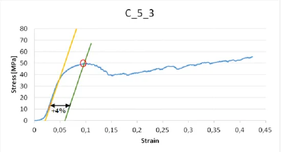
The offset yield strength was found by creating an offset line of 0.2% parallel to the interval of Young’s Modulus, and then perform an observation of the intersection with the stress-strain curve. In batch C there was a clear maximum point, while in batch A and B it was complicated to find the local maximum. Using batch C as reference, the permanent deformation corresponding to the maximum strength was determined. Its differnce to the offset line is 4% as shown by Figure 19. This value was then used for all the curves and futher called: offset compressive strength. The value for the offset compressive strength was found in the intersection point of the offset line and the stress-strain curve (Figure 19).
Figure 19. Determination of offset compressive strength.
Gibson & Ashby
There are methods that can be found in literature to model the physical and mechanical behaviour of open and closed cellular materials. One is Gibson & Ashby that analyses the model structures representative of the physical structure [46]. The model is developed from a stochastic open cellular foam, and have been extensively applied to metallic foams such as aluminium alloy, zinc alloy and magnesium alloy [37]. The model is based on a pentagonal dodecahedron and also later a model of Gibson & Ashby were hexagonal model of rod-like columnar structure. Nonetheless the cellular structure with the
hexagonal cross section were driven from bones where the loading is principally uniaxial for example the vertebral column. The method has typical expressions in form of equations and the approach is to determine the principal characteristics of the constitutive equation. This is done by experimentally determine the precise values of materials parameters for a given real material. One representative expression for
results [47] (Equation 7).
( ) Equation 7
Where E is Young’s Modulus measured from the specimens, Es is Young’s Modulus of full dense Ti-6Al-4V and n1 is a factor of 2. Voids reduce the fraction of load bearing section but could also be stress and strain concentrators throughout loading [47].
To more describe the materials behaviour Gibson & Ashby also proposed that the relative stiffness (E/Es) and relative density (ρ/ρs) and relative strength (σpl/σys) by the following expressions [48], [37]:
(ρ ρ ) Equation 8
ρ ρ (ρ ρ ) Equation 9
Where experimental evidences suggest that the factors n1=2, n2=1.5 should be used for open-cell foams and C1=1, C2=0.3 for cellular metals and polymers [48], [37].
3.4.4 Morphological analysis
The specimens, one from each structure and batch, were analysed by a stereomicroscope and a scanning electron microscope (SEM) to investigate
morphological information. This was performed according to the guidance document, excluding the parts that were only applicable for coatings. Following characteristics was investigated [49]:
1. The shape and size (average, standard deviation and range) of the material between the pores, i.e. the struts;
2. pore size (average and standard deviation) at the surface, both horizontal and lateral;
3. the minimum pore intercept length or minimum pore size of the interconnecting porosity (average, standard deviation and range); and
4. micrographs at appropriate magnifications and locations within the modified surface so all geometrical characteristics of the microstructure will be
recognizable should be done. If the original magnification is not used a micron bar should be included with each image.
In this thesis work it was the size of the voids on the surface that was measured. That means it was not possible to know if the measurement represented the largest diameter of the pore or just the beginning or end of it. In some cases it was therefore not the actual pore that was measured, according to the definition from some literature. Three different measurement was used to represent the void diameter: the minimum feret diameter (minFeret), the maximum feret diameter (maxFeret) and the equivalent diameter (Eq.Diameter). The feret diameter is the distance between two parallel
minimum and maximum distance that can be found with this approach (Figure 20). Since the minFeret seemed to fit the values of the designed pore size better the minFeret was decided to be referred to as the void size.
Figure 20. Visualization of feret diameter [49].
The morphological analysis was performed with a Nikon stereomicroscope in the Coatings and Industrial Corrosion Control Laboratory at DII at University of Trento. The surface, both the horizontal and lateral interface, of the specimens was analysed. The top surface was used to investigate the horizontal struts since the bottom surface had been cut in the manufacturing process. In batch A the specimens for the friction test were used and in batch B and C the specimens for the compression test were used. The analysis was made by the software NIS – Element. To measure the void size the edges of the voids was marked manually, atleast 3 for the regular structure and at least 10 for the irregular and fully random structure (Figure 21 and Figure 22). For the fully random structures and on the lateral surfaces it was hard to define the voids and therefore mark the edges of the voids, especially in the more dense structures. It was also difficult to measure the voids on the lateral side due to the curved surface (Figure 22). The software tool calculated the minFeret, maxFeret and the Eq.diameter and with these values the mean value, maximum value, minimum value and standard deviation were extracted. The measurements achieved were converted to Microsoft Excel.
Figure 21. Void size measurement of specimen A_5, horizontal side.
Figure 22. Void size measurement of specimen A_5, lateral side.
The shape and size of the struts, characteristics 1 was investigated by help of SEM (Figure 23). For every specimen atleast 3 to 5 measurements was made. Mean value, standard deviation, maximum value and minimum value was calculated. The same specimens that were used in the stereomicroscope were used in the SEM.
Figure 23. Strut size measurements of specimen A_9, horizontal surface.
3.4.5 Evaluation phase Ⅰ
To evaluate phase Ⅰ and continue to phase Ⅱ, a discussion took place with the project team of Eurocoating and the tutor of the thesis. The methods and results from phase Ⅰ (section 4.1) were presented and discussed together with aesthetic appearance. The result from the compression test was focused on the offset compressive strength, stiffness and the correlations between the structures and batches within these characterizations combined with porosity fraction. In the assessment of the
morphological information the emphasis was on real strut thickness and the void size. The result of phase Ⅰ was evaluated by the company and structures to perform the remaining test were selected.
The selected structures in phase Ⅱ were not designated because they were considered to be the most suitable, but to optimize the research information with as few specimens as possible since earlier result had shown that there were a lot of relations and trends to investigate. The chosen structures for the abrasion test were structures 1, 2 and 6 from batch C. The batch was chosen since it should be the least resistant to wear because of its high porosity and low compression strength. By testing structure 1, 2 and 6 all the different morphologies (regular, irregular and fully random) from the batch were tested. The tensile test was performed on structure 1, 2 and 6 in all three batches. Thus all the different types of morphologies were investigated.
3.5 Phase Ⅱ
Phase Ⅱ introduced a further investigation of a few selected structures with the remaining test methods: friction, tensile and abrasive.
3.5.1 Friction test
The friction properties were tested according to an internal standard; User’s manual of static friction provided by the University of Trento [51].
To determine the frictional characteristics of a material the coefficient of friction (COF) can be used. COF is the ratio of the force required to slide the surface to the force perpendicular to the surface. Static friction is the force that will resist motion to a
motion was precisely measured to determine the static COF. A software controls the test and plots a graphical representation of the static friction coefficient [50]. The specimens used are described in section 3.2.4.
Figure 24. Set up for the friction test.
To ensure that the result would not be affected by an edge effect the edges of the specimens were polished. The artificial bone of solid foam 1522-02 from Sawbone with a density of 0.24 g/cm3 replaced the flat table in the test. The artificial bone had to be cut in several pieces to fit the test setup. When performing the test the cut surfaces were not used since the surface finish were changed by the cut which could affect the result of the test. By the same reason each surface was never used more than once. The specimen and the applied load were weighted before they were placed on the surface with the sample holder and connected to the spring and force transducer. The equipment was controlled so it had a straight axis. The procedure was performed quickly and with approximately the same time for every specimen since the time would affect how attached the
specimen got to the bone. The force transducer was calibrated before each test. The parameters were configured into the software, NI myDAQ; motor velocity of 0.1 cm/s and the weight. 3 specimens from each structure and batch were tested.
3.5.2 Tensile test
Tensile test is a common way to determine the basic data of a material’s mechanical behaviour. The specimens are suitable designed to subject an increasing axial or uniaxial load until it fractures. With frequent intervals the load and elongation are measured and expressed as average stress and strain. The obtained data from the test is usually
extracted to stress-strain curves, (Figure 25), and can show the mechanical
characteristics of Young’s Modulus, ultimate tensile strength and yield strength. The ultimate tensile strength is the maximum load divided by the original area of the
the intersection point where the yield strength can be found, often 0.2% of offset strain to A’ [31].
Figure 25. Schematic drawing of a stress-strain curve from a tensile test [44].
To obtain the stress-strain curve the cross sectional area and the length of the trabecular structure were measured before the test. The specimens,section 3.2.5, were gripped in the testing machine by their threaded end section with 100 bar to make sure that the specimen did not slip during the test. All parameter settings were then configured into the softwareSerie ІΧ; constant crosshead speed of 1 mm/s and sampling rate of 1 kHz. The measurements were performed by the same machine as in the compression test in the Laboratory of Mechanical testing at DII at University of Trento. An extensometer, Instron dynamic extensometer 12.5 mm, was mounted on the surface in the edges of the trabecular structure in order to accurately record the displacement without including the artefacts from the machine (Figure 26).
Figure 26. Tensile test
For each specimens of same structure the same stress interval (20-70% of the yield strength) were selected to determine the Young’s Modulus in both the quasi static and cyclic test. The test was performed with the same software as in the cyclic compression test. Values for Young’s Modulus were obtained by using an Excel function to achieve the linear equation. The yield strength was defined by observing the curve since the 0.2% offset line did not show the yield point according to the shape of the curve. The ultimate tensile strength was found by searching for the maximum stress value in the stress-strain curve.
The test method propose a Taber Abraser model 5150 with H-22 Calibrade wheels, or equivalent, and no added weight to the abrading head. The specimen is abraded by turning it on a vertical axis against the sliding rotation of two abrading wheels.
Controlled conditions of pressure and abrasive action are of importance. One abrading wheel rubs the specimen outward and the other inward toward the centre which results in abrasion marks in form of a pattern of crossed arcs. The test will be performed
repeated times for a cumulative amount of cycles (2, 5, 10, and 100) [42].
Before every cycle the specimens should be cleaned for 10 minutes with an ultrasonic cleaner. The specimens should then dry for 10 minutes in an oven, 100°C. After each cleaning the specimens are weighted. In short, the procedure steps were:
1. Cleaning with an ultrasonic cleaner for ten minutes. Drying in a 100°C oven for ten minutes.
Weighting =start weight 2. Test 2 cycles
Cleaning, drying and weighting 3. Test 3 cycles = total 5 cycles
Cleaning, drying and weighting 4. Test 5 cycles = total 10 cycles
Cleaning, drying and weighting 5. Test 90 cycles = total 100 cycles
Cleaning, drying and weighting
The measure of the abrasive wear is calculated from the mass loss of the specimen with Equation 11 [42]:
Equation 11
Where n is number of cumulative cycles to which specimen has been exposed (2, 5, 10 or 100), Δwn is cumulative mass loss for n cycles, <w0> is average mass at the start of the test and <wn> is average mass after n cumulative cycles [42].
According to the industry guidance document the weight loss should be less than a total of 65 mg by weight after 100 cycles [49].
The tests were performed in the Materials Characterization Laboratory at DII at University of Trento ( Figure 27). The specimens used are described in section 3.2.6. Since there was a metallic structure and not a coating that was tested the standard procedure was deviated. This since the weight loss was predicted to be much lower than the accepted weight loss. The test was made as an investigation and not to validate the substrate, so a deviation from the standard was considered to be acceptable. To make the test procedure faster and simpler step 4, testing 5 cycles to reach a total of 10 cycles, was skipped. That resulted in a total of 95 cycles. Step 2 and 3 was decided to both be
performed to see if there were some interesting occurrences in the first cycles of the test.
Figure 27. Taber Abraser machine with Taber specimen.
Since abrasive wear is defined by the indentation of a hard body into a softer body. A high hardness of the base material is therefore a good protection against abrasive wear [52]. The mass loss was therefore compared with the offset compressive strength.
![Figure 5. Microstructure of Ti-6Al-4V with 3 different magnitudes [27].](https://thumb-eu.123doks.com/thumbv2/5dokorg/5404265.138479/15.892.156.741.105.584/figure-microstructure-ti-al-v-different-magnitudes.webp)