upppEena
sn
Nr 320 A« 1982 A tas Statensvag- och trafikinstitut (VTI) * 581 01 Linképi ng fISSN 0347-6049 : National Road & Traffic Research Institute * S-581 01 Linkoping ® Sweden
Equipmentforfrost heavetests
a Friction between Plas
tic and Soil
ENEE'
Nr 320 A 0 1982 Statens vétg- och trafikinstitut (VTI) ' 581 01 Linkb ping ISSN 0347~6049 National Road 8: Traffic Research Institute 0 S-581 01 Linképing - Sweden
Equipment for frost heave tests
Friction between Plastic and Soil
STATENS VXG- OCH TRAFIKINSTITUT
Végavdelningen 1982-11-01 1:e fo ing L Stenberg/eh
Equipment for frost heave tests Friction between plastic and soil Friktion mellan akryiplast och moran
Vid VTI har framtagits en apparatur for tjallyftnings studier. Dessa utfores sa att jordarten packas 1 en plastcylinder och belastas under ett dygn, varefter frysning sker underifran. Genom detta forfaringssatt forskjutes den ofrusna delen av provet uppat. Den
har-igenom uppkomna friktionskraften kommer att ha samma inverkan pa tjallyftningen som en okad belastning. Den
har redovisade studien avsag att studera
forbelast-ningens inverkan pa friktionen mellan cylindervagg och jordart. Resultaten pekar pa att friktionens hammande
inverkan pa tjallyftningen med avsikt pa belastning
maximalt ar av samma storleksordning som ett barlager med overlagrande belaggningsmassa. Friktionen kan alltsa bedomas ha liten betydelse for tjallyftningen i undergrundsmaterial, vilka studeras genom frysning med VTI:s apparatur for tjallyftningsstudier.
TABLE OF CONTENTS
Page
Introduction 1
Determining the friction between plastic and soil 1
Procedure 1
Conclusions 6
Introduction
At the National Swedish Road and Traffic Research Institute, an apparatus has been develOped for the determination of the frost heaving prOperties of
different soils (Stenberg, L 1981). The test soils are frozen from below, confined in a plastic cylinder. During freezing, the unfrozen soil material is pushed upward by the frost heaving force, thus sliding against the cylinder wall. This movement causes a counteracting friction force which will have the same influence on the frost heave as an increased load pressure. It has been argued that the magnitude of this counterforce is of great concern. A test has been performed as de
scribed to determine the friction against the plastic cylinder.
Determining the friction between plastic and soil
The test was divided into four groups where the content
of water in the mixture varied, viz: a) 50 grs, b)
100 grs, c) 150 grs and d) 200 grs for 1700 grs of dry soil, a till with a maximum grain size diameter of 200 mm.
Each of this major group was then subdivided where the weight applied on to the mixture varied, i.e. a) 10 kg, b) 20 kg and c) 30 kg. However, each of these groups and subgroups were made in an identical procedure.
Procedure
Into four bowls containing 1700 grs of dry soil each, the right amount of water is added and mixed thoroughly. The content of each bowl is then transferred into an acrylic plastic cylinder each.
The plastic cylinder is open at both ends. A bronze gauze, whose diameter is slightly less than the inside diameter of the cylinder, is inserted into the bottom-end of the cylinder. The gauze is then covered with a
filter paper of equal radius to prevent fine soil
particles from creeping through the gauze.
The soil-water is then transferred in small quantities at a time and stamped lightly into place in the
cylinder. When all the content of the bowl is thus transferred, the appropiate weight is placed on top of the mixture very carefully. After a lapse of 6 to
8 hours, the height of the soil in the cylinder is
measured and noted. All the weight that is on the
mixture is removed leaving only a weight of 5 kg. The cylinder is placed on a cylinder shaped pedestal,
"B", figure 1. Since "B"'s radius is less than the
radius of the inside of the cylinder, this arrangement
leaves the cylinder wall hanging in the air. Therefore, One has to be more careful when one places the ring-frame, "A", onto the cylinder. This done, the next step is to set on the pressurizer.
When the pressurizer is on the piston, its downward motion transmits a force onto "A", which forces the
cylinder to slide down. The content of the cylinder remains stationary supported by "B".
The force thus applied is registered on a graphic paper as a function of time. The results are compiled
n
d
r
lf
er
pup
er
Pi
st
on
"8
"-Cyl
in
de
r
sh
ap
ed
pe
de
st
al
"A
"-Ri
ng
fr
dm
e
Cy
F
/
Br
on
ze
gd
uze
,0 v.v.vv.v O.v.v.o $555UN%VVV0 90000004 .9 oooooooql. w
g gq
a ooo %od§o""1mu
1!
m
!l. . 7 " W M L...T e s t d e s i g n a n d e q ui p m e n t 1. F i g ur e
A
x 10 KG PRELOAD
o 20
~-a 30
--~
o10,0
CL A!E
a 8,0«
U) UJ CZ CL E 6,0 x act * Z 3 X X C) U X X2 4,0
m
O x O E. A xo 0 o o - A E 2,0 8 0 m A 4%0 AAct) o o A A2
A
6
8
10
12
WATER CONTENT °/o DRY WEIGHT
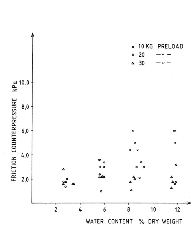
Figure 2. Diagram showing registered friction force per
envelope surface at various water content and pre-loading.
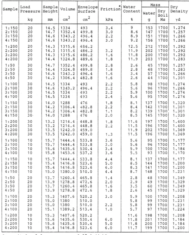
Table 1. Test results with till (salen)
r Mass
Load Sample Envelope . . * Water Dry sample Pressure Height VOlume Surface FrlCtlon Content Water Dry Density
Soil kg mm cm3 cm2 kPa % g Ms yd 1:150 20 14.5 1334 493 3,4 9 153 1700 1.274 2:150 20 14.7 1352.4 499.8 3.0 8.6 147 1700 1.257 3:150 20 14.6 1343.2 496.4 2.2 8.9 151 1700 1.266 4:150 20 14.6 1343.2 496.4 3.0 9.2 156 1700 1.266 1:200 20 14.3 1315.6 486.2 12.5 212 1700 1.292 2:200 20 14.3 1315.6 486.2 3.2 11.9 202 1700 1.292 3:200 20 14.3 1315.6 486.2 1.6 11.8 200 1700 1.292 4:200 20 14.4 1324.8 489.6 1.8 11.9 203 1700 1.283 1:50 30 14.7 1352.4 499.8 2.8 2.6 45 1700 1.257 2:50 30 14.4 1324.8 489.8 1.8 2.8 48 1700 1.283 3:50 30 14.6 1343.2 496.4 1.6 3.4 57 1700 1.266 4:50 30 14.2 1306.4 482.8 1.6 2.6 44 1700 1.301 1:100 30 14.5 1334 493 2.2 5.8 98 1700 1.274 2:100 30 14.6 1343.2 496.4 2.2 5.6 96 1700 1.266 3:100 30 14.5 1334 493 2.2 5.9 100 1700 1.274 4:100 30 14.5 1334 493 2.4 5.6 95 1700 1.274 1:150 30 14.0 1288 476 1.8 8.1 137 1700 1.320 2:150 30 14.2 1306.4 482.8 2.2 8.4 142 1700 1.301 3:150 30 14.2 1306.4 482.8 1.1 8.2 139 1700 1.301 4:150 30- 14.0 1288 476 2.0 8.5- 145 1700 1.320 1:200 30 13.2 1214.4 448.8 1.8 11.6 197 1700 1.400 2:200 30 13.2 1214.4 448.8 2.2 11.5 196 1700 1.400 3:200 30 13.5 1242.0 459.0 11.9 202 1700 1.369 4:200 30 13.5 1242.0 459.0 1.3 11.5 196 1700 1.369 1:100 10 15.7 1444.4 533.8 3.6 5.6 95 1700 1.177 2:100 10 15.7 1444.4 533.8 3.0 5.6 96 1700 1.177 3:100 10 15.6 1435.6 530.4 3.4 5.9 100 1700 1.184 4:100 10 15.8 1453.6 537.2 3.6 5.5 93 1700 1.170 1:150 10 15.7 1444.4 533.8 4.4 8.1 137 1700 1.177 2:150 10 15.4 1416.8 523.6 5.0 8.5 144 1700 1.200 3:150 10 15.4 1416.8 523.6 6.0 8.3 141 1700 1.200 4:150 10 15.0 1380.0 510.0 4.4 8.7 148 1700 1.231 1:50 20 13.7 1260.4 465.8 1.4 2.8 48 1700 1.349 2:50 20 13.9 1278.8 472.6 2.0 2.9 49 1700 1.329 3:50 20 13.7 1260.4 465.8 1.6 3.5 60 1700 1.349 4:50 20 13.9 1278.8 472.6 1.8 2.6 45 1700 1.329 1:100 20 15.3 1407.6 520.2 3.0 5.9 100 1700 1.208 2:100 20 15.0 1380 510.0 5.8 99 1700 1.231 3:100 20 15.0 1380 510.0 2.2 5.8 99 1700 1.231 4:100 20 15.1 1389.2 513.4 1.0 5.7 97 1700 1.224 1:200 10 15.3 1407.6 520.2 11.6 198 1700 1.208 2:200 10 15.6 1435.6 530.4 6.0 11.8 201 1700 1.184 3:200 10 15.6 1435.6 530.4 5.0 11.8 200 1700 1.184 4:200 10 15.4 1416.8 523.6 6.0 11.7 199 1700 1.200 * magnitude of frame pressure 0.37-0.41 kPa
Conclusions
The measured friction forces cause a pressure against the frost heaving of a magnitude comparable to load pressure exerted by a thin pavement. When studying the frost heaving of subsoils, this pressure is negligible. For samples pre-loaded with 10 kg there is an increase in friction with water content. This effect is probably due to the test performance. The lesser the pre-load is,
the higher the freedom of the particles to move will be,
and thus causing friction against the wall, and also to
get in between the pedestal and cylinder, causing
fric-tion between the two. With a higher pre-loading, 30 kg, the soil mass will be more compressed and will shrink by its elasticity as the load pressure is removed, thus giving rise to a lesser friction against the cylinder wall.
References
Stenberg, L. 1981. Frost Heave Tests with Constant Rate of Heat Extraction. VTI Rapport 220 A, ISSN 0347 6030.