Models for analysis of young cast
and sprayed concrete subjected
to impact-type loads
LAMIS AHMED
Doctoral Thesis
Stockholm, Sweden 2015
TRITA-BKN. Bulletin 132, 2015 ISSN 1103-4270 ISRN KTH/BKN/B--132--SE KTH School of ABE SE-10044 Stockholm SWEDEN Akademisk avhandling som med tillstånd av Kungliga Tekniska högskolan framlägges till offentlig gransking för avläggande av teknologie doktorsexamen i Byggvetenskap, med inriktning mot Betongbyggnad, tisdagen den 9 juni 2015, klockan 10:00 i sal D2, Lindstedtsvägen 5, Stockholm.
i
Abstract
The strive for a time-efficient construction process naturally put focus on the possibility of reducing the time of waiting between stages of construction, thereby minimizing the construction cost. If recently placed concrete, cast or sprayed, is exposed to impact vibrations at an early age while still in the process of hardening, damage that threatens the function of the hard concrete may occur. A waiting time when the concrete remains undisturbed, or a safe distance to the vibration source, is therefore needed. However, there is little, or no, fully proven knowledge of the length of this distance or time and there are no established guidelines for practical use. Therefore, conservative vibration limits are used for young and hardening concrete exposed to vibrations from e.g. blasting.
As a first step in the dynamic analysis of a structure, the dynamic loads should always be identified and characterized. Here it is concluded that impact-type loads are the most dangerous of possible dynamic loads on young and hardening concrete. Shotcrete (sprayed concrete) on hard rock exposed to blasting and cast laboratory specimens subjected to direct mechanical impact loads have been investigated using finite element models based on the same analysis principles. Stress wave propagation is described in the same way whether it is through hard rock towards a shotcrete lining or through an element of young concrete. However, the failure modes differ for the two cases where shotcrete usually is damaged through loss of bond, partly or over larger sections that may result in shotcrete downfall. Cracking in shotcrete due to vibrations only is unusual and has not been observed during previous in situ tests. The study of shotcrete is included to demonstrate the need of specialized guidelines for cases other than for mass concrete, i.e. structural elements or concrete volumes with large dimensions in all directions.
Within this project, work on evaluating and proposing analytical models are made in several steps, first with a focus on describing the behaviour of shotcrete on hard rock. It is demonstrated that wave propagation through rock towards shotcrete can be described using two-dimensional elastic finite element models in a dynamic analysis. The models must include the material properties of the rock and the accuracy of these parameters will greatly affect the results. It is possible to follow the propagation of stress waves through the rock mass, from the centre of blasting to the reflection at the shotcrete-rock interface. It is acceptable to use elastic material formulations until the strains are outside the elastic range, which thus indicates imminent material failure. The higher complexity of this type of model, compared with mechanical models using mass and spring elements, makes it possible to analyse more sophisticated geometries. Comparisons are made between numerical results and measurements from experiments in mining tunnels with ejected rock mass and shotcrete bond failure, and with measurements made during blasting for tunnel construction where rock and shotcrete remained intact. The calculated results are in good correspondence with the in situ observations and measurements, and with previous numerical modelling results. Examples of preliminary recommendations for practical use are given and it is demonstrated how the
ii
developed models and suggested analytical technique can be used for further detailed investigations.
The modelling concept has also been used for analysis of impact loaded beams and concrete prisms modelled with 3D solid elements. As a first analysis step, an elastic material model was used to validate laboratory experiments with hammer-loaded concrete beams. The laboratory beam remained un-cracked during the experiments, and thus it was possible to achieve a good agreement using a linear elastic material model for fully hardened concrete. The model was further developed to enable modelling of cracked specimens. For verification of the numerical results, earlier laboratory experiments with hammer impacted smaller prisms of young concrete were chosen. A comparison between results showed that the laboratory tests can be reproduced numerically and those free vibration modes and natural frequencies of the test prisms contributed to the strain concentrations that gave cracking at high loads. Furthermore, it was investigated how a test prism modified with notches at the middle section would behave during laboratory testing. Calculated results showed that all cracking would be concentrated to one crack with a width equal to the sum of the multiple cracks that develop in un-notched prisms. In laboratory testing, the modified prism will provide a more reliable indication of when the critical load level is reached.
This project has been interdisciplinary, combining structural dynamics, finite element modelling, concrete material technology, construction technology and rock support technology. It is a continuation from previous investigations of the effect on young shotcrete from blasting vibrations but this perspective has been widened to also include young, cast concrete. The outcome is a recommendation for how dynamic analysis of young concrete, cast and sprayed, can be carried out with an accurate description of the effect from impact-type loads. The type of numerical models presented and evaluated will provide an important tool for the work towards guidelines for practical use in civil engineering and concrete construction work. Some recommendations on safe distances and concrete ages are given, for newly cast concrete elements or mass concrete and for newly sprayed shotcrete on hard rock.
Keywords: Young concrete · Shotcrete · Rock · Impact-type vibration · Finite element method · Fracture mechanics model · Crack width
iii
Sammanfattning
Strävan efter en tidseffektiv byggprocess fokuserar på ett naturligt sätt på möjligheten att minska väntetidetider mellan byggetapper, vilket minimerar byggkostnaden. Om nyligen placerad betong, gjuten eller sprutad, utsätts för vibrationer av stöttyp vid tidig ålder då härdningsprocessen fortfarande pågår, finns risk för skador som hotar att försämra funktionen hos den fullhårdnade betongen. Därför behövs en väntetid där betongen förblir ostörd, eller ett säkert avstånd till vibrationskällan. Det finns däremot liten eller ingen fullt vedertagen kunskap om längden på detta avstånd, eller tidsperiod, och det finns heller inga fastställda riktlinjer för praktisk användning. Därför används idag konservativa gränsvärden för ung och hårdnande betong som utsätts för vibrationer från t.ex. sprängning.
Som ett första steg i en dynamisk analys av en struktur ska de dynamiska lasterna alltid identifieras och karakteriseras. För de typer av dynamiska belastningar som kan verka på ung och hårdnande betong är effekten från laster av stöttyp den allvarligaste. De två fallen med sprutbetong på hårt berg utsatt för sprängning och gjutna laboratorieprovkroppar utsatta för direkt mekanisk stötlast har undersökts med hjälp av finita elementmodeller baserade på samma analysprinciper. Spänningsvågornas utbredning beskrivs på samma sätt oavsett om det är genom hårt berg mot en sprutbetongyta eller genom ett konstruktionselement av ung betong. Dock är brottmoderna olika för de två fallen, där sprutbetong oftast skadas genom vidhäftningsbrott, delvis eller över större sektioner vilket kan leda till nedfall av sprutbetong. Sprickbildning i sprutbetong på grund av enbart vibrationer är ovanligt och har inte observerats under tidigare fältförsök. Studien av sprutbetong har medtagits för att påvisa behovet av specialiserade riktlinjer för andra fall än för massiva betongkonstruktioner, dvs. strukturella element eller betongvolymer med stora dimensioner i alla riktningar.
Inom detta projekt genomförs arbetet med att utvärdera och föreslå analysmodeller i flera steg, först med fokus på att beskriva beteendet hos sprutbetong på hårt berg. Det visas att vågutbredning genom berget mot sprutbetongen kan beskrivas med hjälp av tvådimensionella elastiska finita elementmodeller i en dynamisk analys. Modellerna måste inkludera bergmaterialets egenskaper och riktigheten hos dessa parametrar kommer att ha stor påverkan på resultaten. Det är möjligt att följa utbredningen av spänningsvågor genom bergmassan, från sprängningens centrum till reflektion vid gränsskiktet mellan sprutbetong och berg. Tillräcklig noggrannhet ges med elastiska materialformuleringar, tills töjningar överskrider det elastiska området vilket indikerar förestående materialbrott. Den högre komplexiteten hos denna typ av modell, jämfört med mekaniska modeller med massor och fjäderelement, kommer att möjliggöra analyser med avancerade geometrier. Jämförelser görs här mellan numeriska resultat och mätningar från experiment i gruvtunnlar, med utstött bergmassa och vidhäftningsbrott, och med mätningar gjorda under sprängning för tunnelbygge, där berg och sprutbetong förblev intakta. De beräknade resultaten är i god överensstämmelse med fältförsöken och med tidigare presenterade numeriska resultat. Exempel på preliminära
iv
rekommendationer för praktiskt bruk ges och det visas hur föreslagen analysteknik och de utvecklade modellerna kan användas för kommande detaljerade undersökningar.
Modelleringskonceptet har också använts för analys av stötbelastade balkar och betongprismor som har modellerats med solida 3D element. I en första analys användes en elastisk materialmodell för att validera ett laboratorieexperiment med hammarbelastade betongbalkar. Laboratoriebalken förblev oförstörd under provningen och därmed var det möjligt att uppnå god överensstämmelse med en linjärelastisk materialmodell för fullt hårdnad betong. Modellen utvecklades ytterligare för att möjliggöra modellering av spruckna provkroppar. För kontroll av de numeriska resultaten valdes en tidigare genomförd serie laboratorieförsök med hammarbelastade mindre prismor av ung betong. En jämförelse mellan resultaten visade att laboratorieresultaten kan återges numeriskt och att provkropparnas fria vibrationsmoder och egenfrekvenser bidragit till spänningskoncentrationer som gav sprickbildning vid höga belastningar. Dessutom har det undersökts hur en sådan provkropp, modifierad med skåror i mittsektionen, skulle bete sig under samma laboratorieförsök. Beräkningsresultat visade att all sprickbildning då skulle koncentreras till en spricka med en bredd som är lika med summan av de flera sprickor som utvecklas i en oskårad provkropp. I laboratorietester kommer den modifierade provkroppen att ge en mer tillförlitlig indikation på när den kritiska skade- och belastningsnivån nås.
Projektet har varit tvärvetenskapligt och kombinerat strukturdynamik, finit elementmodellering, betongmaterialteknik, konstruktionsteknik och bergförstärkningsteknik. Det är en fortsättning från tidigare undersökningar av effekten på ung sprutbetong från sprängningsvibrationer, men detta perspektiv har vidgats till att även omfatta ung gjuten betong. Resultatet består av rekommendationer för hur dynamisk analys av ung betong, gjuten och sprutad, kan genomföras med en korrekt beskrivning av effekten från laster av stöttyp. Den typ av numeriska modeller som presenterats och utvärderats kommer att vara ett viktigt verktyg för arbetet med att ta fram riktlinjer för praktisk användning vid anläggnings- och betongbyggnadsarbete. Några rekommendationer för säkerhetsavstånd och minimiåldrar ges, för nygjutna betongelement eller massiva betongkonstruktioner och för nyligen applicerad sprutbetong på hårt berg.
Nyckelord: Ung betong · Sprutbetong · Berg · Stötar och vibrationer · Finita elementmetoden · Brottmekaniksk modell · Sprickbredd
v
Preface
The work has been carried out at the KTH Royal Institute of Technology, Division of Concrete Structures. The study was made possible through financial support from BeFo, Rock Engineering Research Foundation and SBUF, the Development Fund of the Swedish Construction Industry. Support to the first part of the Project also came from Formas, The Swedish Research Council for Environment, Agricultural Science and Spatial Planning. The support is gratefully acknowledged.
I would like to express my sincere thanks and gratitude to my supervisor Professor Anders Ansell and assistant supervisor Ph.D. Richard Malm for their guidance, assistance, supervision, and encouragement during the term of this project.
I also wish to express my grateful thanks to the staff of the laboratory at Department of Civil and Architectural Engineering at KTH for providing all the necessities for executing the laboratory works.
Appreciation thanks to Professor Jonas Holmgren for his support, to all my colleagues and especially thanks to my brother Ahmad and his family.
Stockholm, June 2015
vii
List of appended papers
The thesis contains the following research papers, referred to in the text by their roman numerals:
I. Ansell A, Ahmed L. Impact load vibrations on young concrete. Submitted to Structural Concrete, 2015.
II. Ahmed L, Ansell A. Laboratory investigation of stress waves in young shotcrete on rock. Magazine of Concrete Research 64(10):899-908, 2012.
III. Ahmed L, Ansell A. Structural dynamic and stress wave models for the analysis of shotcrete on rock exposed to blasting. Engineering structures 35:11-17, 2012.
IV. Ahmed L, Ansell A, Malm R. Finite element simulation of shotcrete exposed to underground explosions. Nordic Concrete Research 45:59-74, 2012.
V. Ahmed L, Ansell A. Vibration vulnerability of shotcrete on tunnel walls during construction blasting. Tunnelling and Underground Space Technology 42:105–111, 2014.
VI. Ahmed L, Ansell A, Malm R. Numerical modelling and evaluation of laboratory tests with impact loaded young concrete prisms. Submitted to Materials and Structures, 2015.
Paper I was mainly written by Ansell, with Ahmed contributing to the literature search and evaluation of the results. For Papers II, III and V, Ahmed carried out the laboratory investigation, performed the numerical calculations and wrote the paper together with Ansell. The numerical calculations in Paper IV and VI were done by Ahmed with contributions from Malm. The evaluation of the results and writing of the paper was done by Ahmed together Ansell and Malm.
viii
As complement to the above papers, the following additional reports and conference papers have been published during the project:
Ahmed L. Models for analysis of shotcrete on rock exposed to blasting. Licentiate thesis. Stockholm: KTH Royal Institute of Technology; 2012.
Ahmed L. Laboratory simulation of blasting induced bond failure between rock and shotcrete. Stockholm: Rock Engineering Research Foundation. BeFo report 116, 2012.
Ahmed L, Ansell A. Behaviour of sprayed concrete on hard rock exposed to vibration from blasting operations. Proceeding of 7th International Conference on
Sprayed Concrete. Sandefjord: The Norwegian Society of Graduate Technical and Scientific Professionals, Tekna; 2014.
Ahmed L, Ansell A. Experimental and numerical investigation of stress wave propagation in shotcrete. In: XXI Symposium on Nordic Concrete Research and Development. Hämeenlinna: Nordic Concrete Research; 2011.
Ahmed L, Ansell A. A comparison of models for shotcrete in dynamically loaded rock tunnels. Proceedings of the 3rd international conference on engineering developments in shotcrete. Queenstown: Australian Shotcrete Society and the American Shotcrete Association; 2010.
ix
Contents
Abstract ... i
Sammanfattning ... iii
Preface ... v
List of appended papers ... vii
1 Introduction ... 1
1.1 Background ... 1
1.2 Early age concrete ... 2
1.3 Shotcrete ... 4
1.4 Aims and goals ... 5
1.5 Outline of thesis ... 6
2 Impact-type vibrations ... 9
2.1 Dynamic load types ... 9
2.2 Traffic vibrations ... 12
2.3 Machine vibrations and pile-driving ... 13
2.4 Blasting ... 14
3 Impact vibration limits and guidelines ... 15
3.1 Standards and specifications ... 15
3.2 Young concrete vibration limits ... 16
3.3 Shotcrete vibration limits ... 18
4 In situ and laboratory investigations ... 21
4.1 Laboratory testing ... 21
4.1.1 Bond failure ... 21
4.1.2 Poisson’s ratio ... 24
4.2 Summary of earlier laboratory tests ... 26
x
4.4 Tunnelling blasting measurements ... 28
5 Dynamic analysis ... 31
5.1 Structural dynamic models ... 31
5.2 Finite element models ... 34
5.2.1 Wave propagation in prototype rock ... 34
5.2.2 Tunnelling blast vibrations ... 35
5.2.3 In situ case study ... 42
5.2.4 Mass concrete subjected to impact ... 43
6 Summary of appended papers ... 49
7 Recommendations ... 53
7.1 Finite element modelling ... 53
7.2 Practical guidelines ... 53
7.3 Further research ... 54
8 Discussions and conclusions ... 55
8.1 Load type ... 55
8.2 Test results and measurement ... 56
8.3 Numerical modelling techniques ... 56
8.4 Concrete and shotcrete ... 57
1
Introduction
A criterion for how severe impact induced vibrations that can be allowed to reach young and hardening concrete is needed for efficient civil engineering projects, e.g. casting of concrete foundations on ground, tunnelling or other underground constructions. Striving for a more time-efficient construction process naturally focuses on the possibilities of reducing the times of waiting between stages of construction, which will lead to a reduced construction cost.
1.1 Background
Recently placed, young and hardening concrete is vulnerable to high intensity vibrations of impact-type that may cause a reduction of its strength in the hardened state. Vibration stress waves will propagate through a concrete volume and depending on the existence of free and restrained boundary surfaces, compressive and tensile stresses will appear. Since the compressive strength of concrete is higher than the tensile strength, damage due to tensile cracking of the concrete matrix may occur during the hardening process. The damaging mechanisms inside curing concrete subjected to impact-type vibrations are complicated and little is known about their effects. Therefore, conservative vibration limits have been used for hardening concrete exposed to vibrations, in many cases leaving engineers to conduct empirical investigations and testing without any clear and reliable guidelines given. This is reflected in the differences that exist between limits specified in different national standards and handbooks, often given with allowed peak particle velocity (PPV) at a certain point where damage protection is required.
The allowable PPV levels vary strongly as the concrete hardens and its strength increases. Also, the maximum PPV that can be allowed close to recently placed concrete depends on geometry, construction type, and load situation and may be fundamentally different if e.g. mass concrete or shotcrete (sprayed concrete) is studied. The damage caused in shotcrete on rock is often the result of bond failure while damage on aboveground concrete structures from e.g. underground blasting is due to structural dynamic response problems. Therefore, it is necessary to determine reliable safety limits for impact vibration in relation to concrete type, concrete ages, dynamic characteristics, etc. However, to establish reliable guidelines comparison between in situ or laboratory observations and measurements with finite element modelling results are needed to gain the understanding of the causes of possible damage in young concrete exposed to severe vibrations.
CHAPTER 1.INTRODUCTION
2
This project is a continuation from previous investigations of the effect on young shotcrete from blasting vibrations. In situ tests were conducted underground in a Swedish mine [9], as a first step towards reliable guidelines for how close, in time and distance, to young and hardening shotcrete blasting can be allowed. The in situ tests were evaluated using comparisons with results from numerical models [8, 10-11]. These were based on elastic stress wave theory and structural dynamics and with relatively small computational effort made it possible to compare a large number of calculations with various combinations of input data. The first phase of this project has also been presented in a licentiate thesis [2] and its appended papers, here also included as Papers II, III and IV, on models for analysis of shotcrete on rock exposed to blasting. The previously used engineering models were compared and evaluated through calculations and comparisons with existing data. Results from a non-destructive laboratory experiment were also used to provide test data for the models. A more sophisticated, dynamic finite element model was also developed and tested using the numerical program Abaqus [119]. This allows modelling of more complex geometries and provides more detailed analysis results. The second phase, presented here together with the conclusion from the first part of the project, also studies the effect from vibrations on young and hardening cast concrete. The developed and tested finite element model is here also used with a non-linear material formulation that can simulate concrete cracking. The case with shotcrete on hard rock is thus a special case that can be analysed with similar methods as cast concrete elements and volumes, but for other geometries and material properties. The most important difference is here the failure modes, where cast concrete develops cracks while shotcrete often fails due to loss of bond to the rock.
1.2 Early age concrete
There are several alternative definitions of ‘early age concrete’, used differently within the various fields of concrete engineering and research. A review of common terms and their corresponding time spans is presented by Ansell and Silfwerbrand [4], here summarized in Table 1.1. The term ‘young concrete’ often refers to recently placed concrete, being 0 – 12 hours old while ‘old concrete’ is concrete older than one week. For ages between young and old, the term ‘intermediate age concrete’ is used. With reference to the hardening process, ‘initial setting’ corresponds to the time when concrete is no longer workable and has very little or no slump while ‘final setting’ indicates the time at which the concrete begins to harden, but when still no measurable strength can be observed, [98].The American Concrete Institute [1] defines ‘early age of concrete’ as the period after final setting during which properties are changing rapidly. This definition is similar to that for ‘green concrete’, defined as concrete that has undergone final setting but not fully hardened. These two definitions imply that the concrete has reached final set but has not gained much strength. The early strength of concrete or mortar is usually [1] given at various times during the first 72 hours after placement, for ‘early age concrete’ often defined as concrete between setting and approximately 24–72 hours old, [29]. Research findings indicate that the setting period represents the interval of the most rapid hydration, followed by a period of reduced hydration activity, i.e. induction. The beginning of the setting period is not mainly defined since it depends on many factors, i.e. type of cement, water/cement ratio, temperature, etc. However, e.g. the Swedish Concrete handbook [128] states that the setting period starts after 3–5 hours from the first contact between water and cement. Through the setting period, a major portion of the cement hydrates and then solidifies which normally continues up to 24–72 hours. In the present study, ‘early age concrete’ is used to denote concrete less than 72 hours old. For very
1.2EARLY AGE CONCRETE
3
early ages the term ‘young concrete’ is used, which here represents the period from first contact between cement and water up to 12 hours of age. The most critical concrete age is often assumed to be within 3–14 hours after casting, but is believed to vary with the type of concrete and curing conditions, see [4 and 64]. Concrete ages are often also defined with respect to equivalent time, which depends on temperature and thus the rate of hardening. The measure is then often the compressive strength and workability of the hardening concrete. An example is given by Fjellström et al. [42] who define ‘fresh concrete’ as concrete that can be placed and vibrated without damage to the cement structure, i.e. similar to the definition by Byfors [29] in Table 1.1. The following time period is referred to as a ‘surface finishing
period’ which is the time between initial and final setting when final work can be made to the
concrete surface. The third period is the ‘hardening period’ that typically begins from a compressive strength of around 0.5 MPa. However, it should be remembered that apart from curing and placing temperatures, concrete material properties such as damping characteristics, use of admixtures, types and number of binders, i.e. cement and fly ash [133], are also important for when young concrete is as most sensitive to vibration damage.
Table 1.1: A compilation of terminology for young and early age concrete, from [4].
Term Concrete ages Definition given by:
Fresh concrete concrete before setting Byfors [29]
Green concrete freshly placed, 24 hours Hulshizer and Desai [63]
Young concrete 0–12 hours Akins and Dixon [3]
Early age concrete between setting and app. 1–3 days Byfors [29]
Intermediate age concrete 12 hours – 7 days Akins and Dixon [3] Almost hardened concrete app. 1–3 days to 28 days Byfors [29]
Old concrete 7 days Akins and Dixon [3]
Hardened concrete 28 days Byfors [29]
There are often practical problems associated with testing of young and hardening concrete. Material properties such as compressive strength, tensile strength and modulus of elasticity are difficult to measure on concrete younger than 12 hours. For younger concrete it may be difficult to remove casting moulds for stiffness or strength measurement, [73]. Despite this, the effects of vibration on early age concrete have been studied through a number of tests carried out using widely different methods. A variety of methods for applying vibration loads to concrete test specimens has been used. These vary from hammering the specimens to produce impact vibration, or vibrating the specimens on a shaker table, to subjecting the specimens to ground vibrations at a construction site. The latter is often done by placing concrete specimens adjacent to sources of construction-induced vibration such as rock-blasting, pile-driving, heavy traffic, or machine vibrations, as further explained in [Paper I]. There is no agreement on how vibration damage to the concrete should be defined and detected. Measurement of only the compressive strength of vibration-exposed and later hardened concrete specimens might not reveal the full effects of the shock vibration applied [75]. There might also be difficulties in detecting damage from vibrations in early age concrete since e.g. hairline cracks are difficult to observe with the naked eye. However, early
CHAPTER 1.INTRODUCTION
4
investigations such as the study by Esteves [41], relied on visual inspection to detect surface cracks as a sign of vibration damage to the concrete, [36 and 61]. Due to this, large variations in the results between experimental studies can be seen demonstrating that more clear failure criteria such as reduction in compressive or tensile strength should be used. The vibration resistance of concrete depends more on tensile than on compressive strength, and vibration damages also show mainly in the form of cracking and reduction in tensile strength, [73]. However, because tensile strength is more difficult to test than compressive strength, especially for young concrete, many researchers therefore omitted to investigate the tensile strength. One reason is that reinforced concrete is often designed in the cracked state making tensile strength less important with respect to impact vibrations in such cases, see e.g. Hulshizer and Desai [63]. Thus, due to the lack of detailed knowledge of how vibrations cause damage to early age concrete there are no generally accepted methods for estimating these limits. In some tests, despite shock vibrations up to what was believed to be a very high PPV, no damage to the concrete specimens had been detected. In most of these tests, the threshold vibration intensity that would cause vibration damage had not yet been reached and the results obtained were only safe PPV levels that would not cause vibration damage, and no ultimate vibration limits. Although the tensile strength is relatively low during the first 24 hours after casting, it has been suggested that within the first 2 hours, i.e. before initial set, young concrete is able to withstand PPV up to 100 mm/s, [63 and 104], and may also benefit from the re-vibration [4].
1.3 Shotcrete
Shotcrete is concrete projected pneumatically onto a surface, using either the dry mix or the wet mix method. The latter has been widely used for tunnelling work in hard rock and its flexibility in the choice of application thickness, material compositions (e.g., fibre content), output capacity and fast early strength development makes shotcrete a material well suited for rock support. Most construction work in underground rock involves the use of explosives for excavation work. Rock surfaces are often secured with shotcrete immediately after the excavation blasting to prevent fallout of smaller blocks. Therefore, shotcrete must often be able to carry loads and withstand disturbances early after spraying, [27]. However, movements in the rock mass and especially vibrations from blasting during tunnelling may cause damage that threatens the performance of the hardened shotcrete, [1]. Damage may lead to full or partial de-bonding between shotcrete and rock that could affect the efficiency of the rock support and the overall safety of e.g. a tunnel or underground opening. The relation between the strength growth for important material parameters such as modulus of elasticity and tensile strength is important for the capacity to resist vibrations, [27]. Material data for cast concrete is often used for analyses involving shotcrete. However, even though the basic material compositions are similar, the method of placement, the use of set accelerators and other additives gives shotcrete unique material properties. The underground temperatures and humidity also affect the strength growth ratio that differs from that of cast concrete.
In tunnelling, the use of shotcrete is often restricted near the area where blasting takes place, due to the risk of vibration damage, as demonstrated in Figure 1.1. An important example is the driving of two parallel tunnels that requires coordination between the two excavations so that blasting in one tunnel does not, through vibrations, damage temporary support systems in the other tunnel prior to installation of a robust, permanent support, see Figure 1.2. Similar problems also arise in mining where the grid of drifts in a modern mine is dense. This means
1.4AIMS AND GOALS
5
that supporting systems in one drift are likely to be affected by vibrations in a neighbouring drift. Thus, to be able to excavate as much ore volume as possible, there is a need to know how close, in time and distance, to shotcrete blasting can be allowed. Previous studies show that shotcrete without reinforcement, also as young as a couple of hours, can withstand vibration levels as high as 500−1000 mm/s while sections with loss of bond and ejected rock appear for vibration velocities higher than 1000 mm/s [5]. Similar measurements, based on in situ experiments conducted in Japan [97], showed that vibration velocities of 700 mm/s cracked the observed shotcrete lining. The response of steel fibre-reinforced and steel mesh-reinforced shotcrete linings subjected to blasts was investigated in a Canadian mine [135]. It was observed that the shotcrete remained attached to the rock surface for vibration levels up to 1500–2000 mm/s, with only partial cracking observed in the shotcrete.
Figure 1.1: Examples of stress waves in rock; (left) tunnel profile and (right) tunnel plane, from [2].
Figure 1.2: Construction of two parallel tunnels, redrawn from [67].
1.4 Aims and goals
This project aims at suggesting numerical methods suitable for analysis of young and hardening concrete subjected to impact-type vibrations. Focus is on how impact-type vibrations damage young concrete and when impact is the most relevant load case. One
CHAPTER 1.INTRODUCTION
6
important research question is how to perform a dynamic analysis that realistically captures the characteristics of the load, the structural response of the analysed concrete element or volume and indicates concrete damage caused by the load. The main goal is to recommend a finite element based analysis model, describe how the impact load can be practically applied and how the resulting stress wave propagation can be modelled and described numerically. The project also includes a comparison between the effects of different types of vibrations. Important factors and material properties that must be accounted for in the analysis will be identified, discussed and commented.
One further objective within the project is to assess how the suggested type of analysis models can be used for the case with young shotcrete (sprayed concrete) on rock walls subjected to blasting. One important question here is how the behaviour of cast and sprayed concrete differs, with respect to failure modes, damage types, critical ages, etc. The study of shotcrete is included to demonstrate the need of specialized guidelines for cases other than for mass concrete, i.e. structural elements or concrete volumes with equal dimensions in all directions. The use of set accelerators in shotcrete also gives different time spans for the age when the young material is particularly sensitive to disturbance. The goal is here to give recommendations for how criteria for maximum vibration levels should be formulated, depending on the case studied.
As part of the conclusions from the project recommendations will also be given. These will cover the identified need of further research and practical aspects of further numerical investigations within the field. Comments on how to use and interpret existing guidelines and standards for practical civil engineering work will be given, together with suggestions for improved guidelines. The outcome of the project will be an increased understanding of the failure mechanisms involved in young concrete vibration damage and will also provide researchers with an analysis tool for calculation of results to be compared with results obtained in laboratory and in situ environments. The practical recommendations given will be an important contribution to a more efficient, safe and economical construction process with concrete close to impact vibration sources.
1.5 Outline of thesis
The thesis is a compilation containing six papers, presenting the majority of the results from the project. Paper I is a state-of-the art report on the field of impact vibrations on young and hardening concrete. A laboratory test program is presented in Paper II, giving results from measurements on stress wave propagation in concrete beams and their effect on the bond to young shotcrete. Papers III and IV investigate and compare a number of numerical analytical models for dynamic analysis. Based upon these results, a finite element approach and model is suggested. A case study based on measurements during tunnelling is presented in Paper V, comparing earlier in situ measurements with finite element results for shotcrete on tunnel walls adjacent to blasting. The use of non-linear concrete material models is investigated in Paper VI, where numerical results are compared with an earlier laboratory test. The papers are summarized and their combined contents supported by additional information given in the thesis part of the compilation. The eight chapters of the thesis are organized as follows:
1.5OUTLINE OF THESIS
7
Chapter 1 - Presents background and objectives of the thesis project.
Chapter 2 - Gives a summary of relevant load types that cause impact-type vibrations. Chapter 3 - Is a compilation of guidelines and recommendations given in the Papers I-VI. Chapter 4 - Summarizes the in situ and laboratory investigations that are used for
comparison and verification of the analytical and numerical models tested. Chapter 5 - Describes the models here used for dynamic analysis.
Chapter 6 - Gives a short summary of the six appended papers.
Chapter 7 - Presents recommendations for further analytical modelling work, use and interpretation of presented vibration guidelines and suggestions for future research and investigations.
Finally, chapter 8 presents conclusions from the project, based upon the papers, and the comments and discussions in the thesis part.
2
Impact-type vibrations
In this chapter a summary of relevant load types that cause impact-type vibrations is given. First, the characteristics of dynamic loads are commented. Then follows by a discussion of important classes of loads that are mild or severe types of impacts but also of traffic loads that are usually of nonimpact-types. However, the latter is included to provide background and motive for focusing on short duration vibration loads of high magnitudes, i.e. impact-type vibrations.
2.1 Dynamic load types
Vibrations acting on structures and constructions can have a variety of different external sources, including industrial, construction and transportation activities. An important first step in the dynamic analysis of a structure is to identify and characterize the dynamic loads that may occur. For concrete structures, this is important already from the time of casting. According to [13], a vibration may be classified as continuous with magnitudes that vary or remain constant with time, impulsive such as impact and shocks or intermittent, with the magnitude of each event being either constant or varying with time. All types of high magnitude vibrations may cause damage to young concrete but in most practical cases continuous vibrations are often of low magnitudes. Such vibrations, for example from machinery, steady road traffic, construction activities with e.g. tunnel boring machines, have therefore not been covered in this study. However, traffic vibrations will be commented in the following since several studies are published and the results are often referred to when vibration limits are discussed.
Examples of typical impulsive and intermittent vibration loads, expressed as function of strain rate, are given in [6] and here shown in Figure 2.1. Strain rate is the rate of change in strain of a material with respect to time and for e.g. an axially compressed bar it can be calculated as the speed at which the ends approach each other divided by the original length of the bar. From the figure, it can be seen that the highest strain rates occur from blasting that can generate strain rates within the range of 100 – 1000 s-1. It should be noting that traffic vibrations, but also collisions, are associated with relatively low dynamic load levels. The higher load classes correspond to direct explosions, missile impacts, etc. Also, the material strength of concrete increases with strain rate and a dynamic increase factor (DIF), the ratio of the dynamic to the static value is often used for this representation. The elastic modulus is also strain rate dependent, which is usually assumed to be due to a decrease in internal micro
Chapter
CHAPTER 2.IMPACT-TYPE VIBRATIONS
10
cracking for increasing strain rates. As seen in the compilations of test results presented in Figures 2.2 – 2.3 there is a little effect on the DIF at low strain rates, for both compressive and tensile loading. As a comparison it should be noted that in the CEB-FIP Model Code [65] a static compressive load is defined as corresponding to a strain rate of 3·10-5 s-1. However, from strain rates above approximately 1s-1 there is a sudden increase in DIF, which is more obvious to the tensile strength. See e.g. [79, 84 and 103] for a thorough discussion of the subject, where also all the references given in Figures 2.2 – 2.3 are listed and commented. The load cases studied within this project generate strain rates that reach strain rates of around 1s-1. It should be noted that for blast loads the strain rate depends on the distance between the centre of the explosion and the point of observation, with increasing rates for decreasing distance. The strain rate levels in Figure 2.1 refer to close proximity blasting while blasting in situ during construction work usually generates strain rates in the same range as from pile driving, i.e. around 1s-1 [114]. It should also be noted that there are few investigations of the strain rate dependence of very young and hardening concrete. For the numerical examples presented in the following it is therefore assumed that any possible increase in material strength and elastic modulus due to strain rate effects is already accounted for and included in the material parameters used.
Figure 2.1: Approximate strain rate associated with various cases of loading, from [6]. Impulsive
2.1.DYNAMIC LOAD TYPES
11
Figure 2.2: Strain rate effects on the concrete compressive strength, from [19].
Figure 2.3: Strain rate effects on the concrete tensile strength, Reproduced from [84], based on [87].
CHAPTER 2.IMPACT-TYPE VIBRATIONS
12
The frequency content of dynamic loads is also an important parameter so an alternative classification of dynamic load on concrete structures is based on to the frequency contents and the amplitude, as seen in Figure 2.4. Generally, it can be seen that blast loading is associated with high frequencies and amplitudes, i.e. PPV whereas both traffic and pile driving vibrations are associated with low frequencies but with and high and low amplitudes, respectively. A comparison with the recommended maximum vibration velocities for young and hardening concrete is given in [Paper I], and here later in Chapter 3, gives values up to 180 mm/s, which is much lower than the range of 500-2000 mm/s representative for blasting in Figure 2.4. However, it should be noted that shotcrete damage has been documented to occur at 500-1000 mm/s, see [2 and 9], and that undamaged cast concrete subjected to 1800 mm/s of vibrations has been observed, see [76]. The frequency ranges given in Figure 2.4 should be seen as typical average values that may show large variation depending on ground type or structural stiffness. It should be noted that the compilation in [Paper I] gives the frequency range for e.g. traffic vibration and pile driving as 1-100 Hz and for ground-borne blasting vibrations as 1-300 Hz. From the in situ measurements with shotcrete on hard rock [9] frequencies within the range of 150-2400 Hz were recorded.
Figure 2.4: Frequencies and amplitudes for different dynamic loads, according to [50]. Figure is not to scale.
2.2 Traffic vibrations
Traffic may generate vibrations that can be hazardous for the strength development of young and hardening concrete, and reduce the final bond of new concrete to existing concrete and reinforcement. The greatest concern is when repairs and rebuilding, e.g., bridge deck widening, is carried out while traffic is allowed to pass close to the construction site in adjacent lanes. Several researchers see e.g. [63, 66 and 95], have found that vibrations caused by normal bridge traffic have no detrimental effect on the concrete. None of these researchers
2.3.MACHINE VIBRATIONS AND PILE-DRIVING
13
identified any damage from traffic vibration, but nevertheless there are often concerns about permitting traffic on bridge decks during concrete-placing operations. An effective way to reduce the amplitude of traffic-induced vibrations is to maintain a smooth bridge deck surface and to avoid sharp approaches that could lead to impacts from heavy vehicles, [4]. In guidelines and technical specifications a maximum allowed traffic velocity to be often given, e.g. in Norway 40 km/h has been set as a limit while Swedish guidelines used to restrict the velocity of heavier vehicles to 15 km/h, see [7 and Paper I]. The latter also restricted the vibration velocities to a maximum of 30 mm/s, [23], which could be compared with the much higher maximum vibration levels indicated in Figure 2.4. Thus, although the vibration levels generated may be high in some cases the restrictions assigned make traffic-induced vibration harmless to hardening concrete. However, a reduction in the bond to the reinforcing steel may occur in cases with large relative displacements between new and old concrete sections, which should be investigated through structural dynamic analyses. If old and early age concrete sections with its formwork are in synchronous movement the entire structure vibrates as a rigid body, and there will be little risk for damage due to traffic-induced vibrations. Therefore, as commented in [Paper I], due to the low level of PPV, the relatively long duration of vibration and the need for structural dynamic analysis, traffic vibrations are not classified here as impact vibrations and therefore not accounted for in the numerical analyses.
2.3 Machine vibrations and pile-driving
Operating machines and impacts from pile driving generate vibrations with PPV similar to those of traffic but with slightly higher frequencies, as shown in Figure 2.4. There are few investigations of the effects from vibrating machines but some are referred to in [Paper I]. Machines that generate heavy vibrations can be movable machines such as vibratory roller compactors but also static equipment, e.g. ball mills, crushers, pulverizers, compressors, forge presses, see also [64]. It has been observed that construction operating equipment and heavy operating machinery at building sites usually produce vibration velocities below 50 mm/s, which is in the lower range of what is indicated in Figure 2.4. An interesting study is presented by Krell [72]. Tests were done at a coal mill with equipment for pulverization of coal at a power plant. The machinery generated PPV levels up to 80 mm/s within the frequency range 0-200 Hz. The vibrations of the concrete foundation of the mill were recorded and maximum amplitudes were found for the frequency 46 Hz, which is in good agreement with the interval for machine vibrations in Figure 2.4.
Pile driving causes impact-type vibrations that propagate through the ground. However, the distance to newly cast concrete must be relatively short for damage to occur. As an example [121], with normal ground conditions and at a distance of 3 m standard pile driving will not often exceed 50 mm/s. This will only be critical for recently cast very young concrete, e.g. in foundations and slabs in direct proximity to the piling operations. However, strict vibration criteria are often used to obtain a safety factor for the operations and e.g. Siwula et al. [121] recommend that the pile driving activities within a radius of 3 m should not be carried out during the first 5 days after casting of normal concrete and earliest after 1 day for high early strength concrete. Low vibration levels are also reported by Bastian [17], who observed PPV levels around 10 mm/s around concrete close to piling operations. Further in situ tests with young concrete close to pile driving are summarized by Akins and Dixon [3] and Dowding [36].
CHAPTER 2.IMPACT-TYPE VIBRATIONS
14
2.4 Blasting
Construction blasting in hard ground or rock results in stress waves that propagate outwards from the detonation centre, as stress waves that transports energy through the material. During their passage the particles within the material translates and returns to equilibrium, a motion that can be described as displacements, velocities or accelerations. When a wave front reflects at a free surface the particle velocities are doubled and a compressive wave reflects backwards as a tensile wave, etc. The velocity of propagation through elastic materials depends on the type of wave, the most important being longitudinal waves (P-waves) shear waves (S-waves) and Rayleigh waves, see e.g. Dowding [36]. The latter is a surface wave that carries the energy from a blast, or an impact, over long distances while P- and S- waves are more important at close range. Many researchers report blast damage criteria for hard rock and fully hardened concrete, for which the damage levels are often assumed to be close to identical. For Swedish hard rock, Persson [111] reported a PPV of 1000 mm/s as the limit for possible damage, for which Dowding [36] also reported cracking observed in a lined tunnel.
Figure 2.5: Effect from ground impact loads on structural concrete (a), aboveground concrete (b) and underground concrete (c), from [Paper I].
It has been shown that young concrete can withstand fairly high intensity impact vibrations during the first few hours after casting, see e.g. the reviews in [4 and Paper I]. However, the effect of frequency content is important but only addressed by a limited number of researchers, see e.g. [36, 75, 115 and 121]. Of the published safe vibration levels for young concrete close to vibrations that exist, the recommendations by Oriard and Coulson [108] are amongst the very few that also give the dependence of frequency. This is done indirectly by recommending a reduction factor that reduces the limit values when distance from the blast is increased, see [Paper I]. This accounts for the fact that the frequency of motion lessens with distance, which results in increased particle displacement. This attenuation is caused by geometrical spreading and damping in rock or hard ground, [36]. When studying the effect of high intensity impact vibrations such as underground blasting, the type of concrete construction must also be considered. A classification into structural concrete, aboveground concrete and underground concrete, as shown in Figure 2.5, is suggested in [Paper I]. The major difference is here that un-restrained, aboveground structures are free to vibrate and respond as during an earthquake, while restrained, underground structures are forced to deform with the surrounding soil. In the latter case, propagating stress waves from e.g. an underground blasting will directly reach the concrete volume.
3
Impact vibration limits and guidelines
Important vibration criteria and published guidelines are evaluated and assessed in [Paper I-VI] within this project. The most important of these are summarized here to provide guidance on what might be appropriate choices for practical use. Based on the state-of-the art report in [Paper I], a summary of vibration criteria for young and hardening concrete and shotcrete subjected to vibration from impact-type loads and blasting is given in the first. These criteria are published by national standards institutes or organizations. Then follows a section that comments on the recommendations and guidelines given in [Paper I and VI], for young concrete subjected to impact-type load. Recommendations for shotcrete, young and also fully hardened, are given in the last section. The latter are based on analytical modelling [Paper III], laboratory testing [Paper II] and finite element modelling [Paper IV-V], and also compared with previous results from [2].3.1 Standards and specifications
Previous research objectives have included determining threshold levels for human perception of vibrations, as well as preventing and assessing damage to structures and buildings. The effects of vibrations on young and curing concrete have been addressed by relatively few, and a large variation in research recommendations are found due to the absence of in-depth understanding of exactly how the vibration would cause damage to e.g. curing concrete. For curing concrete, vibration limits are prescribed in some codes, standards and specifications or as recommendations compiled by researchers and practicing engineers. A summary of such general national standards that include the vibration close to young and hardening concrete is presented in Table 3.1. More detailed recommendations with respect to young concrete can be found in [Paper I] where it is also concluded that recommendations in national standards and specifications often are conservative, giving values that often are 10 times below what can be observed in situ or in laboratory environments.
In tunnelling, the use of shotcrete is often restricted near the area where blasting takes place, due to the risk of damaging recently applied shotcrete. There are no limit levels for blasting-induced vibrations given in the standards but only recommendations on e.g. minimum compressive strength of concrete or shotcrete. For example, it has been prescribed that the compressive strength should be at least 6 MPa [132] or that the concrete must have reached a strength level of around 60% of the final compressive strength [55] in order to withstand nearby blasting. As a complement to the latter requirement, it is also recommended that the
Chapter
CHAPTER 3.IMPACT VIBRATION LIMITS AND GUIDELINES
16
maximum PPV must not exceed 10 mm/s for shotcrete up to 3 days old. For shotcrete 3–7 days old, the limit is 35 mm/s, and 110 mm/s for shotcrete older than 7 days.
Table 3.1: A comparison of some national standards and specifications for vibrations close to young and hardening concrete, from [Paper I].
Concrete age: 0–3 days 3–7 days 7–28 days >28 days Comments:
USA - 6 mm/s 51 mm/s - China 15–20 mm/s 30–40 mm/s 70–80 mm/s - ≤10 Hz 20–25 mm/s 40–50 mm/s 80–100 mm/s - 10–50 Hz 25–30 mm/s 50–70 mm/s 100–120 mm/s - ≥50 Hz Norway 5–50 mm/s 50 mm/s 70 mm/s 100 mm/s Finland 45 mm/s 50 mm/s 70 mm/s 70 mm/s Distance 1 m 90 mm/s 100 mm/s 140 mm/s 140 mm/s Distance 10 m Sweden - - - 70 mm/s Distance 1 m - - - 134 mm/s Distance 10 m 30 mm/s 30 mm/s - - If fc ≤ 12 MPa
3.2 Young concrete vibration limits
The traditional opinion has been that blasting vibrations up to e.g. 50 mm/s is no threat to early age curing concrete. However, a considerable amount of research has been done to investigate how vibration effects from single events such as a dynamite blast close to young concrete affects its material properties and performance when fully hardened, see e.g. [76]. The published studies and observations have often been carried out under different conditions that make comparison difficult. However, based on the literature survey in [Paper I] the recommended limits shown in Figure 3.1 are selected as representative for young concrete subjected to impact-type vibrations. For a time span of up to seven days, the recommended vibration criteria are given as maximum allowed PPV. On basis of Figure 3.1, recommended maximum vibration velocities are given in Table 3.2, valid for normal strength concrete, cured at +20ºC and subjected to short duration impact-type vibrations at close range, also with recommended limits for corresponding continuous vibrations. Detailed recommendations based on finite element modelling are presented in Table 3.3, with respect to very young concrete, i.e. concrete younger than 12 hours. Recommended damage limits at concrete ages of 4, 6, 8 and 12 hours are given, based on calculations for concrete strength classes C25 and C50, as described in [Paper VI].
3.2.YOUNG CONCRETE VIBRATION LIMITS
17
Figure 3.1: Comparison of recommended maximum PPV as function of age for young and hardening concrete. The recommended values from Table 3-2 are shown as a shaded area according to [Paper I].
Table 3.2: Recommended PPV for young concrete in mm/s, from [Paper I]. The limits for continuous vibrations are according to [63].
Vibration type
Concrete age
0–3 hours 3–12 hours 12 hours–1 day 1–2 days 2–3 days 3–7 days
Impact 100 60 140 140 140 180
Continuous (100) 40 40 100 (140) (180)
Table 3.3: Recommended PPV damage limits for early age concrete, from finite element calculations presented in [Paper VI].
Concrete age, hours
Concrete class C25 Concrete class C50 PPV lower
limits, mm/s limits, mm/s PPV upper limits, mm/s PPV lower limits, mm/s PPV upper
4 < 30 † 30 †
6 40 † 50 90
8 50 80 70 100
12 60 110 100 200
† Not possible to obtain upper limits
0 1 2 3 4 5 6 7 0 50 100 150 200
Concrete age (days)
A llo w ed pp v ( m m /s ) Recommendation Oriard & Coulson6 Hulshizer & Desai56 Kwan et al.7-Tab Kwan et al.7 - Eq.(4) Kwan et al.7 - Eq.(1)
CHAPTER 3.IMPACT VIBRATION LIMITS AND GUIDELINES
18
3.3 Shotcrete vibration limits
The performance of young and hardened shotcrete exposed to high magnitudes of vibration is investigated in [Paper II-V]. Safe distances and shotcrete ages for underground and tunnelling construction is discussed, using numerical analyses and comparison with measurements and observations summarized in [5 and 2]. Examples of preliminary recommendations for practical use are given in [2] and it is demonstrated how the developed models and suggested analytical technique can be used to obtain further detailed limit values.
For fully hardened shotcrete, the three analytical models presented in [Paper III] are used for calculations of examples for three different shotcrete thicknesses; 100, 50 and 25 mm. The recommendations for minimum safe distances to a point of detonation of Q = 2 kg of explosives are given in Table 3.4. The results are calculated for two different incoming stress waves with f = 2000 Hz and f = 1265 Hz and with propagation velocities through the rock equal to c = 4000 m/s and c = 2530 m/s, corresponding to E = 40 GPa and E = 16 GPa for the rock, giving the results shown in Figure 3.2. Table 3.4 thus gives a comparison between values for varying rock quality and load frequencies. To represent the occurrence of cracks and imperfections of rock a lower value of the modulus of elasticity is considered, thus the safe distances for f = 1265 Hz are lower than for f = 2000 Hz. The results from [10] are also given for comparison. Note that an increase in load frequency leads to higher load levels and longer safe distances.
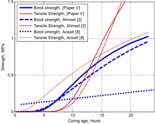
The results presented in [Paper IV-V] are used as a basis for recommendation of minimum ages of shotcrete at the time of blasting, exemplified with the recommendations for 100 mm thick shotcrete that are compiled and presented in Table 3.5. Three different shotcrete types are included in Table 3.5, with their development of bond and tensile strength shown in Figure 3.3. The results from [8] are given for comparison as representative for slow hardening shotcrete with waterglass (Sodium silicate) and low temperature curing. It is recommended [Paper II] that the maximum allowable PPVs at the interface between shotcrete and rock are 250 and 500 mm/s within 0–1 day and >1 day, respectively. The results in Table 3.5 are calculated for detonations of 0.5, 1.0, 2.0 and 3.0 kg of explosive at 2.2, 3.0 and 5.0 m from shotcrete on a granite rock surface. The results are obtained from comparison with the bond and tensile strengths given in Figure 3.3, see [Paper V].
3.3.SHOTCRETE VIBRATION LIMITS
19
Table 3.4: Recommended minimum safe distance for fully hardened shotcrete and detonation of Q = 2 kg explosives, from [2].
Rock and load characteristics Shotcrete thickness
100 mm 50 mm 25 mm
Erock= 16 GPa and f = 1265 Hz 1.8 m 1.0 m 0.7 m
Erock= 40 GPa and f = 2000 Hz 2.5 m 1.5 m 0.8 m
Erock= 40 GPa and f = 2500 Hz [10] 3.5 m 1.9 m 1.2 m
Figure 3.2: Compiled minimum safe distances from detonation of Q= 2 kg. Dependence of load frequency f and rock modulus of elasticity E, [2].
0 25 50 100 0.8 1 1.2 1.4 1.6 1.8 2 2.2 2.4 2.6 Shotcrete thickness, mm D is tan ce f ro m t he c har ge c en tr e, m f = 1265 Hz, E = 16 GPa f = 2000 Hz, E = 40 GPa
CHAPTER 3.IMPACT VIBRATION LIMITS AND GUIDELINES
20
Table 3.5: Recommended minimum ages in hours for 100 mm thick shotcrete of three types. The strength development is shown in Figure 3.3.
Distance form explosive
2.2 m 3.0 m 5.0 m
Explosives: 0.5kg 1.0kg 2.0kg 0.5kg 1.0kg 2.0kg 3.0kg 0.5kg 1.0kg 2.0kg
Ahmed [2] 12 18 * 10 13 21 - 7 9 12
Ansell [8] >24 >48 * 24 >24 >48 - 9 21 >24
[Paper V] - - - - 12 15 23 - - -
* Not possible to obtain a sufficiently high bond strength. - Data not calculated.
Figure 3.3: Bond and tensile strength vs curing age for the young and hardening shotcrete types referred to in Table 3.5.
0 5 10 15 20
0 0.5 1 1.5
Curing age, hours
Str en gt h, M P a
Bond strength, [Paper V] Tensile Strength, [Paper V] Bond strength, Ahmed [2] Tensile Strength, Ahmed [2] Bond strength, Ansell [8] Tensile Strength, Ansell [8]
4
In situ and laboratory investigations
This section describes laboratory tests performed to simulate stress waves travelling through the rock, striking at a shotcrete-rock interface. The tests, thoroughly described in [2] and [Paper II-IV], give data for the investigation and demonstration of how stress waves and structural vibrations are connected. The results are also used for evaluation of the elastic stress wave model, see [Paper III] and Chapter 5, and the bond strength development for shotcrete. In addition, a non-destructive test using the impact resonance method to determine Poisson’s ratio at early ages is presented. An earlier laboratory test series and two in situ vibration measurement programs used for comparison and verification of the numerical results presented within the project are also summarized.
4.1 Laboratory testing
4.1.1 Bond failure
An attempt to simulate stress wave propagation through good quality granite, from an explosive charge towards a shotcreted rock surface, has been performed in the laboratory [Paper II]. An experiment was set up with P-wave propagation along a concrete bar, with properties similar to those of hard rock. Cement based mortar with properties that resembles shotcrete was applied on one end of the bar and a hammer impacted the other. For practical reasons, the rock was made of concrete with similar dynamic properties as those of rock and the shotcrete was substituted with cement mortar cast onto one of the quadratic end-surfaces of the concrete bar. The mortar thus formed a slab with the same cross section as the bar, bonding to the end-surface of the bar that corresponds to the rock surface in a tunnel. The layout of a test-bar suspended by cables is shown in Figure 4.1. The concrete beam dimensions and its material properties are given in [Paper II]. A series of tests with 50 and 100 mm thick slabs of shotcrete (mortar) has been carried out where the bar with shotcrete was subjected to different intensity impacts until failure. The tests were performed at shotcrete ages of 6 and 18 hours, as described in Table 4.1, also giving compressive strength of 150 mm cubes, the propagation velocity c, and the bond strength between concrete and shotcrete (mortar). The latter was determined from laboratory pull-out tests where mortar was
Chapter
CHAPTER 4.IN SITU AND LABORATORY INVESTIGATIONS
22
cast on concrete plates with pre-drilled ϕ95 mm cores that were pulled out from the bottom of the plates using a testing device able to register the pull-out force [27].
Figure 4.1: Schematic view of the set-up for hammer impact tests, from [Paper II]. Table 4.1: Test series for bond testing, from [Paper II].
Specimen type Shotcrete thickness, mm Age, hours Density, kg/m3 Compressive strength, MPa Shotcrete c, mm/s Bond strength [27], MPa B-S50-6 50 6 2284 0.60 1150 0.1 B-S50-18 50 18 2242 17.0 2266 0.7 B-S100-6 100 6 0.1 B-S100-18 100 18 2268 21.6 2266 0.7
The measurements were divided into two parts; verification of the properties of the test-bar and the search for failure limit PPV for the early age shotcrete. The first part was done to verify that the behaviour of the suspended test-bar is close to that of a free-free bar. Further details are presented in [Paper II]. The acceleration time history and acceleration–frequency spectra for the four points are shown in Figure 4.1, and of specimen B-S100-18 plotted in Figure 4.2. All acceleration time histories and spectra that can be drawn from the performed measurements are similar to these figures. The results from the measured acceleration show two waves that propagate in opposite directions in the bar due to wave reflections, i.e. the incident wave and the reflected wave overlaps. Thus, the acceleration at the middle point (p2)
is the sum of the two opposing waves. When a propagating wave reaches the interface between shotcrete and rock, a part of the wave energy will be transmitted into the shotcrete while the other part reflects back into the rock. This proportion depends on the impedance ratio between rock and the shotcrete, see [Paper II]. The transmitted wave propagates in the shotcrete and reaches the free surface where it is reflected back while doubling the acceleration, see e.g. Dowding [36].
4.1.LABORATORY TESTING
23
Figure 4.2: Measured acceleration time history and frequency spectra, for an impact velocity of 1.85 m/s, from [2]. 0 0.02 0.04 0.06 0.08 0.1 -1500 -1000 -500 0 500 1000 1500 A ccel e ra tion, m /s 2 Time,s 0 1000 2000 3000 4000 5000 0 50 100 150 200 250 |Y (f )| Frequency, Hz 0 0.02 0.04 0.06 0.08 0.1 -1500 -1000 -500 0 500 1000 1500 Time,s A ccel e ra tion, m /s 2 0 1000 2000 3000 4000 5000 0 50 100 150 200 250 Frequency, Hz |Y (f )| 0 0.02 0.04 0.06 0.08 0.1 -1500 -1000 -500 0 500 1000 1500 A cc e le ra tio n ,m /s 2 Time,s 0 1000 2000 3000 4000 5000 0 50 100 150 200 250 |Y (f )| Frequency, Hz 0 0.02 0.04 0.06 0.08 0.1 -1500 -1000 -500 0 500 1000 1500 Time,s A ccel e ra tion, m /s 2 0 1000 2000 3000 4000 5000 0 50 100 150 200 250 Frequency, Hz |Y (f )| p1 p2 p3 p4 Im pact ing ham m er C onc ret e ba r Gr out ed c oncr et e B-S100 -18
CHAPTER 4.IN SITU AND LABORATORY INVESTIGATIONS
24
It was observed that shotcrete is rigidly tied to the concrete surface until sudden failure occurs. Similar bond behaviour has been observed during testing, [27]. The bond failure was due to the induced stress wave at the opposite end of the bar through the impact of a steel hammer. The tests simulated incoming stress waves, giving rise to inertia forces caused by the accelerations acting on the shotcrete. These will in turn yield stresses at the shotcrete-rock (slab-bar) interface, which may cause bond failure. It is also possible that shotcrete may fail due to low tensile strength, i.e. a failure within the slab.
4.1.2 Poisson’s ratio
There are few investigations that present information on Poisson’s ratio at early age, and thus it is often reported in the literature that this parameter is insensitive to age, see [105 and 71]. Most published results indicate that the measured Poisson’s ratio showed practically the same value for all ages and curing conditions. The majority provides a small number of values for Poisson’s ratio at ages from 12 to 30 hours. To date, there is no information given in the Eurocode 2 [40] about how to specify Poisson’s ratio at early ages. Although some experimental results [105] show increasing values of Poisson’s ratio with age during the first 12 hours, e.g. up to about 25%, this is often considered as an approximately constant value. There are however two important exceptions to this, the studies performed by Byfors [29] and Mesbah [92], who described a significant decrease in Poisson’s ratio at very early ages. A decreasing trend of Poisson’s ratio from approximately 0.4 to 0.1 during the first 10-15 hours, at a compressive strength of about 1 MPa, [29]. After this, Poisson’s ratio increases with strength growth. These observations are also in agreement with the results from an investigation on high performance concrete using the pulse velocity method [92] where Poisson’s ratio decreased during a short period of about 9 to 18 hours, reaching a value of 0.14 then increasing to its final values after 7 days. In numerical tests, it was found here that this parameter has a significant effect of the numerical results for early age concrete and therefore, a small scale laboratory test was performed. A non-destructive test was carried out using the impact resonance method where a freely supported (hanging) test specimen is struck with a small impactor and the specimen response is measured using an accelerometer on the specimen. In this test, the longitudinal, transverse and torsional frequencies of the concrete prism at various times after casting were measured so that Poisson’s ratio could be calculated, according to testing standard [14]. It should be noted that the same test method was used by Nagy [96], presenting results on which the relation between static and dynamic elastic modulus used in the initial studies [10 and 8] was based. Three accelerometers were positioned on the specimen, as shown in Figure 4.3, enabling the recording of particle accelerations for the three fundamental transverses, longitudinal and torsional resonance frequencies of the concrete specimen. The fundamental frequencies for the three modes of vibration are obtained by proper location of the impact point and the accelerometers, according to [14]. The recording time was approximately 0.03 s with a sampling frequency of 9600 Hz, the highest possible. The recorded signals of impact were low-pass filtered (Bessel filter with 1200 Hz sample rate) before the data was sampled, as described in [Paper II]. The results show similar decreasing trend as in [29 and 92], here shown in Figure 4.4. This figure demonstrates the evolution of Poisson’s ratio as function of time for two test prisms. It can be seen that during the first 12 hours, a significant variation of Poisson’s ratio occurs, and thereafter stabilizes.
4.1.LABORATORY TESTING
25
Figure 4.3: The suspended prism and the position of the accelerometers.
Figure 4.4: Poisson’s ratio versus age, example from laboratory testing [Paper VI].
Thus, the variation of Poisson’s ratio (vc) will from now on be assumed to follow the two
regression equations given in [29], i.e.: 0.148 . f
cc < 1 MPa (4.1)
and:
0.128 . fcc > 1 MPa (4.2)
where fcc is the mean compressive cube strength.
![Table 1.1: A compilation of terminology for young and early age concrete, from [4].](https://thumb-eu.123doks.com/thumbv2/5dokorg/5437098.140457/15.892.106.791.481.775/table-compilation-terminology-young-early-age-concrete.webp)
![Figure 2.1: Approximate strain rate associated with various cases of loading, from [6]](https://thumb-eu.123doks.com/thumbv2/5dokorg/5437098.140457/22.892.131.766.514.894/figure-approximate-strain-rate-associated-various-cases-loading.webp)
![Figure 2.2: Strain rate effects on the concrete compressive strength, from [19].](https://thumb-eu.123doks.com/thumbv2/5dokorg/5437098.140457/23.892.208.684.108.481/figure-strain-rate-effects-concrete-compressive-strength.webp)
![Figure 2.4: Frequencies and amplitudes for different dynamic loads, according to [50]](https://thumb-eu.123doks.com/thumbv2/5dokorg/5437098.140457/24.892.145.745.496.850/figure-frequencies-amplitudes-different-dynamic-loads-according.webp)
![Table 3.1: A comparison of some national standards and specifications for vibrations close to young and hardening concrete, from [Paper I]](https://thumb-eu.123doks.com/thumbv2/5dokorg/5437098.140457/28.892.115.787.255.617/table-comparison-national-standards-specifications-vibrations-hardening-concrete.webp)
![Table 3.3: Recommended PPV damage limits for early age concrete, from finite element calculations presented in [Paper VI]](https://thumb-eu.123doks.com/thumbv2/5dokorg/5437098.140457/29.892.109.787.911.1111/table-recommended-damage-limits-concrete-element-calculations-presented.webp)
![Figure 3.2: Compiled minimum safe distances from detonation of Q= 2 kg. Dependence of load frequency f and rock modulus of elasticity E, [2]](https://thumb-eu.123doks.com/thumbv2/5dokorg/5437098.140457/31.892.167.706.440.876/figure-compiled-minimum-distances-detonation-dependence-frequency-elasticity.webp)
![Figure 4.1: Schematic view of the set-up for hammer impact tests, from [Paper II].](https://thumb-eu.123doks.com/thumbv2/5dokorg/5437098.140457/34.892.114.798.176.442/figure-schematic-view-set-hammer-impact-tests-paper.webp)
![Figure 4.2: Measured acceleration time history and frequency spectra, for an impact velocity of 1.85 m/s, from [2]](https://thumb-eu.123doks.com/thumbv2/5dokorg/5437098.140457/35.892.110.774.106.1065/figure-measured-acceleration-history-frequency-spectra-impact-velocity.webp)
