I
Master Thesis
Electrical Engineering
Thesis No: MEE10:76
Sep 2010
Analysis of Network Security Threats and
Vulnerabilities by Development & Implementation of a
Security Network Monitoring Solution
Nadeem Ahmad (771102-5598)
M. Kashif Habib (800220-7010)
School of Engineering
Department of Telecommunication
Blekinge Institute of Technology
SE - 371 79 Karlskrona
II
University Supervisor:
Karel De Vogeleer
E-post:
karel.de.vogeleer@bth.se
School of Engineering
Blekinge Institute of Technology (BTH)
SE - 371 79 Karlskrona, Sweden
University Examiner:
Professor Adrian Popescu
E-post:
adrian.popescu@bth.se
Internet : www.bth.se
Phone : +46 455 38 50 00
Fax : +46 455 38 50 57
This report is to be submitted to Department of Telecommunication Systems, at School of Electrical Engineering, Blekinge Institute of Technology, as a requisite to obtain degree in Master’s of Electrical Engineering emphasis on Telecommunication/Internet System (session 2008-2010).Contact information
Author(s):
M. Kashif Habib
E-post: muhb08@student.bth.se, m_kashif_habib@hotmail.com
Nadeem Ahmad
III
Acknowledgement
In The Name of ALLAH, the Most Beneficial and Merciful. We are very thankful to all those who have helped us in giving us support throughout performing our thesis. First of all we would like to thank our university supervisor, who cultivated our mind with skills, providing us this opportunity to complete master degree thesis with complete support and guidance during entire period. His comments and proper feedback made us achieve this goal. We are both extraordinary thankful to our parents who had been praying during our degree studies and in hard times. Special thanks to Mikeal Åsman and Lena Magnusson for complete assistance in study throughout our master degree.
IV
Abstract
Communication of confidential data over the internet is becoming more frequent every day. Individuals and organizations are sending their confidential data electronically. It is also common that hackers target these networks. In current times, protecting the data, software and hardware from viruses is, now more than ever, a need and not just a concern. What you need to know about networks these days? How security is implemented to ensure a network? How is security managed? In this paper we will try to address the above questions and give an idea of where we are now standing with the security of the network.
V
TABLE OF CONTENTS
Chapter 1
INTRODUCTION
1.1 Motivation
1
1.2 Goal/Aim
1
1.3 Methodology
2
Chapter 2
NETWORKS AND PROTOCOLS
2.1 Networks
3
2.2 The Open System Interconnected Model (OSI)
3
2.3 TCP/IP Protocol Suite
7
2.3.1 Link Layer
9
2.3.1.1 Address Resolution Protocol (ARP)
9
2.3.1.2 Reverse Address Resolution Protocol (RARP)
10
2.3.2 Internet Layer
10
2.3.2.1 Internet Protocol (IP)
10
2.3.2.2 Internet Control Message Protocol (ICMP)
13
2.3.2.3 Internet Group Message Protocol (IGMP)
15
Security Level Protocols
16
2.3.2.4 Internet Protocol Security (IPSec)
16
2.3.2.4.1 Protocol Identifier
16
2.3.2.4.2 Modes of Operation
17
2.3.3 Transport Layer Protocol
19
2.3.3.1 Transmission Control Protocol (TCP)
20
2.3.3.2 User datagram Protocols (UDP)
21
Security Level Protocols
21
2.3.3.3 Secure sockets layer (SSL)
21
2.3.3.4 Transport Layer Security (TLS)
21
2.3.4 Application Layer Protocol
22
2.3.4.1 Simple Mail Transfer Protocol (SMTP)
23
2.3.4.2 File Transfer Protocol (FTP)
23
Security Level Protocols
24
2.3.4.3 Telnet
24
Chapter 3
NETWORK SECURITY THREATS AND VULNERABILITIES
3.1 Security Threats
26
3.2 Security Vulnerabilities
26
3.3 Unauthorized Access
27
3.4 Inappropriate Access of resources
28
3.5 Disclosure of Data
28
VI
3.7 Disclosure of Traffic
28
3.8 Spoofing
29
3.9 Disruption of Network Functions
29
3.10 Common Threats
30
3.10.1 Errors and Omissions
30
3.10.2 Fraud and Theft
30
3.10.3 Disgruntled Employees
30
3.10.4 Physical and Infrastructure
31
3.10.5 Malicious Hackers
31
3.10.6 Malicious Application Terms
32
Chapter 4
NETWORK SECURITY ATTACKS
4.1 General Categories of Security Attacks
33
4.1.1 Reconnaissance Attack
36
4.1.1.1 Packet Sniffers
37
4.1.1.1.1 Passive Sniffing
37
4.1.1.1.2 Active Sniffing
38
4.1.1.2 Prot Scan & Ping Sweep
39
4.1.1.3 Internet Information Queries
40
4.1.2 Access Attack
40
4.1.2.1 Password Attack
40
4.1.2.1.1 Types of Password Attack
41
4.1.2.2 Trust Exploitation
41
4.1.2.3 Port Redirection or Spoofed ARP Message
42
4.1.2.4 Man-in-the-Middle Attack
42
4.1.3 DOS Attacks
43
4.1.3.1 DDOS
43
4.1.3.2 Buffer Overflow
44
4.1.4 Viruses and Other Malicious Program
44
Chapter 5
SECURITY COUNTERMEASURES TECHNIQUES AND TOOLS
5.1 Security Countermeasures Techniques
46
5.1.1 Security Policies
47
5.1.2 Authority of Resources
47
5.1.3 Detecting Malicious Activity
47
5.1.4 Mitigating Possible Attacks
47
5.1.5 Fixing Core Problems
47
5.2 Security Countermeasures Tools
47
5.2.1 Encryption
47
5.2.1.1 Overview
47
5.2.2 Conventional or Symmetric Encryption
48
5.2.2.1 Principle
48
5.2.2.2 Algorithm
49
VII
5.2.3 Public-key or Asymmetric Encryption
51
5.2.3.1 Principle
51
5.2.3.2 Algorithm
54
5.2.3.3 Key Management
54
Chapter 6
SECURITY SOLUTIONS
6.1 Applications Level Solutions
55
6.1.1 Authentication Level
55
6.1.1.1 Kerberos
55
6.1.1.2 X.509
55
6.1.2 E-Mail Level
55
6.1.2.1 Pretty Good Privacy (PGP)
56
6.1.2.2 Secure/ Multipurpose Internet Mail Extension (S/MIME)
57
6.1.3 IP Level
57
6.1.3.1 Internet Protocols Security (IPSec)
57
6.1.4 Web Level
58
6.1.4.1 Secure Sockets Layer/ Transport Layer Security (SSL/TLS)
59
6.1.4.2 Secure Electronic Transaction (SET)
60
6.2 System Level Solutions
62
6.2.1 Intrusion Detection System (IDS)
62
6.2.2 Intrusion Protection System (IPS)
64
6.2.3 Antivirus Technique
65
6.2.4 Firewalls
68
Chapter 7
SIMULATION / TESTING RESULTS
7.1 Overview
72
7.2 Goal
72
7.3 Scenario
72
7.4 Object Modules
73
7.5 Applications/Services
74
7.6 Task Assignments
74
7.7 Object Modules
75
7.8 Results
76
7.8.1 General Network
76
7.8.2 Firewall Based Network
78
7.8.3 VPN with Firewall
79
7.8.4 Bandwidth Utilization
80
Chapter 8
CONCLUSION AND FUTURE WORK
8.1 Conclusion
82
8.2 Future Work
82
- 1 -
Chapter 1
INTRODUCTION
1.1 Motivation
“In this age of universal electronic connectivity when world is becoming a global village, different threats like viruses and hackers, eavesdropping and fraud, undeniably there is no time at which security does not matter.
Volatile growth in computer systems and networks has increased the dependence of both organizations and individuals on the information stored and communicated using these systems. This leads to a sharp awareness of the need to protect data and resources to disclosure, to guarantee the authenticity of data and messages, and protection of systems from network-based attacks”. [1]
There are those who believe that security problems faced by home users are greatly overstated, and that the security only concerned about business computers that have significant data with them. And many believe that only broad band users or people with high speed connections need to be considered.
Truth is that majority of computer systems including business ones have not any threat about the data which they contains, rather these compromised systems are often used for practical purpose, such as to launch a DDOS attack in opposition to the other networks. [2]
Securing a network is a complicated job, historically only experienced and qualified experts can deal with it. However, as more and more people become agitated, there is a need of more lethargic people who can understand the basics of network security world.
Different levels of security are appropriate for different organizations. Organizations and individuals can ensure better security by using systematic approach that includes analysis, design, implementation and maintenance. The analysis phase requires that you thoroughly investigate your entire network, both software and hardware, from inside and outside. This helps to establish if there are or may be vulnerabilities. An analysis shows you a clear picture that what is in place today and what you may require for tomorrow. [3]
1.2 Goal/Aim
The main focus of this dissertation is to come up with a better understanding of network security applications and standards. Focus will be on applications and standards that are widely used and have been widely deployed.
- 2 -
1.3 Methodology
To achieve our goals we will investigate following parameters. Networks and protocols
Security threats and vulnerabilities Security attacks
Security countermeasures techniques and tools Security solutions
- 3 -
Chapter 2
NETWORKS AND PROTOCOLS
In this chapter we will describe the basic concept of data communication network. The network layer protocols are the major part in a communication network. This chapter includes the description of the role of network layer protocols in a communication model; it also explains the functional parameters of these protocols in different level of data communication. These parameters are in the form of protocol header fields. We will study the header field of these protocols and analyze that how an attacker can use or change these protocol header fields to accomplish his/her malicious goals. The in-depth study of the structure of OSI layer protocols & TCP/IP layer protocols can carry out this objective.
2.1 Network
The network consists of collection of systems connected to each other through any communication channel. The communication channel may consist of any physical “wired” or logical “wireless” medium and of any electronic device known as node. Computers and printers are some of the examples of nodes in a computer network and if we talk about the telecommunication network these may be mobile phones, connecting towers equipment and main control units. The characteristic of a node in the network is that; it has its own identity in the form of its unique network identification.
The main functionality of any network is to divide resources among the nodes. The network under certain rules finds resources and then shares it between the nodes in such a way that authenticity and security issues are guaranteed.
The rules for communication among network nodes are the network protocols. A protocol is the complete set of rules governing the interaction between two systems [4]. It varies for varying different working assignments between nodes communication.
2.2 The Open System Interconnected Model (OSI)
In 1997, The International Standard Organization (ISO) designed a standard communication framework for heterogeneous systems in network. As per functionality of communication system in open world, this system is called Open System Interconnection Model (OSI). The OSI reference model provides a framework to break down complex inter-networks into such components that can more easily be understood and utilized [4]. The purpose of OSI is to allow any computer anywhere in the world to communicate with any other, as long as both follow the OSI standards [5].
The OSI reference model is exploited into seven levels. Every level in OSI Model has its own working functionality; these levels are isolated but on the other hand cascaded to each other and have communication functionality in a proper flow between them. With reference to above standard communication framework, this set of layers known as OSI layers. Functionality of each layer is different from each and each layer has different level and labels. (Shown in fig 2.1)
- 4 -
Layer
Layer
7
7
6
6
5
5
4
4
3
3
2
2
1
1
Fig 2.1: OSI Reference Model Layer Architecture
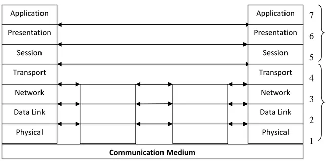
On the other hand if we see the system architecture of OSI, three level of abstraction is explicitly recognized; the architecture, the service specifications, and the protocols specifications (see fig 2.2) [5]. The OSI service specifications are responsible for specific services between user and system in a specific layer. Parallel OSI protocol specifications are responsible that, which type of protocol is running against the specific communication service. So it is clear that the combination of these two parts become OSI system architecture.
Fig 2.2: OSI System Architecture
It is patent that the OSI reference model consists of seven layers and each layer offers different functionalities, different services with different protocols. Whereas each layer, with the exception of the
OSI Reference Model
OSI Services OSI Protocols Communication Medium Data Link Physical Presentation Session Transport Network Application Data Link Physical Presentation Session Transport Network Application
- 5 -
lowest, covers a lower layer, effectively isolating them from higher layers functions.[6].Similarly the design principle of information hiding; the lower layer are concerned with greater level of details, upper layer are independent of these details. Within each layer, both services are provided to the next higher layer and the protocol to the peer layer in other system are provided [8] (seefig 2.3). Therefore we may say that as any change occurs in any layer-N, then it may effect only on its lowest layers-N-1. Due to isolation, the higher layers-N+1 is not affected or it can say that remaining reference model will not effect.
Fig 2.3: OSI Framework Architecture
Physical Layer
The lowest layer in OSI model is Physical Layer; it facilitates the connectivity between system interface cards and physical mediums. This layer understands and transforms electrical/electronic signals in the form of bits. So that it administrates physical “wire” and/or logical “wireless” connection establishment between the hardware interface cards and communication medium; example of physical layer standard includes RS-232, V.24 and V.35 interfaces [6].
Data Link Layer
In OSI Reference Model the Data Link Layer is the second layer. Data Link layer is responsible for control methods which provides proper format of data and it can access data flow errors in physical
Layer N Total Communi -cation Function Decompose Information Hiding Service to Layer N+1 Service from Layer N-1 Protocol with Peer Layer N Layer 1 (Physical) Layer N Layer 1 (Application) OSI-Standards (NW Management, Security)
- 6 -
layer. The data format in data link layer is in the form of frames. Therefore we say that the data link layer is responsible for defining data formats to include the entity by which information is transported. Error control procedures and other link control procedures may occur in physical layer [6]. Like cyclic redundancy check (CRC); the error checking mechanism that run at the time of transmission of a frame from source side. The same mechanism will run at the destination side if they found any difference after comparison then receiver makes a request to source to send that frame again.
Data link layer is responsible for following service [7]. Encapsulation
Frame Synchronization Logical link control (LLC)
o Error control o Flow control
Media Access Control (MAC) o Collision Detection o Physical Addressing
The data link layer is further subdivided into two layers, Logical link Control (LLC) and Media Access Control. The logical link control is responsible for flow control and error detection in data. Whereas media access control is responsible for controlling the traffic congestion and physical address reorganization.
Network Layer
The third layer in OSI Reference Model is the Network Layer. This layer is responsible to make a logical connection between source and destination. The data at this layer is in the form of packets. The network layer protocols provide the following services
Connection mode:
The network layer has two types of connection between source and destination, first one is known as connectionless communication which does not provide connection acknowledgement. The example of connectionless communication is Internet Protocol (IP). The second type of connection is connection-oriented which provides connection acknowledgement. TCP is an example of this connection.
IP Addressing:
In computer networks every node has its own unique ID. By this unique ID sender and receiver always make right connection. This is because of the functionality of network layer protocol, which has source address and destination address in their header fields. So there is less chance of packet loss, traffic congestion and broadcasting.
Transport Layer
The fourth layer in OSI reference model is Transport Layer. It contains two types of protocols, first is Transport Control Protocol (TCP) which is connection oriented protocol and supports some upper layer protocols like HTTP and SMTP. The second is User Datagram Protocol (UDP) which is a connection less protocol. Like TCP it also supports some upper layer protocols such as DNS, SNMP and FTP. The main thing in transport layer protocols is that they have port addresses in their header fields.
- 7 -
Session Layer
The fifth layer in OSI Reference Model is Session Layer. The Session Layer is responsible for session management i.e. start and end of sessions between end-user applications [7]. It is used in applications like live TV, video conferencing, VoIP etc, in which sender establishes multiple sessions with receiver before sending the data. Session Initiation protocols (SIP) is an example.
Presentation Layer
The sixth layer in OSI Reference Model is Presentation Layer. This layer is responsible for presentation of transmitted/received data in graphical mode. Data compression and decompression is the main functionality of this layer. The data encryption is done before transmission in presentation layer.
Application Layer
The seventh and the last layer of OSI Reference Model is Application Layer. This layer organizes all system level applications like FTP, E-mail services etc.
2.3 TCP/IP Protocol Suite
The TCP/IP Protocol Suite was developed before OSI reference model [9]. The OSI reference model consists of seven layers whereas TCP/IP protocol suite has only four layers (fig 2.4) [10]. In comparison to OSI reference model, TCP Suite has high level of communication traffic awareness between sources to destination. The TCP/IP Suite has administrative communication controlled and reliable data processing. It has dozens of layer components and communication set of rules which provide reliable service performance and data security [11].
Each layer in TCP/IP suite is responsible for a specific communication service and all these layers are cascaded and support each other (fig 2.5) [11]. The main protocols of this suite are TCP and UDP, which exist in transport layer. TCP is an acknowledgeable protocol that provides reliability in data transmission while UDP is non acknowledgeable protocol and is used in data streaming services like video conferencing, VOIP, etc.
- 8 -
The layer structure of TCP/IP suite is similar to OSI Model. In TCP/IP Suite the Link Layer covers the last two layers (physical and data link layer) of OSI model. Presentation and Session Layers of OSI model
ARP Hardware Interface RARP
ICMP IP IGMP TCP UDP Transport Layer Network Layer Link Layer Media Application Layer
Ping Telnet FTP SMTP Tracrt DNS SNMP FTP
Fig 2.5: Different Layers Protocols in TCP/IP suite Application Network Access / Link Internet Transport Presentation Application Session Physical Data Link Network Transport 7 6 5 4 3 2 1
OSI Model TCP/IP Suite
NOT Present
- 9 - do not exist in TCP/IP protocol suite. [12]
2.3.1 Link Layer
This layer is also known as data link layer or network interface layer. Link layer interfaces the network interface card and the communication medium. The important role of link layer is address resolution that provides mapping between two different forms of addresses with ARP and RARP protocols (see fig 2.6) [11]. For proper functionality; it has complete information of network interface cards, i.e. driver details and kernel information. It interprets between two systems in network for the sake of information of source address and destination address from software address to hardware address to send information on physical medium, because the kernel only recognizes the hardware address of network interface cards not the IP address or Physical address. Address resolution Protocols (ARP) translates an IP Address to a Hardware Address whereas Reverse Address Resolution Protocol (RARP) converts a hardware address to IP Address [6]. (See fig 2.6)
2.3.1.1 Address Resolution Protocol
The interpretation of data transmitted to communication medium from network layer depends on ARP and RARP link layer protocols. Network layer has source and destination address which is also called the logical address or 32-bits of IP Address, but before sending the information on a network via communication medium it is required to change this address IP address into 48-bits of hardware address which is also called Ethernet address or MAC Address. The reason for changing the address is that, the communication medium is directly connected to the Ethernet interface cards and it may assess the data via serial communication lines [6].
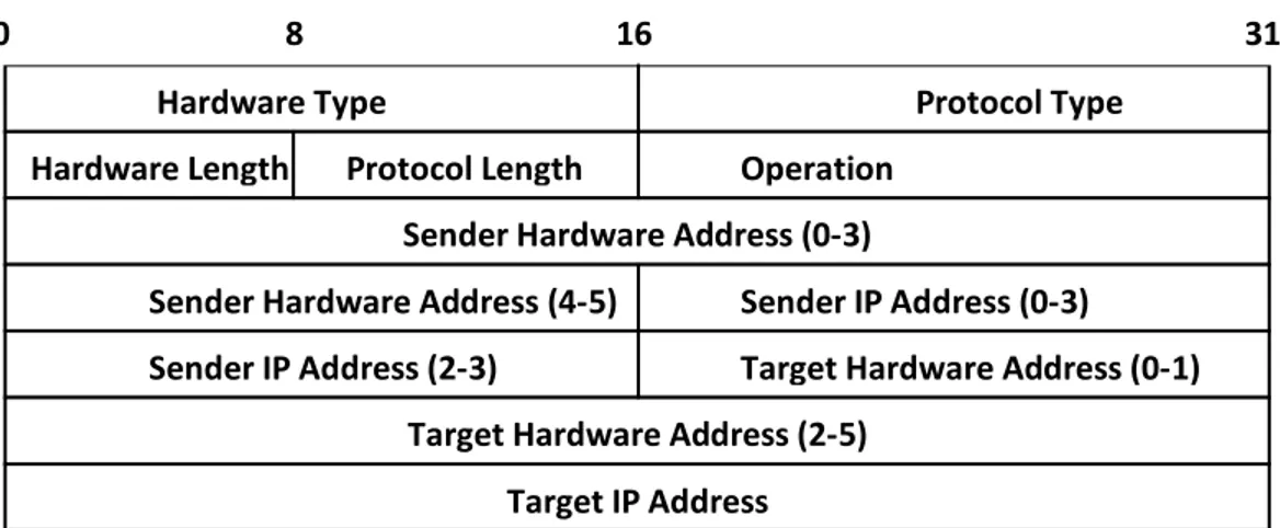
ARP operation; a network device during transmission in a communication medium performs sequence of operations [11]. Packet format of ARP is also clarified this (fig 2.7) [6].
o ARP request: A broadcast request in the form of Ethernet frames for the whole network. Request is basically a query for getting a hardware address against an appropriate IP.
o ARP reply: Appropriate hardware address generates a send back rep; response to sender against its query, in the form of its hardware address with its IP address.
o Exchange: request-reply information.
32-bits, Internet address
48-bits, Ethernet address
RARP ARP
- 10 -
o
Send: IP datagram to destination host.In Data link layer, Ethernet and Token ring have the same hardware length, as well if it sends a query request then operation has 1 notation and in query response that has changed to in notation of 2.
2.3.1.2 Reverse Address Resolution Protocol
RARP packet format and operation is similar to ARP operation but has reverse working functionality. RARP generates a query for IP address against appropriate MAC address. This design is for diskless workstation which has a big usage in corporate environment [11]. In this scenario the diskless workstation can get their IP address from server against their specific hardware addresses.
2.3.2 Internet Layer
The second layer of TCP/IP suite protocol structure is Internet or network layer. It generates a service request to Data Link layer protocol and provides services against Transport layer application request.
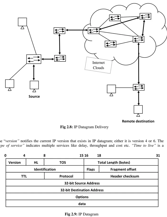
The role of internet layer protocol (IP) is very important in internetworking data transmission and in receiving prospects; datagram delivery is the main task of this layer. (Fig 2.8)
2.3.2.1 Internet protocol
Internet protocol is an important protocol of the internet layer as well for the whole internetworking communication. The protocol structure of internet layer is IP datagram and each IP datagram consists of the source IP address and destination IP address which is of 32-bit physical address. [11]. Consider the layer traffic scenario; it receives UDP/TCP segment request form transport layer and add some layer information tags as a prefix and convert it into IP datagram [6]. That is concerned with the exact datagram delivery in the form of source and destination IP address. Figure 2.9 shows the whole datagram packet.
Hardware Type Protocol Type Hardware Length Protocol Length Operation
Sender Hardware Address (0-3)
Sender Hardware Address (4-5) Sender IP Address (0-3)
0 8 16 31
Target IP Address
Sender IP Address (2-3) Target Hardware Address (0-1) Target Hardware Address (2-5)
- 11 -
The “version” notifies the current IP version that exists in IP datagram; either it is version 4 or 6. The “type of service” indicates multiple services like delay, throughput and cost etc. “Time to live” is a
Remote destination Source
Source
Fig 2.8: IP Datagram Delivery
data
0 4 8 15 16 18 31 Version HL TOS Total Length (bytes)
Identification Flags Fragment offset
TTL Protocol Header checksum
32-bit Source Address 32-bit Destination Address
Options
Fig 2.9: IP Datagram
Internet Clouds
- 12 -
countdown counter that gradually down to zero
.
Two conditions exists here, either packet successfully reached to its destination or discarded before TTL reached to zero. If TTL counter reaches to 0 IP packet discarded from the network. The main advantage of TTL is that it overcomes the network traffic congestion issue. “Flags” contain 3 bit length as shown in IP datagram figure; they play an important role in successfully transmission of data packet at destination end.The 32-bit “source address” and “destination address” are the physical addresses of source and destination. These fields perform an efficient role to hitch-hike of IP traffic on network. A hacker can exploit the IP datagram by make some changes in it when the packet is traveling in communication medium in the form of hex code. Hacker can do this with the help of any network sniffing application or by use of TCP-dump and mapping application.
By using TCP-dump, malicious hacker can see the IP header datagram information and then can change the values by his/her malicious mind. Let’s take an example [13]
Examine the IP traffic with TCP-dump application gives all necessary information which could help in malicious act. This is the output of TCP-dump and it is in Hex-code for better understanding we may change it into binary and decimal code. From the figure 2.10 the information we can get; IP version (either 4 or 6), total length of IP packet, TTL of the packet, type of protocol either TCP or UDP, source and destination address.
4500 00b2 4ea6 2000 8006 ee3f c0a8 4803 c0a8 4804
4500 00b2 4ea6 2000 8006 ee3f c0a8 4803 c0a8 4804
Source IP Address 192.168.72.3 Dest. IP Addr 192.168.72.4 IP Ver. Total IP Packet Length TTL 128s Protocol TCP=6, UDP=11
- 13 -
2.3.2.2 ICMP Protocol
Some more and popular protocols in network layer of TCP/IP protocol suite are Internet Control Message Protocol (ICMP) and Internet Group Management Protocol (IGMP). These protocols worked together with the IP datagram protocol for their own working purpose. Therefore we can say that IP Protocol or its header used as a carrier for ICMP and IGMP protocols communication (fig 2.11) [6].
Timestamp request and timestamp reply are the examples of ICMP which are similar to echo request and echo reply. Additionally it provides sender timestamp request and receiver timestamp reply and difference is known as Round Trip Time (RTT) which is in milliseconds.
Exploiting this protocol is important for hackers because by changing or modifying in field he/she can easily divert the network traffic.
IP Header ICMP Message Data CRC
20 bytes IP datagram Type Code Checksum Sequence Number Optional
- 14 -
Echo request and echo reply are the functions of ICMP. With the help of ping command we can judge that our destination host is alive or not alive in the network, administrators used this for analyze the traffic. Some other ICMP types are expressed in the table below (Table. II.I) [11].
TABLE II.I: ICMP Message Types
Type Code Description Query Error
0 0 Echo reply * 3 Destination unreachable: * 0 Network unreachable * 1 Host unreachable * 2 Protocol unreachable * 3 Port unreachable *
5 Source route failed *
6 Destination network unknown *
7 Destination host unknown *
4 0 Source quench (elementary flow control) *
5 Redirect *
8 0 Echo request (ping request) *
11 Time exceeded:
0 Time to live equals 0 during transit (traceroute) *
1 Time to live equals 0 during reassembly *
12 Parameter problem:
0 IP header bad *
1 Required option is missing *
13 0 Timestamp request *
- 15 -
2.3.2.3 IGMP Protocol:
Internet Group Management Protocol (IGMP) looks like internet Control Message Protocol. It exists in Internet layer in TCP/IP protocol suite. ICMP datagram also encapsulates with IP datagram for communication in a network. It supports multicasting concept between a group of hosts and between multicasting supported routers, in a physical network, which is against broadcasting. For the working of
multicasting, it provides the familiarities, how a class D and IP address are mapped with the hardware or Ethernet address [11].
By using net state query with some of its parameters we can get multicasting report or routing tables of our own system which is associated with hardware interface like netstat –nr
Route Table
=========================================================================== Interface List
0x1 ... MS TCP Loopback interface
0x2 ...00 1a 73 c4 18 02 ... Broadcom 802.11b/g WLAN - Packet Scheduler Miniport
0x3 ...00 1b 38 8d af bb ... Intel(R) PRO/100 VE Network Connection - PacketScheduler Miniport 0x10005 ...00 15 83 16 c0 22 ... Bluetooth Device (Personal Area Network) #2
===================================================================== ===================================================================== Active Routes:
Network Destination Netmask Gateway Interface Metric 0.0.0.0 0.0.0.0 194.47.156.1 194.47.156.108 25 127.0.0.0 255.0.0.0 127.0.0.1 127.0.0.1 1 194.47.156.0 255.255.255.0 194.47.156.108 194.47.156.108 25 194.47.156.108 255.255.255.255 127.0.0.1 127.0.0.1 25 194.47.156.255 255.255.255.255 194.47.156.108 194.47.156.108 25 224.0.0.0 240.0.0.0 194.47.156.108 194.47.156.108 25 255.255.255.255 255.255.255.255 194.47.156.108 194.47.156.108 1 255.255.255.255 255.255.255.255 194.47.156.108 3 1 255.255.255.255 255.255.255.255 194.47.156.108 10005 1 Default Gateway: 194.47.156.1 =========================================================================== naah08@sweet: netstat -nr Kernel IP routing table
Destination Gateway Genmask Flags MSS Window irtt Iface 194.47.153.0 0.0.0.0 255.255.255.0 U 0 0 0 eth0 0.0.0.0 194.47.153.2 0.0.0.0 UG 0 0 0 eth0
IP Header IGMP message Date CRC
IP datagram
- 16 -
Microsoft Operating system is used in first output and in second Linux operating system is used. The output expression is little bit different
.
Security Level Protocols
2.3.2.4 IPSec Protocol
IPSec is an internet layer protocol which provides security at internet layer. The key principle of IPSec on internet layer is that, it provides the security to individual users at transparent level. It provides the data access authentication as well as data encryption on the same level.
IPSec covers three areas of security level, data encryption, traffic authentication and key management [14].
2.3.2.4.1 Protocol Identifier
The IPSec protocol has classified into two sub-level protocols on the basis of their different working algorithms [11].
o Authentication Header (AH)
o Encapsulation Security Payload (ESP)
IP header IP Pay load
IP header IP Payload
IP header IPSec header Secure IP Payload
Internet
- 17 -
The authentication header has massage authentication block in its header field for authentication of massage, whereas encapsulation security payload has one more block of data encryption with massage authentication. Its mean that ESP protocol has one more feature of encrypt the data with authentication. However both of IPSec protocols are used in the IP level security. Above figure 2.14 shows the security level architecture model.
2.3.2.4.2 Mode of Operations
There are two modes used in IPSec for secure data transmission [15]. o Tunnel Mode o Transfer Mode Authentication Protocol ESP Protocol Encryption Algorithm Authentication Algorithm Architecture Key Management (0)
- 18 -
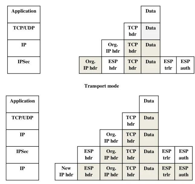
In “Transfer mode” first it provides the protection of existing upper layer protocols (tcp/udp) then provides the protection of existing IP payload (data). That is why ESP in transfer mode only encrypts and authenticates the IP data but does not protect the current IP header. Same as for AH protocol which provides the IP data or IP payload authentication and some selected part of IP header. But in “Tunnel mode” first it provides the protection to the existing IP packet then entertain the AH or ESP field in the IP packet. So ESP encrypts and authenticates the existing IP packet and then IP header in tunnel mode, same as for AH protocol which authenticate IP packet and then selected portion of IP header in tunnel mode[14]. (See fig 2.15)
There is another view expressed that is clear in diagram (fig 2.16) [14]. The dark color shows the old condition whereas white shows the current operation on appropriate protocol level.
Org. IP header TCP/IP header Data ( IP Payload )
Before AH & ESP
Org. IP header AH TCP/IP header Data ( IP Paylod ) ( Payload )
AH in Transport Mode
New IP header AH Org. IP header TCP/IP header Data ( Payload )
AH in Tunnel Mode
Org. IP header ESP header TCP/IP header Data ESP trailer ESP auth.
ESP in Transport Mode
Ne w IP header Org. IP header ESP header TCP/IP header Data ESP trailer
trailer
ESP auth
- 19 -
2.3.3 Transport Layer Protocol
Transport layer is the third layer in TCP/IP protocol suite which consists of two protocols, Transmission Control Protocol (TCP) and User Datagram Protocol (UDP). Different functionalities of these protocols comes up with different architectural models or headers. The main feature of Transport layer protocol is, introducing a new protocol header that was not present in lower layer protocols, that is a port concept. Working with Internet Protocol features; IP address and port function from transport layer protocol, against a specific services or application run on server that we get “socket” concept [16].
Org. IP hdr IPSec IP TCP/UDP Application Data Data ESP auth TCP hdr Transport mode ESP hdr ESP trlr Data TCP hdr Data TCP hdr Org. IP hdr Org. IP hdr Data Data ESP auth TCP hdr Org. IP hdr ESP trlr Data TCP hdr Data TCP hdr ESP hdr ESP auth Org. IP hdr ESP trlr Data TCP hdr ESP hdr New IP hdr IPSec IP TCP/UDP Application IP Tunnel mode
- 20 -
2.3.3.1 TCP Protocol
The Transmission Control Protocol (TCP) removes the existing drawbacks in internet protocol (IP); TCP makes connection before sending the data to destination that is why known as connection oriented protocol. Connection oriented functionality provides the reliable data transmission in communication. Similarly TCP notifies and remove errors with the help of error detection function which detects the errors during transmission. Acknowledgement from receiver shows that packet is successfully delivered to the destination that is why we say that TCP is a reliable protocol. If sender receives acknowledgement with error packet then sender sends again error-less packet toward receiver. Below is the figure showing some more features of TCP Protocol (fig 2.17) [6].
Source and Destination Port:
TCP protocol provides the source and destination services port. There are many applications, services and system processes that are associated with unique ports. By allocating specific ports with specific services on server end administrators can allow/deny system services to specific client or group of clients, i.e. web services.
Sequence and Acknowledgement Number:
The error detection is done by sequence number and acknowledgement number. The sequence number controls the sequence of sent packets, if sender receives any acknowledgment with error-packet then sender once again send error-less error-packet so that maintain the exact sequence number of the packet.
Code bits or flag indication:
There are six different flags indicator in TCP header which identifies different functions in TCP packet. Following are six flags [6].
Destination Port Source Port
Sequence Number Acknowledgement Number
Window
Checksum Urgent Pointer
Options Padding U R G A C K P S H R S T S Y N F I N Resr. H. len 0 3 7 15 16 31 Fig 2.17: TCP Header
- 21 -
1) URG Bit: This flag indicates the urgent data request; it assigns higher priority to urgent packets. 2) ACK Bit: This flag indicates that the datagram has an acknowledgement of previous packet or
that the datagram contain some specific acknowledgement number value. 3) PSH Bit: This flag indicates push bit. It work against with URG bit.
4) RST Bit: RST bit indicates reset request for connection from sender to receiver. 5) SYN Bit: Synchronization of sequence numbers of TCP packet.
6)
FIN Bit: It is a notification shows that sender wants to stop the data.7)
Checksum: The checksum field in TCP header provides error detection in TCP packets. In prospective of network security. The above fields in TCP header are very important for any hacker. They can use these flags to achieve their malicious goal.2.3.3.2 UDP Protocol
Second protocol of transport layer is User Datagram Protocol (UDP). UDP is a connection less protocol i.e., it does not establish a connection between sender and receiver before sending the data. Many applications which does not require connection establishment before transmission uses UDP examples of applications are Mobile TV, VoIP etc.
As compared to TCP header UDP has very simple header as shown in Fig 2.18. UDP does not provide reliability of data [11] because of no acknowledgement flag. But infect UDP is faster than TCP and in some applications speed is more important than reliability like in VoIP Applications. However source port, destination port and checksum fields have same functionality as in TCP header which we have already described above.
Security Level Protocols
There are some protocols which provide security at transport layer. Protocols are: o Secure Socket Layer (SSL)
o Transport Layer Security (TLS) o Secure Shell (SSH)
0 15 16 31 Destination Port
Source Port
Data (if any)
Message Length Checksum
- 22 -
All above security protocols work on transport layer. Secure Shell (SSH) is a protocol that provides secure network communication channel at transport layer [14]. It is used in sever-client connection environment. Initially user authentication is done at both ends similar like in TCP communication where three-way handshake connection is establish before data transmission, then SSH makes a secure tunnel between server and client before communication starts. In SSH, the connection established on the base of SSH user and server authentication after this it provides a communication tunnel for data transmission (fig 2.19).
Similarly SSL and TLS provide security to web applications at transport level. (fig 2.20) [14].
2.3.4 Application Layer Protocol
Application layer consist of applications and processes that works above the transport layer. These applications and processes do work by using the network or remaining lower layer protocols between two or more host in a network as an application-to-application or process-to-process communication level [17].
It is clear that all application level protocols communicate on network through transport and internet level protocols (see fig 2.5).
Secure SSH Tunnel Client Application SSH entity TCP entity Client Application SSH entity
TCP entity Unsecure TCP connection
Fig 2.19: TCP Connection via SSH Tunnel
HTTP FTP SMTP
SSL or TLS TCP
IP
- 23 -
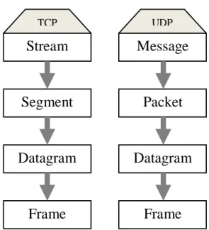
The applications on application layer which uses TCP protocols for communication in a network known as “Stream” applications on the other hand the application on application layer which uses UDP protocol known as “Message” applications and regarding these on transport layer “Segment” and “Packet” simultaneously.(fig 2.21)[18].
There are number of protocols at application layer we will discuss some of them regarding our project prospective, detail of these protocols will explain in next chapters.
2.3.4.1 SMTP Protocol
Electronic mail (e-mail) used almost everywhere in the world for communication of data in simple readable text or in GUI mode worked on application layer. The protocol used for Email is Simple Mail Transport Protocol (SMTP). This application protocol is laying on TCP protocol. Figure 2.22 shows the architecture of SMTP [11].
Mail transfer agent is responsible for transferring the e-mail messages from one system to another system on a local area network, but if email is delivered on wide area network then this agent is known as relay mail transfer agent. Similarly a user agent is responsible to send and receive electronic mail from mail-server to mail-client, i.e. Microsoft outlook express, Windows live mail etc [19].
2.3.4.2 FTP Protocol:
The protocol which is used for transferring the file form source to destination is called File Transfer Protocol (FTP). FTP transfers the file securely from source to destination across the local area network or wide area network. Before sending the data FTP makes secure connection between server and client on the basis of user authentication. Another feature of FTP protocol is that, it establishes dual TCP
Stream
Frame
Datagram
Segment
Application
Layer
NWAccess/
Link layer
Internet
Layer
Transport
Layer
TCPMessage
Frame
Datagram
Packet
UDP- 24 -
connections between server and client. One connection is for user authentication and second for data
transmission which provides reliable data transmission with authentication (See fig 2.23) [11].
Security Level Protocols
2.3.4.3 Telnet
Telnet is another famous application in prospective of network connection between two network hosts. Actually the telnet provides connection between a network host and any other network device. So we can say that it establishes a hardwired terminal connection from host to any other network device. Similarly in ftp connection it makes secure connection on the basis of host authentication on network
file system Server data transfer function Server Protocol interpreter Server User at terminal Control connection file system Client User Protocol interpreter User data transfer function User interface Data connection
Fig 2.23: FTP Connection Process
TCP port: 25 User at terminal User agent Queue of send mails Message transfer agent (Client) User at terminal User agent Queue of rec. mail (mailbox) Message transfer agent (Server) Receiver Sender
- 25 -
device or any other different operating system [11] that is why we say that telnet is an application level security protocol. User at terminal TCP/ IP Pseudo-Terminal driver Telnet Client Kernel TCP connection TCP/ IP Pseudo-Terminal driver Telnet Server Kernel Login shell
- 26 -
Chapter 3
NETWORK SECURITY THREATS AND
VULNERABILITIES
Network Security
When we talk about security, the first step is that how we define network security. If you ask from 10 different administrators about the definition of network security, you will probably get 10 different answers. However as its name suggest network security is the protection of networks, their applications or services against unauthorized access that prevents form modification, disclosure or destruction of data. It also assures that the network is performing correctly with no harmful side effects. [20] .This is admittedly, a very broad definition, but a general definition better prepares network administrators to deal with new types of attacks. Each organization defines its own security policy that describes the level of access, which is permitted or denied. So it is necessary for any organization to make such a security mechanism that is broad in scope and helps to deal with new types of attack
3.1 Security Threats
When talking about threat it can be any person or event that can cause the damage of data or network. Threats can also be natural for example wind, lightning, flooding or can be accidental, such as accidentally deletion of file.
3.2 Security Vulnerabilities
Vulnerabilities defined as the weakness in any network that can be exploited by a threat. Recently almost in all areas network technologies have been applied, such as banking, tax, E-Commerce. These applications are consist of different network devices and computers and it is very important to protect these applications and devices from malicious hackers so that chances to exploit the vulnerabilities may reduce. There are different hardware and software tools available in the market to protect against these attacks, such as firewalls, Intrusion Detection Systems (IDS), antivirus software and vulnerability scanning software. However the usage of these hardware and software cannot guarantee the network against attacks. “The only truly secure system is that which is powered off – and even then I have my doubts”, a quotation by a leading security expert [21]. According to the statistic from the reports of Computer Emergency Response Team/Coordination Center (CERT/CC), the number of exploited vulnerabilities increases dramatically [22], as shown in figure 3.1.
- 27 -
The impact of these threats and vulnerabilities points to the problems that result in disclosure, modification or denial of service. Below are some common threats to a network.
3.3 Unauthorized Access
If you are trying to gain a casual access to an unsecured wireless network, you can be arrested on spot, even if you have no criminal intent (other than stealing their bandwidth, of course). In Canada it is called theft of telecommunication [23]. The main advantage of any network is resource sharing. As a part of network we share different types of services like file and printer sharing due to shared resources any one can try to gain illegal access which can cause unauthorized access in network.
Password sharing, guessing and capturing are three common methods to gain illegal access. Password sharing and guessing are not a new mean of illegal access, there are different techniques for guessing a password.
Try default passwords. Try all dictionary words.
Try all short words, usually 1 to 3 characters long.
Try user’s personal number, mobile or phone number, home address, etc. By collecting user’s personal information like his/her birth day, family names.
Password capturing is a technique in which a hacker unknowingly steals user’s ID and password. Trojan horse program designed for this purpose that can capture the password. Below is some basic information that can prevent from unauthorized access.
Use strong passwords, contains at least 10 characters, contains at least one alpha, one numeric and one special character and use passwords that cannot contain dictionary words.
Use hardware and software firewall.
Use protection software against trojan, spyware, viruses and other malwares.
Carefully handle emails, usually viruses, spyware and other malware are distributed through emails that have an e-mail attachment.
- 28 -
3.4 Inappropriate Access of resources
Unauthorized access occurs when a user try to access a resource that is not permitted for it. This may occur because administrators not properly assigned the resources. It may also occur when privileges are not enough for a user. Company which have different departments and users, some users have inappropriate access to any network resources, mostly because the users are not from the same department or may be such users who are from outside the company. For example access to the accounts department data is inappropriate by the administrators for the users which belong to some other department. In this case administrators need to grant more access rights than a user needed.
3.5 Disclosure of Data
In any organization, some information which is either stored in a computer in the network or transmitted may require some level of confidentiality. Illegal access occurs when some one who is not authorized for that tries to read the data. It mostly happen because our information is not encrypted. There are different encryption schemes that are used today; we will discuss them in detail in next chapters.
3.6 Unauthorized Modification
Unauthorized modification of data is attack on data integrity. Any changing in data or software can create big problems; possibly can corrupt databases, spreadsheets or some other important applications. Any miner unauthorized change in software can damage the whole operating system or all applications which are related to that software and perhaps need to reinstall the software with all related applications.
This can be made by unauthorized as well as authorized users. Any change in the data or in application can divert the information to some other destinations. This information can be used by any outsider or hacker who can make some changes and again send to the destination.
Some reasons that can cause the unauthorized modification are [24]. Lack of encryption of data
The user which only requires read permission granted write permissions also. Access control mechanism that allow unnecessary write permission.
Lack of protection tools.
3.7 Disclosure of Network Traffic
When we talk about the data security we see that there are two different types of data, first type of data which is in system or computers and the second one which is transferring from machine to machine or share among the network users. These two types of data falls under two types of security, computer security and network security. The tools that are designed to protect the first type of data fall in computer security while the protection of data during transmission called network security. However we cannot distinguish a clear difference between these two types of security. As we discuss earlier that users know which type data is confidential it is also important to maintain the confidentiality of that data during its transmission. The data which can be compromised consist of passwords, e-mail messages, user names or any other useful information that could be used in future for negative purpose. Even e-mails and passwords which are stored in encrypted format in system, they can also be captured during transmission as a plaintext.
- 29 -
3.8 Spoofing of Network Traffic
During the transmission of data two things are important that assure the integrity of data, one is that, data is coming from a trusted host and second is that data contents are not altered or changed. Spoofing occurs when some one tries to pretend a trusted host. IP spoofing, Email spoofing and Web spoofing etc, are some types of spoofing. Messages transmitted over any network are consist of some address information, sender address and receiver address. An intruder or any hacker initially finds the IP address of a trusted host after compromising the host intruder can modify the message (packet header) so that it appears that the message is coming from that trusted host, as shown in figure 3.2. Same thing is in email spoofing that email looks like it came from Bob, but in reality, Bob did not send any email. Someone who was pretending to be Bon send the email. In web spoofing attacker create a web page like bank’s site or any email like hotmail web page but this web page is basically under the control of attacker so when you put the information it goes directly to the attacker. Several reasons are behind spoofing for example transmitting the network traffic in plaintext; do not use any message authentication code technique etc.
3.9 Disruption of Network Function
Basic function of any network is to share the resources and information. A disruption occurs when network did not provide the needed functionality on time. Interruption in network can affect on one type of functionality or on different functionalities.
Several reasons may lay behind the disruption on network
Network has no ability to detect the traffic, some time network goes down because of the useless traffic.
Network with single point of failure. Hardware failure.
Improper maintenance of network equipment.
Unauthorized access to network components may cause the changing in the
- 30 -
configuration of the components which also disrupt the network function.
3.10 Common Threats
Security is a continuous process and continuous war between attacker and defender. There is no security mechanism that exists which gives the complete protection. Several types of attacks can be eliminated but others will take their place. Implementation of a security mechanism some time cost too much therefore some administrators simply tolerate the expected losses and find it most cost effective solution.
Below we discuss some threats and associated losses with their expected growth. The list is not comprehensive some threats may have some common elements to other areas [25].
3.10.1 Errors and Omissions
There are lots of human unintentional errors which contribute in security problems. These can occur anywhere in the system. Sometime a small data entry error can cause the system crash, some of the error occurs during maintenance or installation which can also be a threat for security. Errors are an important threat to the integrity of data. These can produce unintentionally by data entry operators, system operators and developers. People mostly assume that the information coming from a computer system is more accurate. In past few years improvement in software quality reduces this threat.
3.10.2 Fraud and Theft
Integrity of data and confidentiality of information are the key features of any system. As information technology is increasing the threat of fraud and theft is also increasing. Attackers use daily new methods to exploit a system, these frauds involve in small amount money to large number of financial accounts. Financial systems are not only the target of hackers, systems which have any resources or controls are under attack by intruders, For Example University grading system, inventory system, human resource attendance system etc.
Threat of fraud and theft is both from insider or outsider. Majority of frauds are done by the insiders, because they are authorized users and they know the vulnerabilities in the system and they are in better position to commit a crime. Former employees of any organization may also a threat for company if administrators have not terminated their accounts properly and on time.
3.10.3 Disgruntled Employees
Disgruntled employees know better the flaws in network and they know which actions can cause the most damage. Downsizing in any organization can create a group of these people which have enough information and access to damage the system. Some examples of common sabotage are
Editing in data.
Modify the data incorrectly. Deleting the data.
Copy the data and further use it for wrong purpose. Spoil the hardware.
Administrators or system managers can decrease this threat by deleting the disgruntled employee’s accounts in a timely manner.
- 31 -
3.10.4 Physical and Infrastructure
Some time nature shows its power. It is also a reality that the loss occurs by the cause of natural disasters is more dangerous than viruses. Flood, fire, strikes, thunder storm, earthquakes, volcano eruptions, under water explosions, loss of communication are some of the examples, which sometime can cause the damage of whole physical and network infrastructure. We cannot forget the World Trade Center and Tsunami. Some time these disasters results in an unexpected way. For example in winter storm, even your whole computer network is fully functional but people cannot go to office due to the loss of infrastructure.
Fig 3.3.Shows the loss of infrastructure due to earthquake
3.10.5 Malicious Hackers
Any one who tries to gain illegal access to computer systems for the purpose of stealing or corrupting the data called hacker.
Hackers are real and most dangerous threat for the organizations which have big computer system network. They can be from inside the organization, outside the organization or form some other continent. They break the security of the systems, compromise the system and steal the data before any illegal access detected. Hacking can be of two types, ethical hacking and non ethical hacking. Non ethical hackers are those who are harmful for any organization. “It takes a thief to catch a thief”, a general phenomenon. If you want to repel a hacker attack first you have to know that how they think. Nowadays organizations are hiring hackers to find vulnerabilities in their network security mechanism. This type of hacking is called ethical hacking and such hackers are called ethical hackers. Time is changing now emerging trends in IT is leading us to a brighter day when computers can do even more for us than they are doing now. Theses changes may leave more vulnerability to exploit for the next generation of hackers.
- 32 -
3.10.6 Malicious Application Terms
Malicious programs are hard to detect. They may be installed personally on a machine or build widely as commercial software package. Viruses and other type of malicious programs have the ability to replicate themselves on several systems.
In the next chapter we will discuss about different types of network attacks, their weaknesses and different malicious programs.
- 33 -
Chapter 4
NETWORK SECURITY ATTACKS
4.1 General Categories of Security Attacks
To compromise between opening a system and lock it down so that no one can use it, is called security and any action that compromises the security is called a security attack. A system which is providing the services required by the user accurately and preventing the illegal use of system resources is called a secure system.
Attacks can be categorized into following basic categories [27].
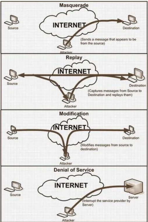
Interruption: For using the data or resources it is necessary that they are available 24/7 for the authorized parties, when and where they need it. Attack on the availability of data is called interruption. Availability can be affected by intentional or un-intentional acts. Examples of un-intentional acts are, accidentally system crash, deletion and overwriting of data and some time due to non human factors like flood, fires and earthquakes. Whereas destruction of infrastructure due to wars, strikes and some attacks by hackers that crashes the system, such as denial of service (DOS) and distributed denial of service (DDOS) attacks are the examples of intentional acts. Protection against availability attacks includes backup and restoration.
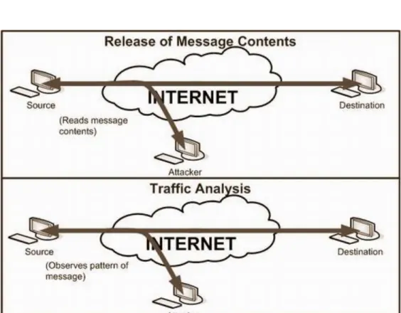
Interception: The core concept is that the data should be hiding from unauthorized users. If some one who is unauthorized to see private data, can see or copy the data that can further be used in intensive active attack. Such an attack is known as attack on confidentiality. Data integrity can be accomplished by strong authentication and strict access controls, because some time authorized users may also a threat for confidentiality of data. They can obtain another person‟s credentials.
Modification: Integrity of data deals with prevention of intentional or unintentional modification of data. Attack on integrity of data called modification. Different algorithms used for validation of data that can resist in alteration of data. Protection of data from modification is foremost concern than detection. Integrity of data could maintain at many layers of OSI system model.
Fabrication: Attack on authenticity called fabrication. Authenticity means that message is coming form the apparent source. It assures that you are who you say you are. User name and password is the most common way to achieve authentication, some other techniques are like smart cards and digital certificates.
- 34 -
On the basis of these four attacks we can further classify security attacks as passive attacks and active attacks. Passive attacks are only involved in monitoring of the information (interception). The goal of this attack is to obtain transmitted information. Two types of passive attacks are “release of message content” and “traffic analysis”. Passive attacks are