A modular TCP/IP stack for embedded systems with a tinyTimber interface
42
0
0
Full text
(2) A modular TCP/IP stack for embedded systems with a tinyTimber interface. Isak Rova Simon Aittamaa 27th June 2007.
(3)
(4) A BSTRACT Many of today’s embedded systems require internet connectivity for monitoring and control. Most of these systems use a stack implemented on specific hardware. This requires a lot of hardware specific software and might make it too time-consuming to exchange or upgrade the communication hardware. Using a standardized communication protocol such as the Point-To-Point-Protocol (PPP) makes it easier to exchange the hardware but also requires a software stack with support for PPP. EISLAB has been trying to find a viable solution for this problem but have been unable to do so. This project aims to provide a lightweight, modular and hardware independent software stack for end hosts with support for PPP. Additionally it should support a tinyTimber interface to facilitate real-time applications. The current stack implementation is portable enough to run on anything ranging from a regular home-PC to a PIC18 8-bit microcontroller. It should be trivial to port it to any architecture in that range. The memory requirements of the stack are low enough to run on the PIC18F6622 and still have most of the memory(> 70%) available to the application. While we initially planned to run the stack using tinyTimber on the PIC18 , we came to the conclusion that the limitations imposed by the architecture where too strict. This decision was made after porting tinyTimber to the PIC18. Since there is a tinyTimber interface for the stack it is quite possible to run the stack using tinyTimber on the PIC18. This however, is not recommended since it would consume most of the system resources. It’s worth noting that while the PIC18 is not a suitable architecture to run multithreaded tinyTimber there are other architectures that are more suited for this task, such as the ARM, that might use the tinyTimber interface to the stack. To be able to test the tinyTimber interface we also had to developed a version of tinyTimber that is capable of running on any POSIX compliant system. iii.
(5)
(6) P REFACE. This master thesis was conducted at EISLAB, Lule˚ a Tekniska Universitet. When first offered the project we decided immediately that it was a suitable project, both challenging and interesting. During the project we have gained a deeper understanding of not only how the networks works, but also been introduced to a variety of interesting subjects. We would like to thank EISLAB for giving us this opportunity and our supervisor Jerry Lindblom for his faith in our ability. We would also like to thank our examiner Per Lindgren for his useful information regarding tinyTimber.. v.
(7)
(8) C ONTENTS Chapter 1: Introduction 1.1 Network Protocols . . . . . . . . . . . . . . . . . . . . . . . . . . . . . . 1.2 Embedded Devices . . . . . . . . . . . . . . . . . . . . . . . . . . . . . . 1.3 Purpose . . . . . . . . . . . . . . . . . . . . . . . . . . . . . . . . . . . .. 1 1 1 2. Chapter 2: Stack Layout 2.1 Overview . . . . . . . . . . . . . . . . . . . . . . . . . . . . . . . . . . . . 2.2 Discussion . . . . . . . . . . . . . . . . . . . . . . . . . . . . . . . . . . .. 3 3 4. Chapter 3: Network Buffer 3.1 Overview . . . . . . . . . . . . . . . . . . . . . . . . . . . . . . . . . . . . 3.2 Discussion . . . . . . . . . . . . . . . . . . . . . . . . . . . . . . . . . . .. 7 7 9. Chapter 4: PPP 4.1 Overview . . . . 4.2 Specification . . 4.3 Implementation 4.4 Discussion . . .. . . . .. 11 11 11 12 15. . . . .. 17 17 17 17 18. . . . .. 19 19 19 21 23. Chapter 7: UDP 7.1 Overview . . . . . . . . . . . . . . . . . . . . . . . . . . . . . . . . . . . . 7.2 Specification . . . . . . . . . . . . . . . . . . . . . . . . . . . . . . . . . . 7.3 Implementation . . . . . . . . . . . . . . . . . . . . . . . . . . . . . . . .. 25 25 25 25. Chapter 5: IP 5.1 Overview . . . . 5.2 Specification . . 5.3 Implementation 5.4 Discussion . . . Chapter 6: TCP 6.1 Overview . . . . 6.2 Specification . . 6.3 Implementation 6.4 Discussion . . .. . . . .. . . . .. . . . .. . . . .. . . . .. . . . .. . . . .. . . . .. . . . .. . . . .. . . . .. . . . .. . . . .. . . . .. . . . .. . . . .. . . . .. . . . .. . . . .. . . . .. . . . .. . . . .. . . . .. . . . .. . . . .. . . . .. . . . .. . . . .. . . . .. . . . .. . . . .. . . . .. . . . .. . . . .. . . . .. . . . .. . . . .. . . . .. . . . .. . . . .. . . . .. . . . .. . . . .. . . . .. . . . .. . . . .. . . . .. . . . .. . . . .. . . . .. . . . .. . . . .. . . . .. . . . .. . . . .. . . . .. . . . .. . . . .. . . . .. . . . .. . . . .. . . . .. . . . .. . . . .. . . . .. . . . .. . . . .. . . . .. . . . .. . . . .. . . . .. . . . .. . . . .. . . . .. . . . .. . . . .. . . . .. . . . .. . . . .. . . . .. . . . .. . . . .. . . . .. . . . .. . . . .. . . . .. . . . .. . . . .. . . . .. . . . .. . . . .. . . . .. . . . ..
(9) 7.4 Discussion . . . . . . . . . . . . . . . . . . . . . . . . . . . . . . . . . . . Chapter 8: tinyTimber 8.1 Overview . . . . . 8.2 tinyTimber . . . 8.3 PIC18 . . . . . . 8.4 Stack Interface . 8.5 Discussion . . . .. . . . . .. . . . . .. . . . . .. . . . . .. . . . . .. . . . . .. . . . . .. . . . . .. . . . . .. . . . . .. Chapter 9: Conclusion. . . . . .. . . . . .. . . . . .. . . . . .. . . . . .. . . . . .. . . . . .. . . . . .. . . . . .. . . . . .. . . . . .. . . . . .. . . . . .. . . . . .. . . . . .. . . . . .. . . . . .. . . . . .. . . . . .. . . . . .. . . . . .. 26 27 27 27 28 28 28 31. viii.
(10) C HAPTER 1 Introduction. 1.1 Network Protocols In today’s modern society most computers are connected to some kind of network. This might be a local network or a global network, such as the Internet. For computers to be able to communicate with each other there exists several standards, called protocols, that specifies how information should be exchanged. This makes it possible for computers to communicate without knowing anything about the hardware or software of the other side of the communication link. This also allows the data to transparently pass though any kind of medium when transmitted from one computer to another.. 1.2 Embedded Devices Since networks are available virtually anywhere it makes it possible to create small embedded devices that can be monitored and controlled remotely. Today most embedded devices use dedicated hardware that handles all of the communication. This introduces a hardware dependency, making it hard to upgrade or exchange the hardware. One example is the Siemens TC-65 GPRS module that contains a stack implementation programmable in Java. The code to communicate with the TC-65 is tightly coupled to the hardware. If we were to exchange the TC-65 with hardware that supports 3G we might have to rewrite the code even if we still use hardware from Siemens. This becomes a fact when we choose hardware from a different vendor. As embedded systems becomes more powerful it also makes it possible to implement the communication protocols in the software of the embedded device resulting in a looser coupling to the hardware. We still need hardware to transfer the data through the medium, but using standardized protocols to communicate with the hardware makes the 1.
(11) 2. Introduction. transition to new hardware easier and less time-consuming.. 1.3 Purpose The purpose of this project is to design and implement a software communication stack for embedded systems. The stack should be small enough to run on embedded systems with one to two kilobytes of RAM. It should also be portable enough to accommodate new architectures. To be able to communicate with almost any hardware the stack should support the Point-to-Point-Protocol(PPP) [1]. To be able to communicate with other systems we also need the Internet-Protocol(IP) [2] and the Transmission-ControlProtocol(TCP) [3]. Since the stack is designed for end hosts, no routing/forwarding will be supported..
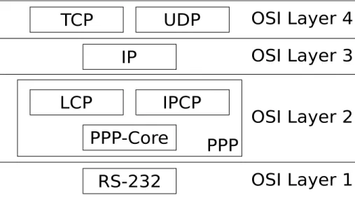
(12) C HAPTER 2 Stack Layout. 2.1 Overview In this section we aim to give the reader a brief overview of how the stack is designed.. 2.1.1. Architecture. The stack was designed to run on any platform supporting the C language with a minimum of one kilobytes of RAM. The hardware dependant code is such as timers and serial communication is separated from the core of the stack. The core of the stack should be ANSI C compliant.. 2.1.2. Layers. The stack is designed in layers, see figure 2.1, where the lowest layer is the physical layer in the form of RS-232. On top of the RS-232 is the Point-to-Point-Protocol(PPP) layer that handles encapsulation of the data on the physical link. Above that is the InternetProtocol(IP) layer that mainly handles the addressing of data. The top layer is represented as the User-Datagram-Protocol(UDP) and Transmission-Control-Protocol(TCP) layers that handles the more fine grained addressing, checksumming and in the case of TCP in-order-delivery of data. These layers represent the layers one to four of the Open-Systems-Interconncetion(OSI) reference model [4].. 2.1.3. Current Implementation. The main goal of the current implementation is not raw performance, it’s simplicity, “robustness” and modularity. Since the target is an embedded system we also tried to 3.
(13) 4. Stack Layout. Figure 2.1: Stack Layout. minimize the memory footprint as well as avoid copying of data. Generally each layer, described in figure 2.1, is encapsulated within a module. We’ve also strived to keep the coupling between the modules to a minimum.. 2.2 Discussion 2.2.1. Alternatives. Before writing this stack we evaluated a few other stacks, such as lwIP [5], uIP [6] and the microchip TCP/IP stack [7]. uIP The uIP stack is very small stack targeted for embedded systems. While it has support for both TCP, UDP and ICMP, it does not support PPP. The stack design is not modular, this is mainly because the stack was designed for high perfomance and low RAM usage. lwIP The lwIP is a larger and more powerful stack than uIP but the memory footprint is also larger. This stack has support for PPP. While this stack is very capable the memory footprint for the stack is the area of tens of kilobytes of RAM. This is simply too much for microcontrollers in the lower range that we are targetting. Microchip The Microchip TCP/IP stack is a modular stack with support for numerous protocols.
(14) 2.2. Discussion. 5. such as TCP, UDP, ICMP, HTTP, FTP, DHCP, SNMP and TFTP. This stack does not have support for PPP. The stack is also tightly coupled with the PIC18, PIC24 and dsPIC microcontroller families.. 2.2.2. Current Stack Implementaion. Since none of the alternatives gave us exactly what we wanted we decided that it would be easiest to implement a new stack to accommodate for our needs. Another reason to implement our own stack was the fact that it should be possible to run it under tinyTimber. While we could have adopted another stack and extended it we would have had to rewrite large parts of it. This would require a fundamental knowledge of the interior structure of the stack as well as the protocols involved. The resulting stack would not have any resemblance with the original stack and the advantage of using a tried and tested stack would have been lost. Given these facts we decided that it would be more feasible to implement our own stack from scratch. We also found it a lot more interesting and challenging, but that’s beside the point. The architecture that we have run the stack under is a PIC18F6622 with about four kilobytes of RAM and 64 kilobytes of flash. A simple echo-server example gave us a total RAM usage just below 1600 bytes. This also includes a 512 bytes software call stack and 256 bytes of dynamic memory. The remaining memory is used to maintain the internal state of the stack. We could have gained some bytes using various tricks and assumptions but to keep the stack modular, portable, extendable and maintainable we have tried to avoid them..
(15)
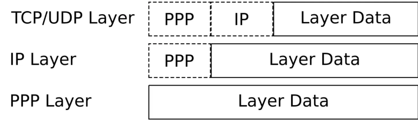
(16) C HAPTER 3 Network Buffer. This chapter describes how the network buffer structure, used throughout the stack, is designed.. 3.1 Overview The network buffer module was designed to make it easy to pass data between different layers in the stack. It is the most fundamental type within the stack and thus is fundamental to understanding how the stack works.. 3.1.1. Layers. Since the stack works in layers the network buffer was designed to make the transition between those layers easier. The network buffer is simply a buffer with an extra layer pointer. This layer pointer describes where in the buffer we are. The concept is simple. When we receive data on the link layer we are at the lowest layer and all the data is included in the layer. Once we pass the buffer to the above layer we set the layer pointer to the first byte of the next layer. Let’s see how this would work for the PPP layer. On the PPP layer we usually have a two byte protocol. When we receive the packet on the PPP layer we get the layer pointer and deal with the packet accordingly, but before we send the packet to the next layer, perhaps the IP layer, we move the layer pointer “up” two bytes. Thus allowing the IP layer to treat the layer as simply an IP packet without knowledge about the PPP layer(see figure 3.1). 7.
(17) 8. Network Buffer. Figure 3.1: Network buffer layout, the dashed areas are not visible to the current layer.. 3.1.2. Allocation. The network buffer module allows for both static and dynamic allocation of the buffer but the preferred way is dynamic. The only time we use the static allocation is when we wish to be sure that the buffer is always available. The module also allows the user to specify the functions for allocating and freeing the memory.. 3.1.3. Chaining. To make things easy the network buffer could also be used as a singly linked list(see figure 3.2). This is used extensively throughout the stack and the overhead of a single pointer is a small price to pay for not having to implement a linked list where the nodes would either have to be pre-allocated or dynamically allocated.. Figure 3.2: Network buffer list..
(18) 3.2. Discussion. 9. 3.2 Discussion 3.2.1. Overhead. The network buffer does incur some overhead but we strongly believe that the benefits outweigh the losses. The network buffer would allow us to easily replace the PPP layer with an Ethernet layer without altering the rest of the stack.. 3.2.2. Dynamic Memory. Another thing that we consider to be a benefit is that it encourages the user to use dynamic allocation of memory. This is usually supplied with the standard C library. If this is not the case then we supply our own memory allocator that is fairly portable, it’s not the fastest memory allocator out there but it works. Keep in mind that the underlaying memory allocator directly affects the performance of the Network Buffer module and will thus directly affect the perfomance of the stack..
(19)
(20) C HAPTER 4 PPP. This chapter describes the Point-To-Point-Protocol(PPP) as well as the Link-ControlProtocol(LCP), Internet-Protocol-Control-Protocol(IPCP) and PPP in HDLC-like framing(HDLC).. 4.1 Overview The PPP-protocol was created to provide a standard way of encapsulating and transporting multi-protocol datagrams over a point-to-point link. To achieve this the link itself is governed by a Link-Control-Protocol(LCP) and each of the network protocols are governed by their own Network-Control-Protocol(NCP). The LCP first negotiates the link and once the link is up the NCP protocols can start their negotiation. The PPP layer corresponds to layer two in the OSI Basic Reference Model [4].. 4.2 Specification 4.2.1. PPP. The PPP protocol is specified by RFC1661 [1]. The PPP specification covers the phases of the link, the option negotiation automaton and the LCP protocol.. 4.2.2. IPCP. The IPCP protocol is specified by RFC1332 [8]. The IPCP specification describes the NCP for the IP protocol. The options negotiation is based on the one described in [1]. 11.
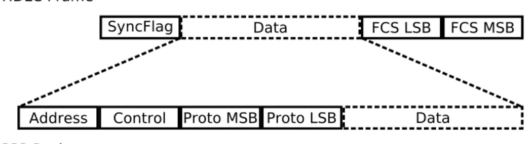
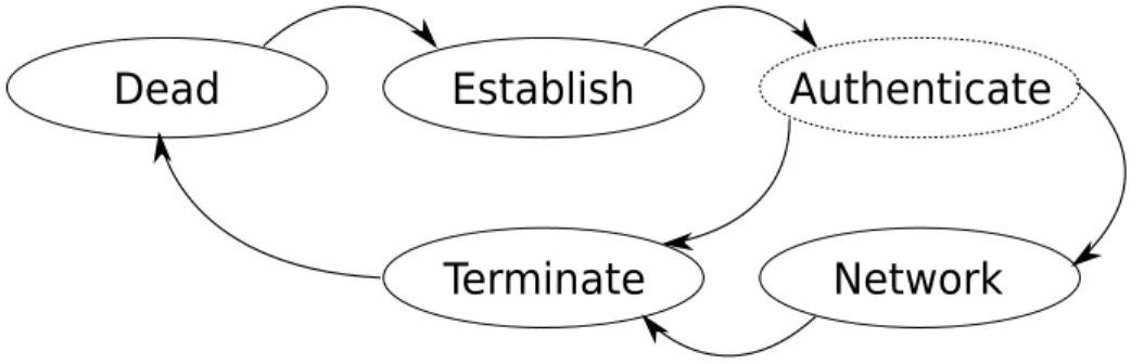
(21) 12. 4.2.3. PPP. HDLC. The HDLC protocol is specified by RFC1662 [9]. The HDLC specification covers how PPP packets should be encapsulated on a serial line in a HDLC-like manner. It also adds negotiation options for the LCP that are not specified in [1].. 4.3 Implementation 4.3.1. PPP. Before we go into the details of how the different parts are implemented we must look at the basic layout of a packet. The figure 4.1 shows the basic packet layout of a HDLC frame and a PPP packet. Each HDLC frame starts with a sync flag and followed by the PPP packet. The last two bytes are the Frame-Check-Sequence(FCS) and is used to determine if the data was corrupted when sent over the link. To make life easier the implementation usually sends a SyncFlag after each packet as well so that we can determine when the entire packet has arrived, without having to wait for the next packet. Each PPP packet starts with an address byte and a control byte, these bytes are usually static for a point-to-point link but are required by default. Next is a two byte protocol field. Some of these fields can be discarded or compressed if the implementation is capable of this. For more information see the LCP section below.. Figure 4.1: Packet Layout. 4.3.1.1 Link The PPP specification describes five different phases for the link, Dead, Establish, Authenticate, Network and Terminate. The current implementation supports all phases except Authentication. The authentication phase should only be used if requested dur-.
(22) 4.3. Implementation. 13. ing the Establish phase. Authentication is not mandatory and not supported by the current implementation. See figure 4.2 for the layout of the phases/states.. Figure 4.2: PPP state/phases, dashed states non-existant in the current implementation.. The following is a brief description of the link states/phases. Dead. PPP is in the Dead state upon initialization, from this state we always go to the Establish state. Establish. When we enter the Establish state we will start negotiating the link with the LCP protocol. In this state we may be asked to enter the Authenticate state but as stated earlier this is not supported by the PPP module. When PPP is in this state all packets designated to protocols other than LCP are dropped. Upon successful negotiation of the link we will enter the Network state. Authenticate. When authentication is requested during the Establish phase we will enter this state. Upon successful authentication the link will enter the Network state, upon failure the link will be terminated. As mentioned earlier this is not supported by the current implementation and only mentioned here for completeness. Network. When PPP enters this state all NCP protocols are allowed to start their negotiation. We can either enter the Terminate state or the Establish from this state. The Establish state is usually entered when the peer wishes to renegotiate the link and The Terminate state is entered when request by the peer, the program or upon an unrecoverable error. Terminate. When PPP is asked to terminate the link, either by LCP or because of some other.
(23) 14. PPP error, we will enter the terminate state. All packets designated for protocols other than LCP will be dropped.. 4.3.1.2 LCP The LCP protocol is used during the Establish phase to negotiate the link capabilities. The specification for PPP [1] defines the negotiation automaton that should be used during the link negotiation. This automaton is subsequently used in all other NCP protocols. For details about the states of the automaton see [1]. The format of the configure options are also defined in [1] and all other NCP use the same format for the options. The following options are supported in the current implementation. MRU. The Maximum-Receive-Unit decides how many bytes can be received. The default value for this option is 1500. This is a bit too much for an embedded system so we found that it was vital to implement this option. ACFC. The Address-and-Control-Field-Compression allows PPP to omit the address and the control field bytes when sending a packet. These bytes always have a static value in a point-to-point link and thus they are redundant. The gain is only two bytes per packet but the implementation is trivial. PFC. The Protocol-Field-Compression is used to compress the protocol field in the PPP packets. The gain is only one byte per packet when protocol is < 256 but the implementation is trivial. ACCM. The Async-and-Control-Character-Map originates from the HDLC [9] protocol. It allows the peer to define which control characters must be escaped. If a character is marked to be escaped in the ACCM then it will be dropped if it arrives without being escaped.. 4.3.2. IPCP. The IPCP module is the NCP for IP datagrams. This protocol must be up before any IP datagrams can be sent or received. The following options are supported in the current implementation. Address. This option is used to request a local address or notify the remote peer of the local.
(24) 4.4. Discussion. 15. address. In the current implementation we try to request the local address or if that fails we fall back on a default address. The IPCP protocol specifies two other options, the legacy Addresses option and the Compression option. For a discussion of why we did not implement these options see 4.4.. 4.3.3. HDLC. The HDLC module is the protocol used on the serial line to transmit the PPP packets. For a brief overview of how a hdlc packet might be framed see figure 4.1. The only option defined in [9] is ACCM, for a description of this option see the LCP section in 4.3.1.. 4.4 Discussion 4.4.1. PPP. As stated in 4.3.1 we do not support authentication in our PPP module. If we were to support this we would have to do some very extensive testing to make sure that it is really “safe” and that there are no leaks of private information, otherwise the authentication would only provide a false sense of security. There are two more options specified in [1] that are not implemented. The first, QualityProtocol, is used to determine when link is dropping data. Since the current implementation uses a serial line(RS-232) the link itself will not drop any data. We might still run out of buffer space but that will be noticed and logged by the higher level protcols. Logging this on the lower level as well would only waste resources. The Magic-Number is used to determine whether a link is loop-backed that is when we send a packet we get the same packet back. It is quite possible to get a loop-backed serial device but those cases are quite rare so we chose not to implement the option.. 4.4.2. IPCP. The specification for IPCP [8] defines two additional options beside the one that we have implemented, the first being Addresses. The Addresses options is a legacy option and it’s use is discouraged. Since we are unlikely to use legacy hardware with this implementation we chose not to implement this option. The second option is compression. While compression is really a good thing for embedded systems it also introduces a lot of complex logic. There are basically two ways of implementing the compression, either the IP-layer(Chapter 5) knows what compression is or it’s blissfully ignorant. In the case where the IP-layer is blissfully ignorant of the compression we would have to build a new IP header in the IPCP-layer before sending.
(25) 16. PPP. the packet to the IP-layer. The only gain we would see from this is more bandwidth for our data. If we instead implemented the IP-layer with knowledge of the compression we would be able to gain both bandwidth and space, this however would introduce a lot of logic into the IP-layer and possibly the TCP-layer(Chapter 6). This does not help the “robustness” of the stack and thus we decided not to implement this. It is however quite possible, although not trivial, to extend the stack with this functionality should it be necessary.. 4.4.3. HDLC. The only thing worth mentioning about HDLC is that the remote peer MRU is not honored, it is left to the user to make sure that the packet is not too large for the remote peer. This is usually done with the maximum segment size option for TCP(Chapter 6)..
(26) C HAPTER 5 IP. This chapter describes the Internet Protocol(IP).. 5.1 Overview The Internet protocol is designed for use in interconnected systems of packet-switched computer communication networks. The protocol provides a way to transmit blocks of data, called datagrams or packets, between hosts on the network. The IP layer corresponds to layer three in the OSI Basic Reference Model [4].. 5.2 Specification The Specification[2] states that all host must be able to receive and handle datagrams of at least 576 bytes. Packets traveling over so called “small packet” networks may be split into multiple packets called fragments. Each fragment must contain at least eight bytes of data and all implementations should be able to reassemble fragments to form a whole datagram again. The Protocol header may also contain optional information. Such as how the packet is supposed to be routed through the network, or to record which route a particular datagram has traveled to reach its destination. IP is a so-called “best-effort” protocol. It does not guarantee that a transmitted packet actually arrives at the destination, nor that transmitted datagrams arrives in the order they we’re sent.. 5.3 Implementation The implemented IP module is completely stateless and holds no notion of time. All packets going through the module is processed in an appropriate way and sent on it’s 17.
(27) 18. IP. way. As soon as the packet leaves the module it is forgotten. The sending of packets are even more straightforward. Most header values are set to a default value. Only the crucial parameters, such as where the packet is destined and where it came from are dynamically set. No options are ever used and the header size is always the smallest possible. The implemented module sidesteps the specification on one major point. It does not reassemble fragmented IP-packets. If a datagram is a fragment the packet is discarded with no further notice. Another thing to note is how the module handles IP-packets with header options. It accepts them, but it does not parse them.. 5.4 Discussion The choice not to implement fragmentation was made because we wanted to keep the module as simple as possible. Another issue was the hard memory restrictions when working in embedded environments. To assemble fragments we would need to buffer them at the IP layer until all fragments has been received. We have no way of knowing if the datagram is useful or not. So we might end up using memory for useless data while dropping important packets. Since the TCP(see chapter 6) provides us with an option to control the size of received IP datagrams we can avoid fragmentation by not allowing the remote side to send packets that would be fragmented. Options parsing were left out of the current implementation, simply because we did not see the point in creating more complex code just to gather routing data. If this stack was supposed to be used in routers or some other non-end host the choice would of course be different..
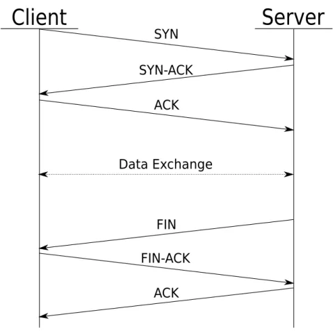
(28) C HAPTER 6 TCP. This chapter covers the Transmission Control Protocol(TCP [3]).. 6.1 Overview The TCP protocol provides applications with a reliable way to transfer data over a network. It guarantees that the data is delivered to the remote peer and that the data is delivered to the application in the correct order. The TCP protocol is a connection oriented protocol. This means that a connection only supports data exchange between two hosts. The TCP layer corresponds to layer four in the OSI Basic Reference Model [4].. 6.2 Specification The TCP protocol is intended to provide a reliable process to process communication over a packet-switched network. The protocol guarantees that sent packets are delivered in the correct order to the remote process. This is achieved by assigning a sequence number to each data byte and providing a mechanism to report which bytes have been received. All TCP connection must be set up before the sending of data can begin. This setup is called the “three-way-handshake” which basically means that the two hosts exchange information about capabilities and which number the first byte transmitted in each direction will have. During the data transfer each side of the session acknowledge the amount of data it has received. If no acknowledgement is received after a certain amount of time a retransmisson is issued. The suggested algorithm for determining the time between sending the data and issuing a retransmisson is a function of the round trip time(RTT). The RTT is 19.
(29) 20. TCP. defined as the time between sending data and receiving an acknowledgement. The TCP specification also provides a way to control the flow of data. For each packet the TCP sends, it provides its current window size. The window indicates how many bytes of data the TCP is prepared to accept. The sending TCP should not create packets larger than the receivers window size, but it is not required to repackage packets already in the send queue. The protocol also provides is a way to communicate urgent data. The presence of urgent data should be reported to the application program so that it may take action to process the urgent data as soon as possible. When the data exchange is done the connection is closed by exchanging special closing packets. After this, it is required that the TCP is quiet for some time to let any packets still traversing the network expire. This feature is to make sure that data belonging to old sessions is not mistaken for data destined to new sessions. For a typical TCP session see figure 6.1.. Figure 6.1: Typical TCP session. Client initiates the session, data is exchanged and the sessions is closed by the server..
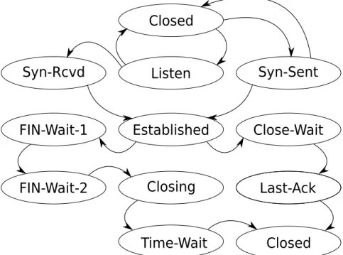
(30) 6.3. Implementation. 21. 6.3 Implementation 6.3.1. State Machine. The TCP state machine handles state transitions for a connection. The suggested state machine for a TCP connection can be seen in figure 6.2. The currently implemented state machine has merged a few states as seen in figure 6.3. The reason for merging these states is to reduce the code size and increase the maintainability of the code. The implemented state machine sidesteps the implementation on one major point. A connection is supposed to end up in a silent state after it has been torn down. This implementation does not honor this, the connection is cleaned up at once and may be reused instantly.. Figure 6.2: Original TCP state machine.. 6.3.2. Packet Handler. The packet handler handles incoming and outgoing TCP packets. Both outgoing and incoming buffers are held and managed in singly linked lists..
(31) 22. TCP. Figure 6.3: Merged TCP state machine, the dashed states are non-existant in the current implementation.. 6.3.2.1 Sending Packets Outgoing packets are created when a process wants to send data to the remote side. For each send call the TCP module will immediately send the packet and insert it into the retransmission queue. A thing to note about this scheme is that the caller is responsible for the utilization of bandwidth. The TCP in itself does not buffer outgoing data and determines when there is enough data to be transmitted. When buffers are larger than the remote window size it does not split the data across several packets but instead notifies the user of the transgression. The buffer the user supplies is prepended with the appropriate header and sent onto the network. Outgoing packets are removed from the send queue when the whole packet has been acknowledged by the other side.. 6.3.3. Receiving Packets. Incoming packets are examined to determine if any new data is contained within the packet. Upon deciding that there is new data in the packet the module copies the data to another buffer that only contains the user data and a small amount of control information. This buffer is then inserted into the users receive queue. This means that the packet is saved and delivered to the user the way they arrive. The specification says that the TCP is supposed to notify the user if urgent data is available. This implementation does not do this. Any urgent data is transparent to.
(32) 6.4. Discussion. 23. ordinary data.. 6.3.4. Retransmission Timer. The current implementation has a single timer for each connection that determines when a retransmission should be issued. Since there is only timer and there might be multiple packets in the queue at the same time. The timer cannot keep track of when the individual packets should be retransmitted. Instead it uses the notion of progress. Progress is defined as receiving acknowledgment that it has received new data. Whenever no progress has been made for a specific time, a retransmission is issued and the first packet in the send queue is sent.. 6.4 Discussion 6.4.1. State Machine. As noted above we do not follow the specification by keeping silent after a connection has been terminated. This choice was made simply due to resource considerations. We did not want to lock a connection resource while waiting for the connection to time out. This is especially dire if the stack is compiled only to have one connection. We would end up unable to create a new socket, even a socket on a different port. This would mean that we would loose our access to the network every time we close a connection. In the current implementation the user is responsible for keeping silent on the port, one could argue that a scheme should be developed to handle this situation without locking the structure. But this would require overhead in the form of control and timer data as well as increased complexity of the code. The design to merge states ends up in somewhat slower code due to the fact that the state must be checked when deciding which action to take. This is weighted up by the fact that it simplified the development a great deal, as the code only needed to be changed in one place in case of a bug or other adjustment. Should the need for speed arise, the breakup into separate states should be easy.. 6.4.2. Packet Handler. The absence of the urgent data notification to the user is the other major point on which we sidestep the specification. The choice to skip urgent data notification was made in order to keep the implementation as simple as possible. The introduction of urgent data would require the handler to repackage the data and keeping track of it’s importance. Since the target systems usually have a limited amount of memory, the user cannot let the receive queue fill to any significant amount. This means that the user probably reads the urgent data within a short time anyway..
(33) 24. TCP. The current implementation exposes the internal packet based handling of the stream. It assume that the user is aware of the overhead of sending data. The worst case scenario is when the user sends one byte at a time. Generating an approximate overhead of 40(IP + TCP header) control bytes for each data byte. This imposes some considerations to be made when designing the application. On the other hand the implementation avoids expensive copying of data for buffering and greatly simplifies the implementation. At the same time this design gives the user control of the data-flow.. 6.4.3. Retransmission Timer. The specification suggest that the retransmission timeout value is dynamically calculated using the RTT. This is not done in the current implementation. The reason for this is simplicity and resource considerations. The RTT calculation requires at least a timestamp for each packet, to be able to use the calculated we would also require a timer for each packet. A dynamic retransmission timeout might allow for a higher bandwidth utilization, but performance was not a primary consideration..
(34) C HAPTER 7 UDP. This chapter describes the User Datagram Protocol(UDP)[10].. 7.1 Overview The UDP protocol provides application programs with the mechanism to send datagrams to other applications on the network with a minimum of protocol overhead. No guarantee is made that data is delivered to the remote peer nor that it arrives in the correct order. The UDP layer corresponds to layer four in the OSI Basic Reference Model [4].. 7.2 Specification The UDP protocol is designed to be used with the IP-protocol as the underlying protocol. The IP protocol(chapter 5) provides a way of sending datagrams between hosts on a network. The UDP protocol takes this one step further and provides a way to send packets to a specific application running on a host. As with the IP-protocol UDP does not provide any guarantee that packets are delivered nor that they arrive in the correct order. The UDP header contains a checksum field but the calculation is optional. The absence of checksum calculation is signaled by setting the checksum field to zero.. 7.3 Implementation The implemented UDP module is very simple in it’s behavior. Sending datagrams is done by prepending the user buffer with an minimum UDP header and sending the datagram to the IP module. There is a compile time option not to calculate a packets checksum when sending. Incoming packets are first validated. If the checksum field is zero the 25.
(35) 26. UDP. datagram is assumed to be correct. Upon deciding that the datagram is destined to some open connection the data is copied into a smaller buffer with some minor control data that specifies where the data originated from. These data buffers are held in a linked list until the user requests it. One thing to note about the handling of incoming packets is that when the receive queue is full, all incoming packets are dropped. This means that old data can be stored in the receive queue indefinitely.. 7.4 Discussion There is not much to say about the UDP module. It is a simple top-down implementation and it is the least tested module in the stack. The habit of dropping new datagrams when the receive queue is full is the choice of simplicity. By storing the newest datagram and thrashing the old would only introduce additional complexity. There is no way for the UDP module to decide which data is important anyway..
(36) C HAPTER 8 tinyTimber. 8.1 Overview Part of our project has been to implement a tinyTimber runtime system for the PIC18 microcontroller as well as developing a tinyTimber interface to the stack. The interface has only been tested on the POSIX([11]) version of tinyTimber.. 8.2 tinyTimber Before we discuss how the stack interface for tinyTimber was designed, we will give you a brief introduction to tinyTimber. tinyTimber is a lightweight run-time kernel for embedded systems. tinyTimber is based on the notion of reactive objects. A reactive object is a component that reacts to incoming events by updating its internal state and might emit events of its own. This maps nicely to today’s interrupt generating hardware. As an example the RS-232 driver might be modeled as a reactive object where the receive/send interrupts are the events that trigger an internal state change. The driver might propagate received data as an event to another object, for example a display driver or in our case the HDLC object. In tinyTimber each object should be viewed as executing in parallel to other objects. To facillitate state integrity tinyTimber must guarantee mutual exclusion to each object. To achieve this each method call that crosses an object boundary must pass through the run-time kernel. Most embedded systems only have a single processor, thus tinyTimber must somehow emulate a parallel behaviour. tinyTimber must also be able to determine which event 27.
(37) 28. tinyTimber. should be processed first. This is done in an Earliest-Deadline-First (EDF) fashion. Unlike most systems tinyTimber does not use priorities. Instead each event has a baseline and deadline which defines the time-frame in which it must be executed and completed. For more information about tinyTimber see [12].. 8.3 PIC18 The only thing we really needed to do to port tinyTimber to the PIC18 was to write a timer and a simple task-switching interface. While this was a simple task some architecture related issues where encountered as described in the discussion(8.5.1).. 8.4 Stack Interface The tinyTimber interface is implemented as simple wrapper objects around each of the modules with a minimal interface. The exception is the PPP module that was split up into several sub-objects to allow per-protocol events. The TCP and UDP layers introduce a special socket object to allow us to perform user notification. The interface is merely an abstraction and does not change the inner workings of the stack in any significant way. One thing we where forced to implement for tinyTimber is the ability to cancel messages. This was not in the original tinyTimber code but was really necessary to get a well defined timer cancellation behavioir.. 8.5 Discussion The original plans for the stack was to actually run it under tinyTimber on the PIC18 microprocessor. While this is still possible to do it would have required a lot testing and tuning to account for the memory constraints. We highly doubt that the stack itself would gain anything from the real-time scheduling capabilities that tinyTimber offers. The application running on top of the stack however, might benefit from it.. 8.5.1. tinyTimber and PIC18. The greatest obstacle to overcome when working with the PIC18 microprocessor was the internal call-stack. This works very well for single-threaded programs but when you implement threads this really gets in the way. The only way to obtain the call-stack entries is to pop them off the stack one by one. This is not only costly in cycles but also in memory. It also makes it hard to predict the time it would take to perform a task-switch unless we assume the worst case(which clearly introduces overhead). Due to.
(38) 8.5. Discussion. 29. this restriction the programmer would have to be very careful when writing the code to minimize the impact of the task-switching. The segmented memory also forces you to modify the code of the tinyTimber core. It is worth noting that the overhead comes from the multi-threaded nature of the current implementation of tinyTimber for PIC18. Any multi-threaded system would suffer the same overhead on the PIC18 architecture. Final Verdict The final verdict for tinyTimber on the PIC18 architecture is still open for discussion but we recommend that you think twice before you use the two together. Using tinyTimber will not always make the project easier unless you are in dire need of real-time scheduling. In this case tinyTimber might help you but you will still need a detailed knowledge of the PIC18 architecture..
(39)
(40) C HAPTER 9 Conclusion. In this report we have presented our current stack design and implemention. We have discussed the issues and overhead of running a truly modular stack on a small embedded system with a limited amount of RAM. The main features of the stack are: • Support for PPP • Support for IP, TCP and UDP • Portable • Modular design • RAM footprint below two kilobytes • tinyTimber interface. 31.
(41)
(42) R EFERENCES [1] W. Simpson, “The Point-to-Point Protocol (PPP).” RFC 1661 (Standard), July 1994. Updated by RFC 2153. [2] J. Postel, “Internet Protocol.” RFC 791 (Standard), Sept. 1981. Updated by RFC 1349. [3] J. Postel, “Transmission Control Protocol.” RFC 793 (Standard), Sept. 1981. Updated by RFC 3168. [4] “Information Technology - Open Systems Interconnection - Basic Reference Model: The Basic Model.” ISO/IEC 7498-1:1994 (Standard), Nov. 1994. [5] A. Dunkels, “lwIP http://www.sics.se/˜adam/lwip/.. A. [6] A. Dunkels, “uIP - A TCP/IP http://www.sics.se/˜adam/uip/.. Lightweight stack. for. TCP/IP 8-bit. stack.”. microcontrollers.”. [7] Microchip, “Microhip TCP/IP Stack.” http://www.microchip.com/tcpip/. [8] G. McGregor, “The PPP Internet Protocol Control Protocol (IPCP).” RFC 1332 (Proposed Standard), May 1992. Updated by RFC 3241. [9] W. Simpson, “PPP in HDLC-like Framing.” RFC 1662 (Standard), July 1994. [10] J. Postel, “User Datagram Protocol.” RFC 768 (Standard), Aug. 1980. [11] IEEE and The Open Group, “POSIX.” http://posixcertified.ieee.org/. [12] Lindgren, P. Nordlander, J. Kero, M. Eriksson, J., “Robust Real-Time Applications in Timber,” in Electro/information Technology, 2006 IEEE International Conference on, pp. 191–196, May 2006.. 33.
(43)
Figure
+4

Related documents
Pars enim Calculi Variationis practica in om nibus, qui nobis sunt n o ti, libris elementa hujus disciplinæ tra ctantibus, omni cura atque diligentia explicata
Cum vero quod reliquum eft, Divinæ voluntati etiam non penitus perfpeftae acquiescere noluerint, fed rationis fpeculativæ op e mortales fibi explicare præ-
Q uod fi plurimi in tenebris Gentilismi palpitantes, ad abfonas quas vis imo & horrendas de mediis expiationis, prolapfi eafent opiniones, non ta m en prorfus
nixum, principium fiendi Jegis naturalis. Ergo ever titur tam principium efiendi , quam fiendi eiusdem ; ergo nulli a&ionum,ad eam dari poteft relatio : Er g o
Medvetenhet om att valt företag samt valda influencers inte kan tala för hela branschen finns, men företaget är valt eftersom de varit en av de första med att arbeta med
A company with mainly Swedish employees founded in a Swedish organizational culture, the Volvo Way, together with the cultural efforts at Volvo IT, but with
simma trots att de enligt skolsystemet på Nya Zeeland ska kunna det (Moran 2008, s.117). I kursplanens centrala innehåll står det uttryckt att simning, lekar i vatten samt
The comparison of means was performed between groundwater samples and water leachates from nearby sampling points, between the Eurofins results and the total concentrations for the
