Effects of Austempering Process
on Mechanical Behavior Properties
of Compacted Graphite Iron
PAPER WITHIN Materials and Manufacturing Department AUTHOR: Inamul Hassan
TUTOR:Rohollah Ghasemi JÖNKÖPING February 2019
Postadress: Besöksadress: Telefon:
engineering. The work is a part of the Master of Science programme. The authors take full responsibility for opinions, conclusions and findings presented.
Examiner: Mohammed Reza Zamani Supervisor: Rohollah Ghasemi
Scope: 30 credits (second cycle) Date: August 2019
Abstract
The thesis paper here focuses on the effects of the austempering temperature (TA) and the austempering time (tA) on the unalloyed fully ferrite Compacted
Graphite Iron (CGI), to obtain improve in mechanical properties and the study of the microstructure. The unalloyed CGI samples were austenitised at 850oC
for 60 and 90 min and were then heat treated at 275, 325 and 375oC with
different holding times at 30,60,90, and 120 mins. Mechanical properties like the tensile strength, yield strength, young’s modulus, Brinell and Vickers harness were conducted to perform the analysis on the samples. LOM was used for the study of the microstructure and SEM was used for the study of fractography of the fractured tensile bar.
Summary
Heat treatment is the process used to achieve desired mechanical properties. For a long period of time heat treatment process is been used for the ductile iron (DI) to obtain Austempered Ductile Iron (ADI), which significantly shows good mechanical properties but lacks behind in the thermal conductivity. The disadvantage of DI has led the manufactures in choosing Compacted Graphite Iron (CGI), which significantly has better thermal conductivity. CGI has significantly lower mechanical properties when compared to DI. The thesis work performed focuses on heat treatment of the CGI, and how Austermpering process influence the microstructure and the mechanical properties of the CGI samples.
The specimen for the tensile test were made from the piston ring and later they were heat treated to achieve the desired mechanical properties. The heat treatment was conducted by maintain 850oC as the austenitising temperature
for different holding time 60 and 90 mins. And the austempering was followed by 275,325, and 375oC for different holding time for 30,60,90, and 120 mins.
Tensile test, Brinell and Vickers hardness, microstructure analysis and fractography analysis was performed onto the Austempered CGI samples. During the analysis of the austempered CGI, it has been noticed that the heat treatment process has shown improved mechanical properties and has also influenced the microstructure of the CGI. A mixture of retained austenite and acicular ferrite were formed in the austempered CGI. The results have shown that lower austempering temperature samples have substantially gained more tensile strength and hardness.
Keywords
Austempered CGI, austenitising, retained austenite, acicular ferrite, lower austempering temperature, higher austempering temperature, mechanical properties.
1 Introduction ... 5
1.1 BACKGROUND ... 5
1.2 PURPOSE AND RESEARCH QUESTION ... 6
1.2.1 Purpose ... 6 1.2.2 Research Questions ... 6 1.3 DELIMITATION ... 6 1.4 OUTLINE ... 6
2 Theoretical background ... 7
2.1 CAST IRON ... 72.2 TYPES OF CAST IRON ... 8
2.2.1 Grey flake Cast Iron (GCI) ... 9
2.2.2 Spheroidal Graphite Iron (SGI) ... 9
2.2.3 Compacted Graphite Iron (CGI) ... 10
2.3 MATRIX STRUCTURE AND THEIR CHARACTERISTICS ... 11
2.3.1 Austenite ... 11 2.3.2 Ferrite ... 11 2.3.3 Pearlite ... 11 2.3.4 Martensite ... 12 2.3.5 Ausferrite ... 12 2.4 HEAT TREATMENT ... 13 2.4.1 Effects of Austenitization – ... 13
2.4.2 Effects of Austermpering on Iron... 14
3 Method and implementation ... 16
3.1.1 Sample preparation – ... 16
3.1.2 Microstructure evaluation – ... 16
3.1.3 Hardness – ... 16
3.1.4 Heat treatment – ... 17
3.1.5 Tensile test – ... 17
4 Findings and analysis ... 18
4.1 MICROSTRUCTURE – ... 18
4.2 INFLUENCE OF THE AUSTENITIZING TEMPERATURE AND TIME ON THE MECHANICAL PROPERTIES. ... 22
4.3 FRACTURE SURFACE ANALYSIS ... 28
5.1 DISCUSSION OF METHOD ... 31
5.2 DISCUSSION OF FINDINGS ... 31
5.3 CONCLUSIONS ... 32
6 References ... 33
1
Introduction
1.1 Background
In the world where the industries are aiming in reducing the weight and increase the power input of the material. Grey Cast Iron (GCI), which is extensively used in heavy duty diesel engines, plays a vital role in wear resistance components like the cylinder liners, piston ring, etc. Though it has good wear properties, it lacks in the mechanical properties when compared with the other grades of cast irons, such as Spheroidal Graphite iron (SGI) or Ductile Iron (DI) and Compacted Graphite Iron (CGI). The difference in GCI, SGI and CGI, mainly lies in the graphite matrix distribution. Compared to GCI, the other two grades of cast iron possess good mechanical properties, and this is due to the presence of graphite flakes found in the GCI, which infuriate to cracks when stress is applied to the material. Due to its limitations, the study for SGI and CGI has been increased, especially the study of SGI, due to its nodular graphite present in the structure, which makes it better in mechanical properties when compared to GCI. Attempts on making SGI stronger by heat treatment and thus Austempered Ductile iron (ADI) was created which possess excellent mechanical properties such as high strength and hardness, coupled with substantial ductility, toughness, good wear resistance, and good fatigue properties, which replaced enormous GCI components. But the SGI has its own disadvantages when comes to thermal conductivity, which limits its application in the internal combustion chamber like piston rings, cylinder heads etc. . In recent years, the use of CGI has increased with improved mechanical properties compared to GCI and good thermal properties when compared to SGI. CGI has good tribological properties and hence they have been used more in the different automotive components and other industrial applications. Several research and attempts have been made in making of the ADI, but due to its poor thermal conductivity, there is lack of usage in the internal combustion engine for the tribological components. A very limited data is available on the heat treatment of the CGI, which has provoked this thesis on working on Austempered CGI. This master thesis is done at Jonkoping University to examine the influence of austempering on conventional CGI by heat treatment process at different austempering time and temperature, and to analyze the influence of Austempered CGI on the mechanical properties
1.2 Purpose and research question
1.2.1 Purpose
The main objective of this thesis is to analyze the mechanical properties of convential pearlitic CGI through different salt-bath austempering heat treatment technique. In addition, correlating the microstructure analysis and the fractography analysis with the mechanical improvements of the material.
1.2.2 Research Questions
1. How does both the austempering process and the austenitising process with time and temperature, affects the microstructure of conventional CGI?
2. How does the heat treatment affect the mechanical properties of the material with respect to time and temperature?
1.3 Delimitation
In this complete thesis it is focused on the mechanical behavior and not the tribological behavior.
1.4 Outline
The report starts with some background of the base material. In starting of the background, some basic information with the classification of the cast iron is provided. In later part of the background, there is some information about the heat treatment. After the theoretical background, methodology is been written, where all the different tests and methods which has been used while performing the thesis has been explained. Lastly results and analysis of the tests has been provided.
2
Theoretical background
There has been a lot of research on the SGI when compared to the CGI. The reason behind it is that SGI has more applications in the industry than CGI due to its mechanical properties. But the SGI lacks behind in the tribological applications in the internal combustion engines, due to its thermal conductivity more research has been carried out on CGI. But CGI lacks behind in mechanical properties when compared to SGI. To get a stronger material with good mechanical properties, and tribological properties, CGI has to be heat treated. As the focus of this thesis is to examine the effect of heat treatment on CGI to achieve better mechanical properties. To obtain a strengthen material austempered heat treatment is carried out and later results were analyzed, to examine the impact of heat-treatment on the microstructure and mechanical properties of austempered CGI. In this theoretical background, research-based ADI is used as reference to get the results for the Austempered CGI.
2.1 Cast Iron
Cast iron is basically the alloy of iron, carbon and some other elements such as phosphorus, silicon, etc. The cast iron is based on the iron -carbon equilibrium diagram as shown in the Figure 1 Iron-carbon Equilibrium diagram. According to I Charkrabarty, the Iron-Carbon melt solidification confide in the factors like graphitization potential, inoculation treatment, and the cooling rate, to either obtain stable Fe-Graphite system or metastable Fe-Fe3C system
[1]. From the iron-carbon equilibrium diagram, it is observed that over 2 % of carbon in the iron melt belongs to carbon. The other elements in total constitutes about 10% with carbon as the primary alloying element which itself constitutes about 2-4%, depending on the application [2]. The properties and the microstructure of cast iron differs from that of steel. The eutectic solidification of cast iron takes place either as the stable graphite phase or the metastable cementite phase. The stability of the phases depends on the nature and the treatment they are provided during solidification. Silicon increases the graphitization potential strongly in the cast iron [3]. The eutectic reaction is the austenite, and it forms different matrix during solidification, which depends on the alloying addition and the cooling rate. The solidification of the cast iron can
either form grey, white or mottled cast iron. However, for commercial irons, most of them are proceeded by the carbon equivalent value (CE) while using the iron-carbon diagram. The CE [4] is presented as
Eq 1
CE = %C+0.33(%Si+%P)-0.027(%Mn)
The presence of elements notably silicon and phosphorus determine the solubility of carbon in the molten metal [5]. However, silicon provides more toughness to the material.
Figure 1 Iron-carbon Equilibrium diagram. [3]
2.2 Types of cast iron
The Cast Irons is divided in two main group, General purpose Cast Iron, which is used in any engineering application and the other is Special purpose cast iron. The general-purpose cast iron is the main concern in this project, and it is sub divided into 3 types- GCI, CGI, and SGI. All these cast irons differentiate in their graphite morphology.
2.2.1 Grey flake Cast Iron (GCI)
The GCI is the most used in the engineering purpose applications, as it is relatively inexpensive and easy to produce. They are mostly used in the sliding wear applications, due to its high thermal conductivity, ability to withstand thermal shocks, and low modulus of elasticity. The properties of flake iron depend on the graphite flakes and the matrix structure. They usually have ferritic matrix and mostly used for non-critical components such as brake drums and clutch plates, cylindrical blocks, piston rings, etc. Higher grade grades of GCI can be achieved by heat treatment and it forms pearlitic matrix. The achievement of the pearlitic matrix depends on the alloying elements. The main disadvantage of GCI lies in the mechanical properties on cooling rate which makes them section sensitive. The cooling rate can be related for section thickness only for simple casting [6]. The increase in cooling rate will refine both the graphite size and matrix, which in return results in increased strength and hardness [7]. As per ASMI Specialty Handbook Cast irons, the chemical composition for typical unalloyed common GCI is as given in the Table 1 [7]
%C %Si %Mn %P %S
2.5-4.0 1.0-3.0 0.2-1.0 0.002-1.0 0.02-0.25
Table 1 Range of compositions of typical unalloyed GCI.
2.2.2 Spheroidal Graphite Iron (SGI)
The SGI or DI, overcomes the disadvantage of the GCI. However, it is inferior to GCI with respect to physical properties such as thermal conductivity. They form nodular shape graphite, which make them more ductile compare to GCI, hence they are named as Ductile iron (DI). They are used in most of the automotive applications such as pistons, gears, etc. The matrix obtained on solidification latter ranges from fully ferritic to pearlitic or bainitic depends on the type of cast. To obtain spheroidal graphite, either Mg or Ce is added to the chemical composition. The Mg is added in several forms including metals like Ni-Mg, Ni-Si-Mg alloy etc. [8]. Over 0.03 % of Mg is used to obtain spheroidal graphite on cast iron. There are different ways of adding Mg, as it depends on the application. Excess level of Mg results in dross formation. There are several formulae available for calculating mg, for instance [6]
𝑀𝑔 =
3
4(𝑖𝑛𝑖𝑡𝑖𝑎𝑙 S 𝑐𝑜𝑛𝑡𝑒𝑛𝑡) + 𝑟𝑒𝑠𝑖𝑑𝑢𝑎𝑙 Mg (0.03−0.05%)
𝑒𝑥𝑝𝑒𝑐𝑡𝑒𝑑 Mg 𝑟𝑒𝑐𝑜𝑣𝑒𝑟𝑦
The manufacturer’s motive is to manufacture a fine and uniform distribution of perfectly shaped spheroidal graphite in the product, which in result promotes good mechanical properties [6]. When the cooling rate changes, same effects are occurred as discussed in the GCI, but the section sensitivity of SGI is lower [7]. As per ASMI Specialty Handbook Cast irons, the chemical composition for typical unalloyed common SGI is as given in the Table 2 [7].
%C %Si %Mn %P %S
3.0-4.0 1.8-2.8 0.1-1.0 0.01-0.1 0.01-0.03
Table 2 Range of composition for typical unalloyed SGI.
2.2.3 Compacted Graphite Iron (CGI)
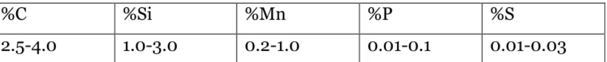
CGI or the Vermicular iron, is the iron which lies between the GCI and SGI. It has specific applications as it is used to fill the mechanical and physical properties void between the GCI and SGI. The CGI exhibits superior tensile strength, stiffness and ductility, fatigue life, impact resistance and elevated temperature properties compared to GCI [3]. It has greater resistance to cracks compared to GCI and better resistance to distortion with good elevated thermal properties when compared to SGI [3]. Due to its extensive properties, it is used in internal combustion applications such as piston rings, cylinder heads, exhaust manifolds, etc. When the molten metal solidifies, it forms a pearlitic matrix. To obtain the CGI, same Mg is added, but in this case only 0.01-0.03% of Mg is added. Excess of Mg will change the grade of iron to SGI. The cooling rate of the CGI is less section sensitive than the GCI [7]. As per ASMI Specialty Handbook Cast irons, the chemical composition for typical unalloyed common CGI is as given in the [7].
%C %Si %Mn %P %S
2.5-4.0 1.0-3.0 0.2-1.0 0.01-0.1 0.01-0.03
Table 3 Range of composition for typical unalloyed CGI
2.3 Matrix structure and their characteristics
2.3.1 Austenite
In iron, when the solidification starts from the molten metal, it starts forming face centered cubic (FCC) crystal structure of iron which is termed in material science as austenite, and this phase is obtained above the eutectoid temperature of 723oC [9]. It is the term used for the iron alloy with the basis of gamma iron
and the carbon content [9]. Austenite when cooled below the eutectoid temperature, it may go to allotropic transformation to ferrite and cementite, which is also called as pearlite [9]. However, on quenching of the high carbon austenite transforms to high carbon martensite [10]. Austenite can be retained by addition of certain alloying elements, such as nickel and manganese [9]. In this case of CGI, the mechanical properties obtained by the austenitic cast iron with additive manganese varies with different percentage of manganese. The ultimate tensile strength obtained was about 265.42MPa at 9% Mn [11].
2.3.2 Ferrite
Ferrite is formed with pure iron with body centered cubic crystal matrix, which provides magnetic properties to iron. It depends on the contents of silicon and the cooling rate. Fully ferritic matrix is usually obtained by annealing. At pure iron, the ferritic matrix is stable below 910oC, above that temperature FCC is
formed. Alpha ferrite is formed under slow cooling of austenite. The ferritic matrix shows low tensile and yield strength, but higher elongation and toughness [12]. The ultimate tensile strength it obtains of about 280MPa.
2.3.3 Pearlite
The decomposition of austenite results in the formation of pearlite. The two lamellar components are ferrite and cementite. There are three different types of grain boundary condition for the pearlite are proeutectoid cementite,
proeutectoid ferrite, and clean austenite boundaries. Pearlite is formed by the slow cooling of the austenite below 727oC. The ultimate tensile strength of
pearlite is 387MPa [13].
2.3.4 Martensite
The usual formation of martensite is obtained by quenching of the austenite through a critical temperature range. The martensite has high strength but brittle characteristics. It depends on the austenitizing temperature and time. It has been noticed that martensite formation alters the magnetic properties [14]. The transformation begins at martensitic temperature (Ms) and finish till the
martensite finish temperature (Mf). It usually follows by the Andrew’s linear
equation [15] which is given below. It would have the ultimate tensile strength up to 293MPa.
Ms(oC) = 539 - 423C - 30.4Mn – 12.1Cr -7.5 Mo - 7.5 Si
2.3.5 Ausferrite
The formation of ausferrite here is explained with the reference of GCI. The ausferrite is obtained after the heat treatment of the cast iron. And to obtain that matrix, the alloy has 3.2 % of C, content, Mn (0.68 – 2.34%) & Si (1.41 – 2.32%) with 0.32% Mo, promotes ausferrite matrix [16]. When the content of Mo is less than 0.53%, it generates ausferritic structure with the increase in copper content. The ausferritic matrix provides good wear properties compared to pearlitic GCI. And good thermal conductivity as that of pearlitic cast iron. When compared to the pearlitic cast iron, the ausferrite have higher capacity to resist thermal distortion. They even provide improved toughness, when compared to the pearlitic cast iron [16]. To achieve uniform ausferrite matrix, the elements used here are, Ni, Mo and Cu [16]. Nickel forms the graphite and breaks down the pearlitic part from improving the ausferritic through hardenability [16]. The other elements Mo and Cu promotes hardenability to ausferritic structure iron from the experiments done in the GCI, to form an ausferritic GCI, which was followed by the salt bath heat treatment and austempered temperature at 360oC [16]. The mechanical properties obtained
2.4 Heat treatment
The heat treating of the iron is definite to time-temperature cycle, which may be divided into three operations, namely heating, soaking and cooling [17]. The rate of heating depends on the stressed condition. When the stressed condition is high then the heating rate should be slow. Researchers have observed that when a cold iron is placed in the hot furnace, it may cause distortion or cracking [17]. To minimize this danger, the specimen is first preheated before proceeding to the hot furnace. The objective of holding the specimen in the hot furnace is to obtain austenitizing temperature. It is soaked for a specific period, to obtain certain mechanical properties. The matrix structure and mechanical properties are mainly obtained under the austempering temperature and time. The effects of the austenitization and austemperibillity is discussed more in the following sections.
2.4.1 Effects of Austenitization –
Austenitizing temperature plays a vital role in formation of appropriate matrix structure. The austenitizing temperature must be controlled to maintain consistent mechanical properties. The difference in austenitizing temperature can shift down the processing window and can obtain desired mechanical properties. At high temperature, the graphite inclusions have more degree of freedom regarding the carbon content in the iron. Solubility of the carbon in austenite state depends on the temperature, i.e. with increase in temperature the solubility of carbon content increases, which results in increase in hardenability [18]. It is dependent on the time and temperature, and thus it should be selected for the specific window to obtain certain mechanical properties. To obtain uniform carbon content in the matrix structure, high austenitizing temperature is used, which shortens the time to attain the matrix structure [19]. Whereas the lower austenitizing temperature lowers the volume of untransformed austenite [19]. Decrease in austenitizing temperature may lead to incomplete austenitization and lowers the mechanical properties [19]. The austenitizing temperature has significant effect on the austemperibillity
and the transformation behavior [19]. Therefore, selection of austenitizing temperature is critical in improving the mechanical properties of iron.
2.4.2 Effects of Austermpering on Iron
The main purpose of austempering is to get strength and ductility of cast iron. The whole process of heat treatment carries out from the austenitization. During austenitization the iron matrix structure converts to austenite. This state is further quenched to a temperature where bainitic reaction takes place. Quenching is usually followed by a salt bath where intermediate temperature of the bainitic reaction range for a period.
According to H. K. D. H. Bhadeshia, there are two types of bainite transformation, the upper bainite and lower bainite. The upper bainite is obtained at high austempered temperature (350-550oC) and it consists of the
needle type of ferrite with cementite precipitate. Whereas in lower bainite, the microstructure of bainite, the lath which is present in the structure changes to plates and carbide. The transition to lower bainite is dependent on the carbon content and the alloying elements. The aggregates of lathes are called sheaves [20] . Carbon plays a vital role in ferrite formation. The increase in carbon content in the austenite phase imports cruciality in formation of ferrite matrix. The other factors like alloying element, effects the carbon content of the austenite phase. It would be crucial for the carbon atoms to diffuse out from the ferrite platelets during transformation. This results in the first transformation stage, which consists of acicular ferrite and high carbon content austenite.
The main characteristics of the austempering reaction is illustrated in the
Figure 2 which has been depicted according to M. Nili-Ahmedabadi. When the
Figure 2 Representation of the austempering reaction, (A) high austempering temperature, (B) low austempering temperature [21].
iron is quenched to austempering time from the austenitization temperature it decomposes to ferrite and carbon-rich austenite. This stage formation of retained austenite and ferrite is called as the stage 1 austempering process. The retainedaustenite and the ferrite are also known as ausferrite. By increasing the austempering time, the retained austenite further decomposes to ferrite and carbide, which is called as the stage 2 austempering process. As carbides are formed in stage 2, it makes the material more brittle. And the period between end of stage 1 and beginning of stage 2 is the heat treatment processing window. Holding time is a vital factor during the austempering process. If the holding time is insufficient, then there might be insufficient carbon redistribution in the retained austenite. And if the holding time is more, then the stage 2 reaction occurs, which will decrease the ductility and the toughness. Therefore, the heat treatment should be carried out with in the heat treatment window. But due to segregation of the alloying elements, the end of stage 1 and the beginning of stage 2 overlap one another. In the case of ADI, stage 1 austempering process, a thin film of austenite is retained. The ferrite obtained in the stage 1 is called as the primary ferrite, and the decomposition of austenite in the stage 2 is called Secondary ferrite. It is well known that upper bainite is formed close to the graphite nodules, while the lower bainite are found in intercellular region. The upper bainite is fond of feathery morphology, and the lower bainite is fond of acicular shape. In the stage 1 austempering process, it is noticed that there were two kinds of austenite films retained, one with thinner retained austenite film that separates from the subunits, and the other of retained austenite film between sheaves [21].
3
Method and implementation
3.1.1 Sample preparation –In collaboration with the Federal Mogul, the piston ring was provided to perform heat treatment and make the samples to obtain mechanical properties. With the help saw machine, the samples were cut into pieces and then with the help of CNC machine tensile bars were prepared. The tensile bars were prepared according to the ASTM – E8/E8M - 16a standards with a gauge length of 30mm, gauge diameter 6mm, fillet radius of 6mm, diameter of the grip section was 10mm and the total length of the bar with grip section was 60mm.
3.1.2 Microstructure evaluation –
Microscopy analysis was used to identify the matrix of the microstructure and perform analysis. Olympus Light Optical Microscope (OLOM) was used for the analysis. A polished sample is used under an optical microscope to get a good result. The microscope is accompanied by Olympus steam image analysis software, which enhance us to get live image, measurements, and the analysis of the microstructure. The austempered samples are cut into half and the polished samples were placed in the microscope. Polishing is a method of preparing a perfect finish metallographic specimen for microscopic examination. The polished samples were washed with the ethanol, followed by the 30 sec ultrasonic agitation, washed with acetone and dried. The samples were etched with 2% Nital solution. Etching reveals the microstructure of the metal through selective etching solution. Pictures of both etched and unetched samples were taken at different magnifications.
3.1.3 Hardness –
Hardness test is used to determine the resistance a material towards permanent deformation by penetration of an indenter of another hard material. In this case, the hardness test was done on the austempered samples. The hardness tests used here were Brinell hardness test and the Vickers hardness test for the analysis. In Brinell hardness measurement, 750kgf load was applied onto the samples with a 5mm tungsten carbide ball. Whereas, 500gf of load was applied in the case of Vickers hardness measurement. Later the pictures were taken under the OLOM for the measuring the impact of indentations.
3.1.4 Heat treatment –
Heat treatment is the process in which the material changes its properties to achieve a much-improved mechanical and tribological properties. The process of heat treatment starts by placing the samples under pre-heating furnace. The pre-heating is a crucial process to pre-heat the samples and prepare themselves to be placed under the main furnace. Suppose the samples were placed under the main furnace with pre-heating, then there would be a great drop of temperature in the furnace and might get an incorrect result. The time plays a crucial role under austenitization temperature. The temperature in the pre-heating furnace was kept to 400oC and the samples were pre-heated for 30
minutes. After pre-heating, the samples were quickly placed under the main furnace. The temperature under the main furnace was set to 850oC. As the
austenitization temperature was fixed, the samples were set to fixed austenitization time 60 minutes for the first batch and 90 mins for the second batch. After the austenitization process, the samples were ready to be submerge under the Salt bath heat-treatment furnace for the austempering process. For some set of samples, the temperature was set to 275oC and for the other set of
samples it was set to 325, and 375oC. Same as the austenitizing temperature,
the time plays a crucial role under austempering temperature. After 30 minutes, 1st set of samples were removed, and let them cool in the open air. Similarly, the
2nd, 3rd and 4th set of samples were removed after 60, 90, and 120 minutes.
3.1.5 Tensile test –
Tensile test is used to measure an object resistance to deform and finally fractures when maximum stress is induced. After the heat treatment process, the samples were further taken in account for tensile test, where the ultimate tensile strength, yield strength, and Young’s modulus is obtained from the tensile curve. The tensile machine used on the samples was Zwick Z100, and the testing was carried out according to ASTM-E8 at room temperature. A constant engineering strain rate (4x10⁻⁴ s-1) was used for tensile testing. The
results were recorded and later they were converted from engineering stress strain curve to true stress strain curve with the help of MATLAB script.
4
Findings and analysis
4.1 Microstructure –
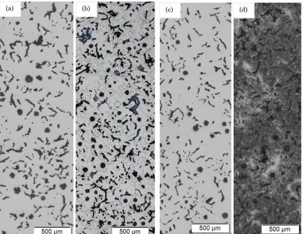
The samples of CGI were heat treated to obtain an optimum result in mechanical properties without changing microstructure of the graphite particles [22]. After the samples were heat treated, they were etched thus it influence on the surface profile at grain boundaries, which in results in microscopic inspection. From the figure 3 (a), it was observed that the polished samples show the mixed combination of flakes and spheroidal nodules. After etching, the microstructure of the austempered CGI was revealed as shown in figure 3(d), which signifies that the austempering was successful onto the samples, when compared to the etched conventional CGI as shown in figure 3(b).
Figure .3. Microstructure of CGI (a)Unetched Samples before austempering (b) Etched before austempering (c) Unetched samples after austempering (d) Etched samples after austempering (TA = 375 oC for tA = 60mins)
(c) (d)
(b) (a)
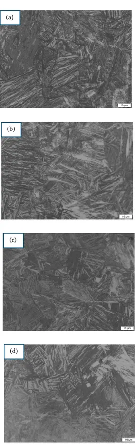
Figure 4 – Microstructural change during the austempering at 275oC for (a)30 (b) 60 (c) 90 and (d) 120 mins; austenitizing time of 60 mins.
Figure 5 – Microstructural change during the austempering at 275oC for (a)30 (b) 60 (c) 90 and (d) 120 mins; austenitizing time of 90 mins.
(b) (c) (d) (a) (a) (b) (c) (d)
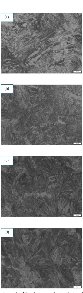
Figure 6- Microstructural change during the austempering at 325oC for (a)30 (b) 60 (c) 90 and (d) 120 mins; austenitizing time of 60 mins.
Figure 7 - Microstructural change during the austempering at 325oC for (a)30 (b) 60 (c) 90 and (d) 120 mins; austenitizing time of 90 mins.
(a) (a)
(b) (b)
(c) (c)
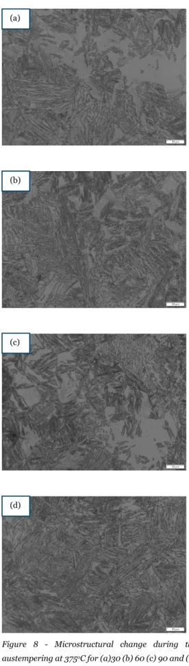
Figure 8 - Microstructural change during the austempering at 375oC for (a)30 (b) 60 (c) 90 and (d) 120 mins; austenitizing time of 60 mins.
Figure 9 - Microstructural change during the austempering at 375oC for (a)30 (b) 60 (c) 90 and (d) 120 mins; austenitizing time of 90 mins.
(a) (a)
(b) (b)
(c) (c)
From the figure (4, 5, 6, 7, 8, & 9), we observe that after material was heat treated, it forms a dark-needle shaped ferrite, known as acicular ferrite. The above figures represent the matrix of the austempered CGI, where the austenitising temperature is kept at 850oC with different times (60 and 90mins)
and austempered at different temperatures (275, 325 and 375oC), and different
time interval (30,60,90, & 120 mins). The acicular ferrite formation after the samples were etched shows the success of the austempering on the conventional CGI samples. In some pictures as shown in figure 8(a) and 9(a) there is visibility of lower bainites, whereas pictures shown in figure 4(a) and 5 (a) is fond of upper bainites. The visible white area is the untransformed austenite or retained austenite obtained after the heat treatment process. The untransformed austenite may form to martensite. The grey area etched region is identified as the carbon-enriched austenite [22].
4.2 Influence of the austenitizing temperature and time on the mechanical properties.
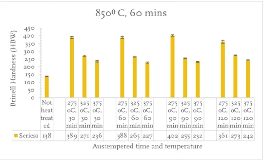
Figure 10 Brinell hardness test for different austempering time and temperature, at austenitization temperature 850oC and austenitizing time 60 mins.
Figure 11 - Brinell hardness test for different austempering time and temperature, at austenitization temperature 850oC and austenitizing time 90 mins.
Figure 12 - Vickers hardness test for different austempering time and temperature, at austenitization temperature 850oC and austenitizing time 60 mins.
Figure 13 - Vickers hardness test for different austempering time and temperature, at austenitization temperature 850oC and austenitizing time 90 mins
From the figure 10,11, 12, and 13, shows the austempering temperature and time on Brinell and Vickers hardness of the austempered CGI. It shows clearly that with an increase in austempering temperature, the microstructure become coarser. The coursing behavior with retained austenite results in reduction of hardness and strength value but increases the ductility and impact energy of the material [23] . After the heat treatment of the conventional CGI, the material shows a significant growth in the hardness values. Initially with conventional CGI showed a result of 138HBW for Brinell and 181HV for the Vickers hardness, but after the heat treatment, there have been a gradual increase in hardness value. It was noticed that the low austempering temperature shows higher mechanical strength compared to the high austempering temperature, this is due to the formation of fine acicular ferrite and low amount of austenite. The maximum hardness is both Brinell and the Vickers hardness was observed in the low austempering temperature (275oC) and minimum for the high
austempering temperature (375oC). There wasn’t change in the trend for all the
three austempering temperatures (275,325 and 375oC) with the increase in the
austempering time from 30 to 120 mins. The short austempering time has low fracture toughness but exhibits good hardness. From the results, the short time period (30 mins) was enough to produce the ausferrite structure in all the austempering temperatures. In the case of austenitising temperature 850oC and
austenitizing time 90 mins, there was slightly increase in the hardness which might be the formation of the retained austenite to ferrite and carbides.
Figure 14 - Tensile test to determine tensile strength over different austempering time and temperature, at austenitization temperature 850oC and austenitizing time 60 mins
Figure 15 - Tensile test to determine Yield strength over different austempering time and temperature, at austenitization temperature 850oC and austenitizing time 60 mins
Figure 16 - Tensile test to determine Young’s Modulus over different austempering time and temperature, at austenitization temperature 850oC and austenitizing time 60 mins.
Figure 17 - Tensile test to determine tensile strength over different austempering time and temperature, at austenitization temperature 850oC and austenitizing time 90 mins.
Figure 18 - Tensile test to determine Yield strength over different austempering time and temperature, at austenitization temperature 850oC and austenitizing time 90 mins.
Figure 19 - Tensile test to determine Young’s Modulus over different austempering time and temperature, at austenitization temperature 850oC and austenitizing time 90 mins.
From the figure (14,15,16,17,18 and 19) as shown above signifies the tensile trend which was evaluated using the MATLAB script to determine the ultimate tensile strength, yield strength, and Young’s modulus. The bar graph shows the mechanical properties at different austempering temperatures at different time interval. A similar kind of results has been observed as that of the hardness test that is with the decrease in the austempering temperature there is increase in the tensile properties. From the graph it is observed that the low austempering temperature (275oC) has the higher tensile and hardness value is due to the
strength and fatigue of the material [23]. But from the young’s modulus graph, it shows that there is not much of a difference under different austempering treatment conditions.
During the analysis of the stress strain curve under the tensile test, it was observed that the higher austempered temperature has significantly more elongation than that of the lower austempering temperature. With the increase in austempering temperature results in retained austenite and carbon enrichment, which results in elongation and ductility of the material. Whereas the lower austempering temperature results in low ductility but has comparatively higher hardness and tensile strength.
As it is a confidential document, it is not possible to show all the pictures and the graphs, but few of the tensile curves has been uploaded in the appendix.
4.3 Fracture surface analysis
The fracture surface of the tensile test of the samples of all the austempering treatment condition were analyzed by SEM studies. The figures shown above are the fractographs of the tensile test samples. The pictures reveal the ductile fracture for the higher austempering temperature (375oC) with some dimple
and cleavage fracture. It is observed that the fractures formed under all the austempering treatment conditions were tend to brittle fracture. The pictures reveal that the lower austempering temperature has the mixture of quasi-cleavage and dimple fracture which results in brittle fracture. However, the high austempering temperature reveal more dimple which indicates the ductility of the material.
Figure 20 – The fracture surface corresponding to austempered CGI, austenitised at 850oC for 60 minutes and then austempered at 275, 325 and 375oC. (a) (b) (c) (a’) (b’) (c’)
Figure 21 – The fracture surface corresponding to austempered CGI, austenitised at 850oC for 60 minutes and then austempered at 275, 325 and 375oC.
(a) (a’)
(b) (b’)
5
Discussion and conclusions
In this part the discussion and the conclusions of the methods as well as findings are made.
5.1 Discussion of method
The method of obtaining the Austempered CGI with the help of heat treatment was to obtain improved mechanical properties with compared with the conventional CGI. The acicular ferrite obtained after the heat treatment varies from the conventional CGI. To obtain the results, factors like time and temperature were taken in account. The samples were austenitised at 850oC for
60 and 90 mins, later they were austempered at 275, 325, and 375oC for 30, 60,
90 and 120 mins. The austenitization was performed under the furnace and the austempering was performed under the salt bath furnace.
To validate the results, analysis was performed to the austempered CGI to obtain the mechanical behavior. Microstructure analysis was performed for each austempered CGI sample on LOM. To obtain the mechanical properties, tensile and the hardness test was performed. The tensile test was performed on a constant engineering strain rate. While the hardness test was performed on two different tests. The hardness test used here were Brinell and Vickers Hardness and later pictures were taken under LOM for the analysis of the results. The tensile test performed onto the samples were then taken on for SEM for the fractography analysis.
5.2 Discussion of findings
The heat treatment performed onto the conventional CGI has obtained a significant improvement to the mechanical properties and shows the effect in the microstructure as well. It shows that with the increase amount of acicular ferrite, shows increase in mechanical properties. The conventional CGI was austenitised at 850oC for 60 and 90 mins, which was eventually it was
austempered at 275, 325, & 375oC for 30,60,90 and 120 mins. The austempered
samples when noticed under the LOM, showed a significant change in matrix structure, forming acicular ferrite. From the figure 4,5,6,7,8, and 9 shown above under the microstructure analysis has all obtained the acicular ferrite which signifies that the heat treatment performed onto the samples were successful.
It showed that lower austempering temperature (275oC) was enough to obtain
the acicular ferrite. The process window for the formation of the acicular ferrite under lower and higher austempering temperature is like that of the ADI as mentioned above the theoretical background.
The mechanical tests performed onto the austempered samples have shown significantly increase in the mechanical properties when compared to that of the conventional CGI. The trend shown in figure 10,11,12, and 13 as shown above under the hardness test, signifies that samples under the lower austempering temperature, the samples have higher hardness values, whereas the higher austempering temperature has significantly lower hardness values. Similar kind of trend is observed under the tensile test results. The samples with high carbon saturated austenite has significantly decreased in the hardness but improved ductility of the samples. Overall, the austempered CGI has improved mechanical properties when compared to the conventional CGI.
5.3 Conclusions
The austempering process performed on the conventional CGI has significantly improved the mechanical properties. The samples of low austempering temperature (275oC) resulted in more hardness and tensile strength when
compared to the samples of high austempering temperature but with the increase in austempering temperature results in increase in ductility of the material due to the high carbon stabilized austenite.
The heat treatment of the CGI from 275 to 375oC forms the acicular ferrite
along with retained austenite. With an increase in austempering temperature, the microstructure becomes coarser. The austempering at lower temperature (275oC) results in greater volume of acicular ferrite and low amount of austenite
which results in higher hardness and tensile strength, whereas the austempering at higher temperature results in coursing behavior with retained austenite which results in increase in ductility and impact energy. With the increase in austempering temperature from 275 to 325oC, the fracture
6
References
[1] I. Chakrabarty, "Heat Treatment of Cast Irons," in Comprehensive Materials Finishing.
Vol. 2, Varanasi, Elsevier, 2017, p. 246–287.
[2] S. SHEPPERSON, "THE ABRASIVE WEAR RESISTANCE OF AUSTEMPERED SPHEROIDAL GRAPHITE IRONS," University of Cape Town, pp. 1-100, 1987.
[3] R. Elliott, Cast Iron Technology, London: Butterworth & Co. (Publishers) Ltd., 1988. [4] R. Ghasemi, "A REVIEW OF AUSTEMPERING HEAT TREATMENT PROCESS OF CAST
IRON ALLOYS," in AusCGI project, Jönköping, 2019, pp. 1-30.
[5] C. S. S. &. W. T. Loper, "Graphite Inoculants For Gray Cast Iron," MRS Proceedings, pp. 34, 89, 1984.
[6] R. Elliott, Cast Iron Technology, Manchester: Butterworth & Co., 1988.
[7] J. Davis, "Classification and Basic Metallurgy of Cast Irons," in ASM Specialty Handbook
Cast Irons , 1996, pp. 4-12.
[8] R. a. H. Dixon, "Ferrosilicon magnesium alloy development for the production of S.G. iron by various processes," Brit. Foundryman, p. 77, 1984.
[9] A. P. Mouritz, "11 - Steels for aircraft structures," in Introduction to Aerospace Materials, Woodhead Publishing, 2012, pp. 232-250.
[10] M. Bepari, "Carburizing: A method of case hardeniing of steel," in Comprehensive
Materials Finishing, Elsevier, 2017, pp. 71-106.
[11] M. R. M. K. M. Ahmad, "Microstructure and Mechanical Properties of Austenitic Compacted Cast," EDP Sciences, pp. 1-7, 2015.
[12] A. S. A. S. Z. GLAVAS, "THE PROPERTIES OF SILICON ALLOYED FERRITIC DUCTILE IRONS," METABK, vol. 3, pp. 293-296, 2016.
[13] M. R. A. D. C. S. J. M. M. Martı´n, "Influence of Pearlite Formation on the Ductility Response," Metallogr. Microstruct. Anal, pp. 505-511, 2016.
[14] E. Y. T. N. D. H. Gungunes, "The effect of austenitizing time on martensite morphologies and magnetic properties of martensite in Fe–24.5%Ni–4.5%Si alloy," J Mater Sci, pp. 6102-6107, 2007.
[15] Z. Z. N. D. a. L. Y. Liu C, "A new empirical formula for the calculation of MS temperatures in pure iron and super-low carbon alloy steels," journal of Materials Processing
Technology, pp. 556-562, 2001.
[16] G. B. a. M. K. Aravind Vadiraj, "Structure and Property Studies on Austempered and As-Cast Ausferritic Gray As-Cast Irons," JMEPEG, pp. 976-983, 2016.
[17] S. J. R. a. G. W. G. Thomas G. Digges, "Heat Treatment and Properties of Iron and Steel,"
National Bureau of Standards Monograph 88, no. 11, pp. 1-45, 1966.
[18] R. V. a. Y. Lee, "PROPERTIES AND APPLICATION OF AUSTEMPERED DUCTILE IRONS," in CURRENT ADVANCES IN MECHANICAL DESIGN AND PRODUCTION , Cairo, PERGAMON PRESS , 1988, pp. 29-36.
[19] B. R. K. P.-T. a. V. A. B. Bosnjak, "Influence of Microalloying and Heat Treatment on the Kinetics of Bainitic Reaction in Austempered Ductile Iron," Journal of Materials
Engineering and Performance, vol. 10(2), pp. 203-211, 2001.
[20] H. &. C. J. M. Bhadeshia, "Bainite in steels," Springer-Verlag, 1990, pp. 767-797.
[21] H. S. M. Nili-Ahmadabadi, "Austempered Ductile Cast Iron: Bainitic ransformation in. In Encyclopedia of Iron, Steel, and Their Alloys," Taylor and Francis Online, pp. 217-230, 2016.
[22] I. H. A. G. a. A. D. Rohollah Ghasemi, "Austempered Compacted Graphite Iron — Influence of Austempering Conditions on Microstructure and Mechanical Properties," pp. 1-17, 2019.
[23] D. G. H. S. ,. D. D. V. P. P. Z. L. a. S. S. Prabhukumar Sellamuthu, "Austempered Ductile Iron (ADI): Influence of Austempering Temperature on Microstructure, Mechanical and Wear Properties and Energy Consumption," metals, pp. 1-12, 2017.
7
Appendix
Figure 22 – Stress vs strain curve corresponds to the austempered CGI, austenitised at 850oC for 60 minutes and then austempered at 275 oC for 30 minutes.
Figure 23 – Stress vs strain curve corresponds to the austempered CGI, austenitised at 850oC for 60 minutes and then austempered at 325 oC for 30 minutes.
Figure 24 – Stress vs strain curve corresponds to the austempered CGI, austenitised at 850oC for 60 minutes and then austempered at 375 oC for 30 minutes.
Figure 25 – Stress vs strain curve corresponds to the austempered CGI, austenitised at 850oC for 90 minutes and then austempered at 275 oC for 30 minutes.
Figure 26 – Stress vs strain curve corresponds to the austempered CGI, austenitised at 850oC for 90 minutes and then austempered at 325 oC for 30 minutes.
![Figure 1 Iron-carbon Equilibrium diagram. [3]](https://thumb-eu.123doks.com/thumbv2/5dokorg/4974030.136650/10.892.144.662.411.837/figure-iron-carbon-equilibrium-diagram.webp)

![Figure 2 Representation of the austempering reaction, (A) high austempering temperature, (B) low austempering temperature [21]](https://thumb-eu.123doks.com/thumbv2/5dokorg/4974030.136650/16.892.142.774.808.1032/figure-representation-austempering-reaction-austempering-temperature-austempering-temperature.webp)