ISSN 0347-6049
& VTIsärtryck
[_
1&
1990
Heavy Duty Vehicle Dynamics Related to
Braking, Steering and Tyres - Swedish
Research and Proposals by VTI
Olle Nordström
Reprint from SAE Technical Paper Series, SP 807 Vehicle
Dyna-mics Related to Braking and Steering, paper 892502, pp 43 57
(Truck and Bus Meeting and Expos/tion, Charlotte, North
Caro/ina, November 6 - 9, 7989)
w Väg'OCI' a /(' Statens väg- och trafikinstitut ( VTI) ' 581 07 Linköping
&. = The Engineering Society
For Advancing Mobility
Land Sea Air and Space®
I N T E R N A TI O N A L 400 COMMONWEALTH DRIVE, WARRENDALE, PA15096-0001 U.S.A.
892502
Heavy Duty Vehicle Dynamics Related to
Braking, Steering and Tyres
Swedish
Research and Proposals by VTI
Olle Nordström
Swedish Road and Traffic Research Institute
Linkoping, Sweden
Reprinted from SP-801 Vehicle Dynamics
Related to Braking and Steering
Truck and Bus Meeting
and Exposition
Charlotte, North Carolina
SAE GLOBAL MOBILITY DATABASE
The papers included in this volume are abstracted and indexed in the
SAE Global Mobility Database.
No part of this publication may be reproduced in any form, in
an electronic retrieval system or otherwise, without the prior
written permission of the publisher.
ISSN 0148-7191
Copyright 1989 Society of Automotive Engineers, Inc.
Positions and opinions advanced in this paper are those of the
author(s) and not necessarily those of SAE. The author is
solely responsible for the content of the paper. A process is
available by which diScussions will be printed with the paper
it it is published in SAE Transactions. For permission to
publish this paper in full or in part, contact the SAE
Publica-tions Division.
Persons wishing to submit papers to be considered for
pres-entation or publication through SAE should send the
manu-script or a 300 word abstract of a proposed manumanu-script to:
Secretary, Engineering Activity Board, SAE.
892502
Heavy Duty Vehicle Dynamics Related to
Braking, Steering and Tyres
Swedish
Research and Proposals by VTI
Olle Nordström
Swedish Road and Traffic Research Institute
Linkoping, Sweden
ABSTRACT
Research concerning heavy duty vehicle
dynamics related to braking, steering and tyres has been conducted by the Swedish Road and Traffic Research Institute (VTI) for
about 20 years. The aim has been to develop
test procedures and propose minimum per-formance requirements primarily for vehicle combinations. This paper summarizes results concerning dynamic stability in a double lane
change manouevre at constant speed,
over-turning stability, emergency antilock braking performance under winter conditions in terms of stability, steerability and braking per formance during emergency braking in a turn on ice and during straight line braking on ice, split friction and transition from low to high friction. Hybrid simulation and a tyre tester are also described.
THE SWEDISH ROAD AND TRAFFIC RESEARCH INSTITUTE (VTI) is a governmental research
organization dealing with research and test-ing concerntest-ing road buildtest-ing, traffic engine"
ering, human factors, road vehicles and
lately also some railway research. The road vehicle research is mainly safety oriented and deals with both
crash-worthiness and crash avoidance problems.
Since about 20 years great emphasis has been laid on research concerning the dynamic per-formance of heavy vehicle combinations.
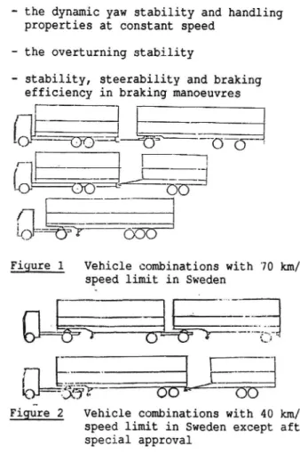
The great majority of Swedish heavy vehicle combinations consists of a truck and a full trailer with a permissible total length of 24 m. This type of combination as well as tractor and semitrailer and truck and centre axle trailer combinations has a speed limit of 70 km/h (Figure 1).
Combinations with two trailers have a
speed limit of 40 km/h (Figure 2). Individual
approvals for 70 km/h can however be obtained
if certain technical specifications are
ful-filled. These restrictions are by Swedish
43
industry transport research organizations
(IVA TFK, Volvo) regarded as a major
obstacle for an improvement of the road transport system in Sweden.
The VTI research has to a large degree
been motivated by the actions of these
organizations and the concern of the road safety authorities to ensure that the level
of road safety is maintained or improved. The research has primarily dealt with the following problem areas.
- the dynamic yaw stability and handling
properties at constant speed
- the overturning stability
- stability, steerability and braking efficiency in braking manoeuvres
-; 3
[&_ 004475
O O r .{C}
r§() u
{BE§""
(
it, "" ' '='?
000
Figure 1 Vehicle combinations with 70 km/h
speed limit in Sweden
. - ...i ... _ ' ... -....-" ...,4!"*Ii. Cf ) Z 5 '~....' F lf k Figure 2
Tr
555?
00 W"
00
Vehicle combinations with 40 km/h
speed limit in Sweden except after special approval
Special interest has been taken in evaluating the performance on ice covered roads.
The aim of this paper is to review this research and give the present VTI position
concerning desirable performance and methods
of testing and legislative enforcement,
DYNAMIC STABILITY AT CONSTANT SPEED
1970 72 full scale experiments and computer simulations were made with combina tions with up to three articulations. The
dynamic stability was tested by means of a
double lane change manoeuvre (Figure 3). This
maneuvre was chosen as it was regarded as the
most severe in real traffic.
In the simulation the motor vehicle was steered by an automatic controller called DAVIS in such a way that the lateral
acceleration of the c.g. followed a
prescri-bed sinusoidal curve with 1.75 m/s2 as
maximum value.
As a result of these studies VTI proposed
that minimum performance requirements in this manoeuvre should be set for heavy vehicle
combinations (1, 2, 3)*. These were the
following:
- rearward amplification of side slip angles
should not exceed 2 related to the mean value of the tractor rear axles
- the side slip angles must not exceed 150
mrad (8,6°)
- the oscillatory damping must be such that all side slip angles are less than 20 mrad
(1,15°) when the front axle is 75 metres away from the entrance of the exit corridor
- the overturning risk must be smaller than 1. (No wheel lift must occur)
- the lateral axle deviation must stay within certain limits ensuring that the vehicle combination stays on a 7 m wide road
In the period 1972 to 1981 further
development of the simulation program was made (4) and new simulation studies were made
including about 400 heavy vehicle
combina-tions (7, 8, 9).
The simulation studies that have been made indicate that few articulation points are desirable. At the same time other para-meters were just as important from stability point of view. It is desirable to have
speed 70km/h mox lood mox c 9 height
3,5m Mu lxxoncomingjgta _
-3,5m?-_
%
___________
l10 40m
J.
obstdcle
Figure 3 VTI double lane change test. Full scale configuration
*Numbers in parentheses designate references
at the end of the paper
- a short distance between dolly pintle hook
and the first semitrailer rear axle (or load centre of the rear axles in the case
of multiple axles)
- long wheelbase on the trailers
- high tyre cornering stiffness which in-creases proportional to the load
- a low centre of gravity height high roll stiffness
- optimized roll or side force steer on the trailer axles as it has a significant
effect
These findings agree with later studies made at UMTRI in Michigan USA and in
Australia, Canada and England and the Federal Republic of Germany.
In 1981 a final report (10) was
publish-ed. The recommendations in the report were basically the same as 1972 but in addition an approval system based on simulation results was outlined in more detail.
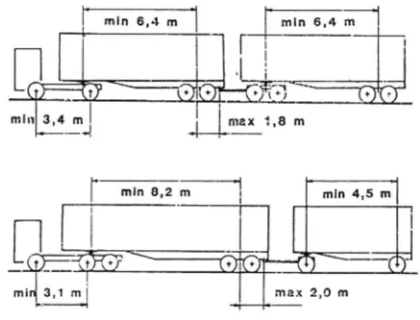
In 1984 the test procedure was used in full scale experiments on ice in comparative
testing (13). The results indicated that
suitably designed A-train type (Figure 4) double combinations could perform as well as or slightly better than a typical Swedish truck and full trailer combination in the terms of maximum speed without exceeding the track limitations. The truck full trailer combination which happens to have far from optimal dynamic performance could negotiate the track at 60 km/h with trailer skid as
limiting factor. The doubles could do 60 and
65 km/h. The lower performance was limited by
understeer of the three axle tractor probably
caused by too high friction in the fifth
wheel turntable. The doubles were also tested
with the yaw motion of the dolly relative to the first semitrailer eliminated.
min 6,4 m
min 6,4 m
U
mi max 1,8 m
max 2,0 m
Figure 4 Recommended A-train configuration 1984
This prevention of dolly jackknife did
however not improve the lane change per-formance in terms of maximum speed.
Based on these tests and other
considera-tions it was decided to give provisional permits for double combinations of the tested configurations or with more favourable design to be driven at speeds up to 70 km/h, Special
requirements were also set for the brakes
that had to be equipped with load sensing valves and/or an antilock system.
In 1986 and 1988 further lane change tests on ice were made with two special double combinations in order to have them approved for 70 km/h. The first combination had a yaw restrained centre axle trailer as second trailer (Figure 7, vehicle No. 13). The other combination was a conventional A-train with a short wheelbase three axle
tractor where the non driven middle axle was
tested steered and rigid. The test results were regarded as successful and were very similar to those obtained in 1984 i.e. about
65 km/h limit speed. In these tests a single
three axle truck was used as a reference. This vehicle performed marginally better. The limiting factor for the double combinations was trailer swing of the rearmost trailer. In the 1988 the yaw angle velocity rearward amplification was measured to be 1.6 at the rearmost trailer. No clear preference concerning steered or rigid tractor middle axle was found in this test.
In 1989 it has been proposed that double combinations should be approved for 70 km speed limit on a self certification basis if they fulfilled certain performance demands. The vehicles would have to be equipped with
ECE/EEC approved antilock brake systems.
The dynamic stability and steerability
would be approved by means of a computer
simulation of the double lane change developed by VTI. A more user friendly version of the program is planned to be developed for this purpose.
The performance requirements are somewhat changed compared with those originally pro-posed in 1972 in order to allow a simpler practical validation of the simulation test results if needed.
- The maximum allowed rearward amplification is still 2 but the reference variable has been changed to yaw velocity instead of side slip angle
- The limitation of lateral axle deviation is unchanged
- Also as before the overturning risk must be
lower than 1. This means that no wheel lift
must occur.
Tyre cornering stiffness characteristics have an important influence on the simulation results. These characteristics vary with tyre type but also with road surface and inflation pressure.
45
In order to safeguard for these varia-tions the simulavaria-tions are to be made with
reference tyre data which represent the lower
limit of what can be expected on a wet
asphalt or concrete road in normal condition.
Presently used values of cornering stiffness
are however higher than those used in the studies earlier presented by VTI and based on
more recent measurements.
The double combination with best stability performance is expected to be of the so called B-train concept with only two articulation points where the second semi-trailer is coupled directly to a fifth wheel at the rear end of the first semitrailer. It is however still important to keep the axle load centre of the first semitrailer close to the fifth wheel for the second semitrailer.
In Sweden several applications have been made for approval of combinations consisting
of a tractor, a semitrailer and a centre axle
trailer. Unlike the typical B-train rear semitrailer where the load is placed between the axles the centre axle trailer has a considerable load platform length behind the axle centre. On such a trailer it is possible to get the centre of gravity behind the
trailer axle(s) which would give a tendency
to oscillatory instability above a critical speed which could very well be within the operating speed. The experience with this kind of combination seems to be very small and no literature on the subject has been
found.
OVERTURNING STABILITY
Compared to a passenger car the
overtur-ning stability of a loaded heavy duty vehicle is very low. The most critical cases are when the cargo density is such that a vehicle height of 4 m or even more can be utilized. From safety point of view a high overturning limit is obviously desirable. Against this stands the desire to be able to carry the largest possible load volume and weight. In Sweden the maximum combination length is 24 m and the maximum weight is 51 400 kg. This is longer and heavier than in any other European
country but the load per metre vehicle length
is lower and allows for a lower c.g. height.
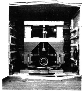
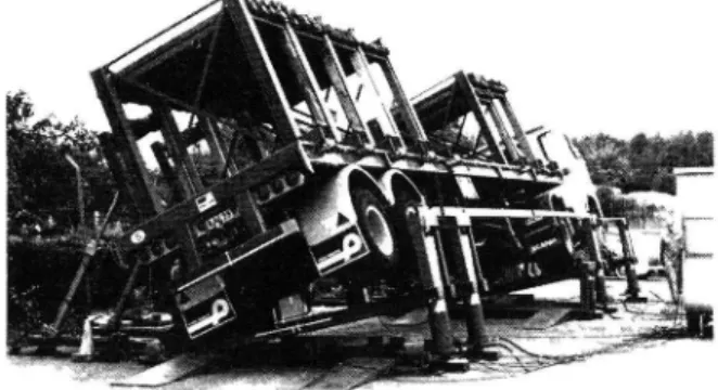
After full scale static tests of a number
of representative Swedish trucks and trailers
on a hydraulic tilting device (Figure 5), VTI in 1972 proposed a static overturning limit
of 4 m/sz.
Further studies were considered necessary and were also carried out but did not change
the new recommendation given in 1981 (10).
Since then investigators in USA, Australia and Canada have come to similar conclusions.
The effects of sloshing in partly filled road tankers have also been investigated by
VTI (5, 6). Scale 1:10 model tanks of
different shapes with and without longitudi-nal baffles were subjected to lateral motion
controlled by a computer program.
The liquid forces and accelerations were
measured and used as feed back input to the program, which simulated a double lane change manoeuvre and sinusoidal motions with varying
frequencies (Figure 6). With 50% load volume
it was found that the increase in overturning risk compared to a rigid load could be up to somewhat more than two times. Tests with different numbers and shapes of longitudinal baffles showed that three vertical baffles
increase the resonance frequency well above
the region that can be expected in the vehicle.
Still no regulations concerning over-turning stability exist in Sweden. However the proposal concerning a simulated lane
change test incorporates a maximum allowed
c.g. height, determined by the manufacturer,
for the different units in the combination. By definition the tractor will be subjected
to a maximum lateral acceleration of 1.75 m/s2 in the lane change. With an assumed
rearward amplification of 2 the rearmost trailer could then be exposed to 3.5 m/s2 which must not result in a wheel lift.
LABORATORY
EQUIPMENT 4
CCELEROMETER
The proposed regulation also incorporates
a requirement to state the static overturning stability of the laden trailers.
A recent decision to increase the maximum combination weight to 60 000 kg makes c.g. height limiting regulations still more
im-portant.
STABILITY, STEERABILITY AND BRAKING EFFICIENCY IN BRAKING MANOEUVRES
In order to ensure desirable accident avoidance performance it is necessary that the braking system of a heavy duty vehicle and especially of a heavy duty vehicle combi nation can be applied with full control force and still maintain stability and steerabili-ty. At the same time a high utilization of available road friction must be obtained. This is valid for all load and friction conditions.
Conventional braking systems without load sensing valves for heavy vehicles will tend to give wheel locking at emergency braking on low friction and with the vehicle unladen also on high friction. These problems can be reduced but not eliminated by load sensing
valves.
In Sweden these valves were once made
mandatory for heavy vehicles but were not
successful. The functional problems
especially on trailers were so great that the requirement was abandoned. Despite improved technology load sensing valves have still not gained any popularity on a voluntary basis
except perhaps for airsprung vehicles.
The braking characteristics of heavy
vehicle combinations in Denmark, Finland, Norway and Sweden were investigated by road
and laboratory brake tests on in total 400
combinations (21) randomly selected from the
FORCE TRANSDUCERS
I
/ HYDRAULIC __;(3: H SERVO <13 /'/'/ /U r7/ /' ////////7//////7/ /// /////7/ t INERTIA FORCESELIMINATION OF TANK LIOUID FORCES AND MOMENT
REFERRED TO TANK CENTRE
INTERFACE
I SCALING I SCALING TUTT' _'7F ANALOGUE COMPUTER 4 OPERATIONS VEHICLE MODEL INDEX OR VEHICLE MODEL INDLX OS VEHCILE MODEL INDEX VR
II
EVALUATION PREDFTERMINED MANOEUVRE RECORDING DAVIS OR HARMGHIC
Figure 6
IN
#
J
Scale model simulation of lateral sloshing in road tankers (from VTI Report No 82A)
traffic on suitable roads.
The theoretical advantage of load sensing valves could not be confirmed in this study. On the contrary the results indicate that maladjustments still is a significant problem that reduces the braking efficiency at full load and still gives wheel locking at almost the same deceleration as for vehicles without these devices. The trailers were in general underbraked relative to the truck or tractor especially at high pressures.
Poor brake adjustment resulting in long
pushrod stroke was one of the reasons for
poor braking efficiency despite mandatory automatic adjustment. Very short strokes were also associated with a reduction in braking efficiency. In Sweden ligtly laden vehicles showed significantly smaller braking
force/pressure ratio than fully laden vehicles. As these vehicles had no load sensing valves the results could indicate glazing effects due to the low brake forces used in the unladen condition which then re-covered when in the laden condition after a transition period. There is however a possi-bility of bias if drivers with laden vehicles
with poor brakes or overload were warned by
their colleagues and changed their route.
The VTI conclusion is that closed loop
brake control systems with a warning signal to the driver in case of malfunction is an important part of the solution to the present brake system problems.
An antilock brake system is an example of such a system designed to prevent wheel lock-ing due to overbraklock-ing. This solves the
problems of stability and steerability in an
emergency braking situation. Normally also the braking performance is improved. Under
non locking condition these systems are how-ever, inactive. A system for automatic brake
force adaptation between a truck and a full trailer has been introduced on the Swedish market by the Swedish company VBG under the name Bromsgyro. This system is fully
contained on the truck and consists of a coupling force sensor, a variable pressure reduction valve driven by an electric motor and a controller. A display shows the driver
the degree of pressure reduction and whether
the trailer is over-or underbraked in rela-tion to the truck.
SWEDISH PROPOSAL FOR COMPLEMENTARY WINTER SERVICE REQUIREMENTS TO BE ADDED TO THE NEW ECE REQUIREMENTS FOR ANTILOCK BRAKING SYSTEMS
(ABS)
In Sweden icy roads can be expected about
six months of the year. Safe braking under these conditions is a considerable problem.
Antilock braking systems with good
per-formance on ice are therefore expected to
give a significant reduction in traffic accidents where braking is involved.
The United Nations Economic Commission
for Europe (ECE) has developed a large number
of international road vehicle regulations.
47
The ECE Regulation No 13 adresses brakes and
contains since 1979 an annex concerning re-quirements on antilock brakes. A revised version became effective in 1987. The same rules have also been adopted by the European
Economic Community (EEC) in 1986.
Sweden took active part in the establish-ment of the revised version of the ECE-antilock regulation but has still not adopted it in its national legislation. The author of this paper represented Sweden in this work and has also been responsible for several
studies (11, 12, 13, 15, 17, 18, 19) concer
ning antilock system performance under winter conditions carried out by the Swedish Road
and Traffic Research Institute(VTI).
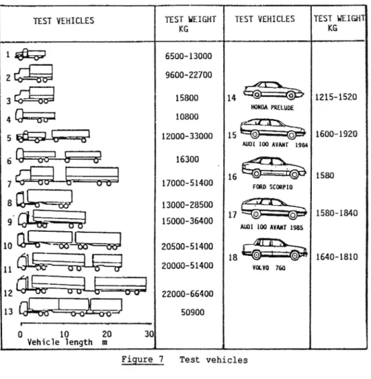
The VTI investigations have been made with heavy vehicles and vehicle combinations
from about 5 000 to more than 65 000 kg as well as for a number of passenger cars as
shown in Figure 7. Five different antilock systems for heavy vehicles and three for
passenger cars have been tested.
Based on these investigations winter service test methods and requirements are
proposed to be added to the
ECE/EEC-regula-tions. These are:
J-turn braking test on ice
- Split friction test with very low friction
on one side
- Straight line braking on ice
- Transition from low friction to high fric-tion surface
A hybrid laboratory test is envisaged as a future possibility of checking these
per-formances for electronic antilock systems. In
this test the vehicle is stationary and
connected to a computer.
In the following, these winter test
procedures and requirements are presented. J TURN TEST ON ICE
GENERAL - Vehicles with antilock system also on the steered wheels will if they meet the requirements of a straight braking
efficiency test certainly possess some degree of steerability. On very low friction sur-faces a bad antilock system may, however, give either very poor stability or very poor steerability, due to high slip levels and poor slip distribution between front and rear
axles. In both cases the expected safety
benefits will not be obtained and in the unstable case it might even be more dangerous to use such an antilock system than a conven-tional brake system or an antilock system acting only on the rear wheels. It is
there-fore essential to test the steering qualities
during emergency braking on low friction in a special test.
This is also important for trailers as the steerability and stability of a vehicle
combination also depends on the performance of the trailer.
A driver controlled J turn test is pro-posed. Open loop tests were found to be too severe for heavy vhicles which are normally somewhat oversteered during antilock braking. A J-turn test is less space demanding than a steady state circular test
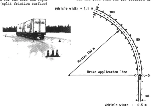
TEST SPECIFICATION - The driver controlled
J turn test on ice (Figure 8) has the
follow-ing specifications.
- The track surface shall consist of ice with a lateral friction corresponding to a maximum cornering speed between 40 and 60 km/h
- The test track shall have a 30 m long entrance corridor, 0.5 m wider than the
vehicle, followed by a 100 m radius
circular track 1.5 m wider than the vehicle
The test procedure comprises:
- determination of maximum cornering speed
without braking (VM)
- determination of the maximum speed (V0) and
the deceleration (ax) at which the vehicle
can be braked with ABS and full pedal force
Optional reference tests are:
- locked wheel straight line braking from 40 km/h on the same surface
- determination of an ECE type maximum constant deceleration in the turn without wheel locking from 75 % of VM based on front axle braking
PERFORMANCE REQUIREMENT - The following
stability/steerability performance is
proposed:
- to stay within the track boundaries with all parts of the tyre treads
- not to exceed a steering correction of +/-180°
- to have a stability/steerability factor ES
not less than 0.64 where ES=(VO/VM)2, i.e.
successful braking from 80% of the maximum cornering speed
the braking efficiency EBY = aX/ay, with
the maximum cornering acceleration (a ) as reference, is proposed to be at least 0.5
- the braking efficiency EBE = ax/aECE, based
on the maximum deceleration, with front
brakes only, to be at least 0.75
TEST VEHICLES TEST HEIGHT TEST VEHICLES TEST HEIGHT
10 Misc-Q
11 w
12 Må: #
13 l-<r-.vli W.vb Lo-02150134]
0 10 20 30 Vehicle length mKG
KG
1 &;
5500 13000
2 Egg
9600 22700
"Id. .3 31%
15800
1 14 "GD G
1215-1520
HONDA PRELUDE4 Gig)?!
10800
A -N
12000-33000 15 *@ -@ 1600-1920 AUDI 100 MIMI 198415 "om-cw . 1580
roan SCORPIO|
17000-5140013000 28500
GI. ___ 158 1840
_ __ O.. 15000-36400 17 () C) AUDI 100 AVANT 1985 20500-51400 IUD. .. |18 ©" ©* _ 1640-1810
20000-51400 VOLVO 750I
22000 66400 50900Figure 7 Test vehicles
the braking efficiency EBE = ax/aECE, based
on the maximum deceleration without wheel locking, to be at least 0.75
The test is also proposed for trailers which shall be tested in combination with a worst case approved antilock motor vehicle.
TEST RESULTS - Results from the closed
loop J-turn test are presented in Figure 9 and 10.
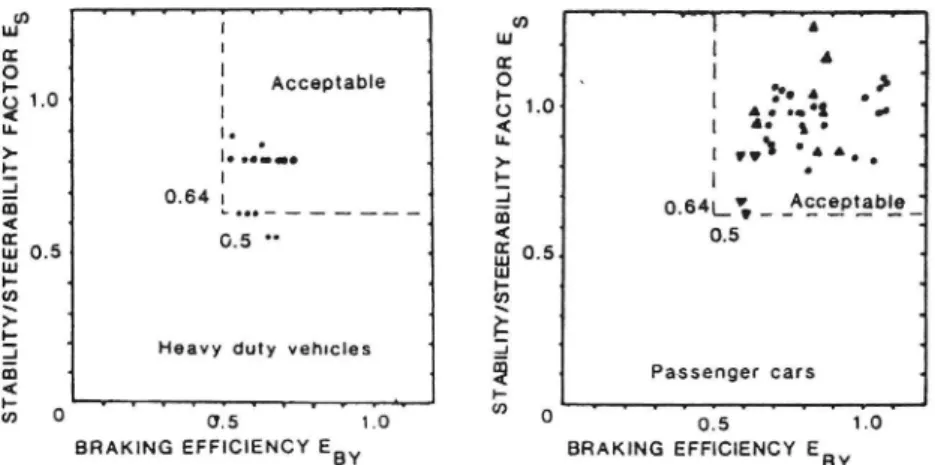
Figure 9 illustrates the relationship between the stability/steerability factor Es and the braking efficiency EBY for passenger cars and heavy duty vehicles.
Figure 10 presents the relationship between ES and EBL also with separate results
for passenger cars and heavy duty vehicles. The diagrams show no correlation between
the stability/steerability factor and the braking efficiency. Results from tests with increasing initial speed have, depending on the tyre equipment, given both increasing and decreasing braking efficiency. From the dia-grams can be seen that if all results were to be accepted. ES should be at least 0.5 in stead of the proposed at least 0.64. The latter choice is based on the opinion that
this value is more representative for the
state of the art. The vehicles that did not meet this requirement should be improved.
SPLIT FRICTION TEST WITH VERY LOW FRICTION ON ONE SIDE
GENERAL - In order to reduce cost and to reduce yaw moment and torque effects in the
steering when braking on a surface with different friction for the left and right hand side wheels (split friction surface)
Vehicle width + 1.5 m
antilock systems have been made with only one
regulator per axle that adjusts the brake force on the axle to the lowest friction. This is called "select low" control. When the friction is very low as for instance on ice this can result in extremely long braking distances compared to individual wheel braking. This is shown in Figure 11 which also illust-rates that the present ECE/EEC regulation is not very efficient as well as the improve-ment achieved with a proposed change origin-ating from WABCO.
TEST SPECIFICATION The split friction test which is already part of the ECE/EEC-regulations is illustrated by Figure 12. The
test track consists of two parallel tracks,
one with a high friction Kl and the other with a low friction K2. The test is performed from an initial speed of 50 km/h in three steps.
The two first steps give the values of Kl and K2 by means of maximum constant pedal force single axle braking without wheel lock-ing. The third step gives the split friction
braking ratio Z3. (Braking ratio = decelera
tion/9.81). The ECE/EEC performance
require-ments are:
- a maximum lateral displacement where no
parts of the tyre treads cross the common track boundary
- a maximum steering correction of 120° within the first two seconds and 240° during the rest of the stop
a minimum braking ratio Z3 = 0.75(4K2+K1)/5 but not less than the low friction K2
Brake application line
30
Vehicle width + 0.5 m Figure 8 J-turn antilock braking test with driver control. Test track
Acceptable _ _ _ _ _ _ . _ 1 0.64 | * L... ___..____._ 0.5 0. _o a: A L L L A
Heavy duty vehicles
L f ' r f 1.0 BY ST AB IL IT Y/ ST EE RA BI LI TY F A C T O R ES 0 '03 . BRAKING EFFICIENCY E Figure 9 ' f ' WT ' 'n ' ' T Lu 4 I _ g 4 | A , 'i p. "e A
01-0
' .:..oz '..
( | 4. g o u. i o' , >. 1 | " . .. . . : | ' £ * v Acceptabie ' 2 * 0.64å_5 _ _ __ __ _ __ 5 05. Lu |... U) \E
..J 1 $ Passenger cars q$
° os LO BRAKING EFFICIENCY EBYJ-turn antilock braking test with driver control. Test results
showing stability/steerability factor and braking efficiency EBY
v v v v v v v v f '
Heavy duty vehicles
ST AB IL IT Y/ST EE RA BI LI TY F ACT O R E s Tito 2.0 ' BRAKING erncneucv ESL
O d O -. . -A A Acceptable ___ 1 0.64 [___ 0.9 0.5 i Passenger cars * S T A B I L I T Y / S T E E R A B I L I T Y F A C T O R E s vvv f v w ' 'i vf 0 1.0 2.0
BRAKING EFFICIENCY EBL
Figure 10 J turn antilock braking test with driver control. Test results
showing stability/steerability factor and braking efficiency EBL
The last requirement in combination with an allowed ratio K2/K1 as high as 0.5 is a major weakness in the regulation as it allows an efficient "select low" system to
pass the test.
PROPOSAL FOR WINTER CONDITION
REQUIRE-MENTS - As a realistic compromise it is pro posed that the braking efficiency formula should be based on the actually achieved antilock braking ratios Z1 and ZZ instead of
75% of K1 and K2 and become Z3 = 0.2(4Z2 +
Zl). It is also proposed that the ratio ZZ/Zl must not exceed 0.4 and Z2 not exceed 0.15.
It is furthermore proposed that the
applic-able requirements should also be met by trailers as they can represent a large part
of the total combination mass.
The trailer should be tested together with a representative towing vehicle equipped with an approved antilock system. The braking efficiency of the trailer should also be tested by means of separate trailer braking.
When 21, Z2 and 23 are calculated, the
rolling resistance of the towing vehicle can be set to 0.015 for driven wheels and 0.010 for non driven wheels.
TEST RESULTS - VTI has performed tests on split friction surfaces with ice as low
50 m . 150* B R A K I N G D I S T A N C E F R O M 5 0 K M / H Fth hic on coef K1-0.5
High friction braking ratio Zi-O.5 ow friction braking ratio Z2-K2
__Select low control 28-2 2
ECE/EEC requirement 23å0.75(4K2+K1)/5 23>K2 w ABCO requirement 23å(422+Z1)/5 individual contro|23=0.5(21+22) O
03
ota
0:3
014 015
01.6
LOW FRICTION COEFFICIENT K2
0,7
friction surface and sand bonded to the ice
with water as high friction surface. The peak friction coefficients were about 0.1 and 0.6 and very similar locked wheel values. The tests took place during six winters from 1980 to 1988. The tested vehicles are shown in Figure 7. The systems represent different control strategies from "select low" to
indi-vidual wheel control. _
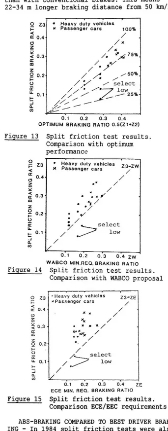
The test results are shown in Figure 13,
14, and 15.
In Figure 13 the braking ratio Z3 obtained in the split friction test is
compared to the optimum braking ratio defined
as (Zl + Z2)/2. The braking ratios Z1 and Z2
are those obtained by antilock braking tests on the high and the low friction surfaces.
It can be seen that the "select low" systems have a braking efficiency of only
27-45% of the optimum braking compared to values between 67 and 90% for systems with higher degree of individual wheel control.
In Figure 14 the braking ratio Z3 is compared to the minimum required in the WABCO
proposal. The tested vehicles with select low
ABS did not meet this requirement.
In Figure 15 test results are compared to the ECE/EEC requirement. This is easier to
meet than the WABCO proposal.
INFLUENCE OF TYPE OF TRAILER ABS The
ECE/EEC antilock regulations do not have a split friction test for trailers. This means that trailers with axle by axle "select low"
type ABS may be used even when individual
control ABS is required for the towing vehicle. VTI has carried out tests in 1988 (19) with a partly laden truck weighing 16400 kg and a fully laden trailer weighing 22600 kg. The truck had an individual control ABS and the trailer had two versions of the same ABS. One version had "select low" control and the other individual control. Tests with the conventional system only were also made. On the split friction track the tests with the
ECE/EEC : K1min=0.5 K2max=0.5K1
zaao.75(4K2+K1)o.2 232
5:3
LOW FRICTION K 2E
VID-80 km/h ... ... ... ... ... ... ... ... ...MAX STEERING CORRECTION
cafe
TIME T 0 2 sek z-Tstop sek
K2max 10.40 K1 or Z2max =0.40 21 zazo.2(422+21) PROPOSED NEW W|NTER SERVICE REQUIREMENTS
Figure 12 Split friction test procedure
51
select low system gave 25% lower decelera-tion than with individual system and 40% less than with conventional brakes. This means 22-34 m longer braking distance from 50 km/h.
0 23 0 Heavy duty vehicles
C at Passenger cars 10095
*
/
01 O.4< . 0 /x3
x
x< o 3
/. "')4 75%.
å
./
J
s
/ ')
/so..
d; 0.2
/ A
/
9 ///// // select m- 0.1 /£//' //% / 2595+low | / /&,
1///
OH
05
05
&4
OPTIMUM BRAKING RATIO 0.5(Z1+22) Figure 13 Split friction test results.
Comparison with optimum
performance
' Heavy duty vehicles
x Passenger cars N w zs-zvv /' o ? \\ 9 w . / .° ro select low \ X = . . .
V
SP LIT FR lC TI ON B R A K ING RA TI O071 o.'2 o.'3 o.'4 zw WABCO MIN.REO,BRAKING RATIO
Split friction test results. Comparison with WABCO proposal
Figure 14
r v 1 ,
O 23 'Heavy duty vehicles ZB'ZE
: xPassenger cars / ( n: 0 4 x / . o " / E & / f 0.3 . xx x x / * a: xc ; .. &/,/' 9 0-2' .- / 4 * ' /' o E />selict U- 0 1 ow » / ' : / a. co
6.1
ofz
0.13
074
25
race MIN. nee. samme mmo Figure 15 Split friction test results.
Comparison ECE/EEC requirements
ABS-BRAKING COMPARED TO BEST DRIVER BRAK
ING - In 1984 split friction tests were also
carried out in order to compare performance
with and without antilock system. Four unladen heavy vehicle combinations (vehicles
6, 7, 10 and 11 in Figure 7) were used. All
but one (prototype system) were equipped with load sensing valves and WABCO antilock
but each combination was tested by only one
driver.
The result of these tests was that the
braking efficiency in most cases was 10-20% higher with the normal braking system than with the antilock system in operation. The efficiency of the antilock systems was about
80% of (Z1+Z2)/2. Both with and without
anti-lock system it was possible to keep the
vehicle within a 3.5 m lane. The steering and
braking task was, however, more difficult without antilock system. The maximum steering angles were about 90° with and 135° without antilock system.
STRAIGHT LINE BRAKING ON ICE
GENERAL - Straight line braking on a homo geneous surface is the classic and basic way of testing the braking performance of
vehicles. The ECE/EEC antilock braking
regulations prescribe straight line low fric-tion tests. The fricfric-tion level is however allowed to be as high as 0.4. A test on ice
is therefore regarded as a useful winter
service approval requirement.
TESTS CARRIED OUT BY VTI - Straight line
antilock braking tests on ice have been made in comparison with
- locked wheel braking
best driver control braking
- peak friction measured with single axle braking according to ECE/EEC antilock
regulation (see Figure 16 and 17) measured
at 40 and 20 km/h. BV11 had a 4.00-8 tyre and BV12 a 5.60-15 PIARC "Europe" tyre both
with rib tread, in accordance with ISO TR
8349 on friction measurement
Tests have been made from initial speeds ranging from 70 to 35 km/h for trucks and
trailers and, for passenger cars from 110 to
50 km/h.
Most of the tests have been done in the temperature range -5°C to -20°C but tests have also been made near 0°C and down to -30°C. Except in 1980 the tests have been made on ice roughened by the special multi-wheel trailer with studded passenger car tyres shown in Figure 18. The treatment
Reference
wheel
Figure 16 Friction test trailer BV11
Figure 17 Friction test vehicle BV12
results in a somewhat higher and more uniform friction and reduces polishing effects which tend to lower the friction.
RESULTS - The results are summarized in
Figure 19, 20, 21, 22 and 23.
From the figures can be seen that as a
rule the braking efficiency with antilock systems is higher than with locked wheels and
higher than best driver performances. In
tests with laden and unladen vehicles the unladen vehicles tend to get higher deceleration but not necessarily higher braking efficiency based on peak value.
The 75% efficiency required by ECE/EEC
regulations is not always met on ice by anti-lock systems for heavy vehicles. For the tested passenger cars with and without studs the efficiency is close to 100%.
Longitudinal friction coefficients
obtained with the reference tyres on friction test vehicles BV11 and BV12 according to the
Figure 18 Multiwheel trailer with studded passenger car tyres for ice conditioning treatment
>-2C) ' f . IO
tå
3515' p Ml uni öm G 4 P LI35310>å
u.I0:0 5
_
En:
mIJJEE:
DO 'f'fova'vu-yr fffffffff Z ::.: 0 0.5 1.0 1.5 2.0 .AE§3/Z Lock STRAIGHT LINE BRAKlNG EFFICIENCYFigure 19 Straight line antilock braking efficiency in relation to locked wheel braking
(ZABS/KBVH 00
50
100
150
usjouyjqoujqoug
A A 1 L A PL LLLLLLLLLMama/0073 ]107
avs- 0.17/0.17 _]100
Egon/0,069 1112
(gig 0,15/0,17 J_8_8
%0J16/0980 ' 1146
%OJWO.
J100
Figure 20 Straight line antilock braking Figure 21 Straight line antilock braking test results. Comparison with test test results with standard tyres.
driver performance Comparison with friction test
trailer BV11
0
(ZABS/KECE)10
A A A4 A 1 L LLLLLLLLL
& 0,17/0,16 105 (Z IK )100
&
O'mm ig ,
0,21/0,2O 106 ABS BV12.-.5.0....199..15.9
0.11/0.09
j123
.a O.17/0,16 7106
(350.17/0231 74
(gm/0.16 94
LQ_¥0,15/0,14
]107
% O,17IO.18 94
Figure 22 Straight line antilock braking Figure 23 Straight line antilock braking test results. Comparison with test results with standard tyres. ECE/EEC friction coefficient Comparison with friction test
vehicle BV12 53
constant slip method gave the same values as the peak friction coefficients obtained by single axle braking according to ECE Regula-tion 13 both for a truck and a passenger car with standard tyres (upeak=0.17).
DISCUSSION - According to Annex 10 in ECE Regulation 13 normal brakes are allowed to have a braking efficiency of 50% at a fric tion coefficient of 0.2. It could therefore be debated if the efficiency requirements on antilock systems on ice should be as high as
75% of the peak friction coefficient. The
test results indicate that 90% of the locked wheel friction could be a more suitable requirement. A locked wheel test is also the simplest and least expensive alternative. In order to avoid stability problems the locked wheel braking tests on ice are recommended to be done from an initial speed of 40 km/h.
PROPOSAL FOR A STRAIGHT AHEAD BRAKING TEST
ON ICE - Based on the field test experience and theoretical considerations the following test is proposed.
Test surface-The test surface should be ice with a locked wheel friction of 0.1 +/-0.05 measured with the test vehicle itself or the friction test vehicle BV11 or equivalent
equipment. Roughening of the ice by means of
the special multi-wheel trailer according to Figure 18 is recommended. The air and ice surface temperature should be below 0°C, preferably between -5 and -15°C.
Test speed-The initial speed should be 40 km/h vehicles for tyres without studs and 50 km/h for tyres with studs (additional test for passenger cars).
Braking tests-Locked wheel and antilock braking stops should be made with a pedal force that on high friction would give at
least 5 m/sz. The mean value of the results
from at least three tests of each type should
be used for the efficiency calculation. For each test the mean deceleration is calculated by the formula ä=5.56/T m/s2 where T is the time for V=35 km/h to V=15 km/h.
Minimum requirement on braking
efficiency-äABs/äL z 0.9 or (ths/ZLOCK)20.9
äABS = Mean deceleration with the antilock
system operating. ZABS = äABs/9.81
äL = Mean deceleration with all wheels
locked. ZLOCK = äL/9.81
Trailer tests-Trailer tests should be made by braking only the trailer and correcting for the rolling resistance of the towing vehicle. The rolling resistance coefficient for nondriven wheels may be assumed to be 0.010 and for driven wheels 0.015.
Alternative test method Tests may also be performed according to the procedure pre-scribed by ECE/EEC regulations but on the same ice surface. It is considered as more difficult to carry out and meet the require-ments of this test.
54
TRANSITION TEST FROM LOW TO HIGH FRICTION
GENERAL - When a vehicle with normal brakes is braked on very low friction and suddenly encounters a transition to a high friction surface the braking torque applied by the driver is immediately fully utilized up to the limit of adhesion for each axle as they pass on to the new surface.
In the same situation but braking a vehicle with an antilock system fully adapted to the low friction there is a risk that the pressure recovery might be very slow and result in an unacceptably long braking distance compared with a normal braking system. The new ECE/EEC antilock braking regulations therefore demand a test in this
respect. The requirement on the high/low
friction ratio is however only 2:1 which is low for winter service conditions.
TESTS CARRIED OUT BY VTI - Tests with one
heavy duty truck antilock system on ice with very low friction resulted in pressure drops to near zero with recovery rates of not more than 3 bar/sec that could not be influenced by a sudden transition to high friction. This corresponds to about 1.5 3 to reach 4.5 m/s2 deceleration. Transition tests with other systems indicate that 0.7 s is a reasonable target from a technical point of view.
DISCUSSION - If the vehicle deceleration is measured the wheelbase has to be taken into account. At 50 km/h an additional time delay of 0.7 s will cover all practical cases. A total deceleration transition time from 1.5 m/s2 to 4.5 m/s2 of 1.5 3 for heavy duty vehicles and 1.0 s for passenger cars
has been considered to be a reasonable
requirement for winter service.
PROPOSED WINTER SERVICE TEST - The test
shall be made with full brake application at a pressure that corresponds to a deceleration
of at least 5 m/s2 starting on a low friction
surface which must not give the vehicle a higher deceleration than 1.5 m/s2 with the antilock system in operation. The vehicle speed at the transition to high friction must not be less than 50 km/h. The high friction
surface must allow an antilock braking
deceleration of at least 4.5 m/sz. This deceleration must be reached within 1.5 s for heavy duty vehicles and within 1.0 3 for passenger cars. This time is measured from the front axle transition time.
HYBRID LABORATORY TESTING ' A FUTURE TYPE APPROVAL PROCEDURE?
The practical difficulties are consider-able both technically and economically in obtaining test tracks that give the desired friction characteristics and are large enough for safe high speed and cornering tests. In fact they are so severe that ECE/EEC regula-tions regard peak friction coefficients up to 0.4 at 40 to 50 km/h as low and do not
tyre/road adhesion. Furthermore the problems
connected with brake lining characteristics
must not be forgotten.
For antilock systems with electric wheel speed signals these problems can be eli-minated by real time computer simulation of
the tyre/road characteristics, brake torque
characteristics and vehicle motion dynamics
including wheel speed sensor signals. The
real vehicle that is to be tested is
connected to the computer through an inter-face so that the simulated wheel speed signals are received by its antilock system controller and the wheel brake cylinder pressures measured by sensors on each wheel are fed back to the computer. During the test the vehicle is stationary in the laboratory with the engine running. The test engineer has only to apply the brakes after starting
the computer program.
This technique has been used by VTI with promising results. At present it is possible to simulate:
- Straight braking on a homogeneous surface - Straight braking on a split friction
sur-face with steering corrections based on yaw motion
- Braking during steady state cornering with constant steer input
J-turn braking with constant steer input applied at the same time as the brakes - Braking on a surface with changing
fric-tion can also be simulated as the computer
programme contains two tyre models for each wheel
Validation simulations have been made
with a two axle truck with an unladen weight
of 6 500 kg and a laden weight of 13 000 kg. The vehicle was equipped with three different types of antilock systems. This vehicle was also used in the already mentioned tests on real ice tracks, split friction tracks as well as on high friction tracks. The
following tests were used for the validation: - Straight braking on homogeneous ice.
Initial speed 10 and 20 m/s
- Straight braking on a split friction surface. Initial speed 10 m/s
- J-turn braking on ice with constant steering input corresponding to 100 m radius applied at the same time as the brakes. Initial speed 11 m/s
- Straight braking on a high friction sur-face with the peak friction coefficient 0.6. Initial speed 20 m/s
In all the tests the ranking order in
performance was the same in simulation and
real test. The general characteristics in
terms of deceleration, lateral acceleration
and yaw behaviour over time were also quite well reproduced. This also applies to wheel
speeds and brake pressures. Test were made
both with identical tyre data on front and rear wheels and with somewhat reduced fric-tion on the rear wheels. The best results were obtained in the latter case. This is in line with the fact that ice friction is reduced by the polishing effect of slipping tyres. In this case the front tyres polish the ice for the rear tyres. It is not believed that this method of testing can replace real world tests but it looks promis-ing as a future complement for evaluatpromis-ing antilock system performance under conditions that are too difficult, expensive or
dange-rous to require in real type approval tests.
New soft-and hardware with a specially
designed parallel processor system has recently been developed at VTI (20). The purpose was to reduce the computing time for
wheel velocities and tyre forces from 5 to 1
ms and at the same time allow for more wheels
and more detailed tyre data. The system is however not yet incorporated in the hybrid ABS-simulation program.
TRUCK TYRE TEST FACILITY
Truck tyre data are very important for the simulation of heavy vehicle dynamics. In order to be able to obtain these data in a
well controlled environment a truck tyre test
facility with capacity for testing on ice has been built at VTI. The test wheel rig is stationary (Figure 24) and the test track is
a flat 50 m long moving steel beam. The maximum speed is at present about 10 m/s. Maximum wheel load is 10 000 kg and lateral and longitudinal forces up to 70 000 N can be measured. The side slip angle can be varied
up to 90° at up to 30°/s. Ice temperatures
down to -20°C are possible. The facility became operational in May 1989 but has so far only been used for evaluating passenger car winter tyres. The first truck tyre measure ments are planned for the autumn 1989.
CONCLUSIONS
The dynamics of heavy duty vehicles and especially heavy duty vehicle combinations has since a long time been regarded as an im-portant area of research by VTI and will probably remain so for a long time.
The main investigation areas have been - yaw stability and steerability at constant
speed
- overturning stability with rigid and liquid load
- stability, steerability and braking efficiency during emergency braking - tyre - road friction characteristics
The behaviour of heavy vehicle combina-tions under severe winter condicombina-tions has a high priority due to the climatic conditions in Sweden.
Road and computer simulation test methods and performance requirements have been in-vestigated proposed for legislation use with the aim to promote safe vehicles on our roads.
REFERENCES
The Dynamic Stability of Heavy Vehicle
Combinations. VTI Report No. 9, Part 1 and 2. (In Swedish) VTI, Linköping, Sweden 1972
2. Nordström O., Strandberg L.
The Dynamic Stability of Heavy Vehicle
Combinations. VTI Report No. 67A. VTI,
Linköping, Sweden 1974
3. Strandberg L., Nordström O., Nordmark S.
Safety Problems in Commercial Vehicle
Handling. VTI Report No. 82A. VTI, Linköping,
Sweden 1975
4. Nordmark S.
Computer Program for Digital Simulation of a Double Lane Change Manoeuvre with a Heavy Vehicle Combination.
list of figures in English) VTI Report No.
96. VTI, Linköping, Sweden 1976
Nordström O., Magnusson G. and Strandberg L.
(In Swedish. Summary and
56 10. 11. 12. 13. 14. Lidström M.
Road Tanker Overturning - with and without
longitudinal baffles. (In Swedish. Summary
and list of figures in English) VTI Report No. 115. VTI, Linköping, Sweden 1977
Strandberg L.
Lateral Stability of Road Tankers. Volume I Main Report. Volume II Appendices. VTI Report No. 138A. VTI, Linköping, Sweden 1977
Nordmark S., Nordström O.
Lateral Dynamics of Truck and Full Trailer Combinations. Paper presented at OECD
symposium on Heavy Freight Vehicles and their Effects. Nov. 1977
Nordmark S., Nordström O.
Lane Change Dynamics versus Geometric Design of Truck and Full Trailer Combinations - a Computer Study. Paper presented at XVII FISITA Congress in Budapest 1978
Nordström O., Nordmark S.
Test Procedures for the Evaluation of the
Lateral Dynamics of Commercial Vehicle Combinations. Automobile Industrie No. 2, 1978
Nordström O., Nordmark S.
Handling Caracteristicts of Heavy Vehicle Combinations at Constant Speed. Final Report.
(In Swedish) VTI Report No. 234. VTI,
Linköping, Sweden 1981
Nordström O.
Antilock systems for heavy vehicles - State of the art, test methods and
regulations.(Extensive Summary in English) VTI Report 257. VTI, Linköping, Sweden 1983
Palmkvist G., Nordström O.
Hybrid Laboratory Test Method for Antilock Systems. The Dynamics of Vehicles on Roads and Railway Tracks. Proceedings 8th
IAVSD-Symposium Cambridge Mass USA 1983.
Swets & Zeitlinger, Lisse, Holland
Nordström O., Ståhl P.
Field testing of "double combinations" under
winter conditions. STU Report. (In Swedish)
VTI, Linköping, Sweden June 1984
Oppenheimer P.
The development of international antilock braking regulations. IMechE Conference on
Anti-lock braking systems for road vehicles Paper C190/85. IMechE Conference Publications 1985-8. Mech Eng Publ Ltd. London 1985
. Nordström O.
16. 17. 18. 19. 20. 21.
1985 for evaluation of draft revision of ECE Reg. 13 Annex 13. (Extensive Summary in English) VTI Report 304. VTI, Linköping, Sweden 1986
ECE Regulation 13, Annex 13. Addendum 12: Regulation 13 to be annexed to the Agreement Revision 2 - Amendment 3. Supplement 1 to the 05 series of amendments which entered into force on 1 April 1987. E/ECE/324 Rev 1/Add 12/Rev 2/Amendment 3. United Nations, Geneva 1987
Nordström O.
Antilock system performance under winter conditions-what should be required ? 11th ESV Conference Washington DC May 12-15 1987 Nordström O.
Antilock Braking System Performance. International Regulations Now and in the Future - Some Swedish Viewpoints. Paper presented at TRB - VTI Conference "Road and Traffic Safety on Two Continents" 1987. VTI Report 332A. VTI, Linköping, Sweden 1988
Nordström 0.
Test methods and Requirements for ABS on Heavy Duty Trailers suited for Nordic Winter
Conditions. (In Swedish) VTI Notat TF 50 10.
VTI, Linköping, Sweden 1988 Palmkvist G.
Parallel Processor System for Real Time
Simulation. Automotive Simulation.
Proceedings of the 2nd European Cars/Trucks Simulation Symposium Schliersee, FRG, May 1989. Springer-Verlag, Berlin, Heidelberg,
New York, London, Paris, Tokyo 1989 Strandberg L.
Braking Characteristics of 400 Heavy Trailer Combinations from Denmark, Finland, Norway
and Sweden. 12th ESV Conference, Gothenburg,
Sweden 1989
Positions and opinions advanced in this paper are those of the
author(s) and not necessarily those of SAE. The author is
solely responsible for the content of the paper. A process is
available by which discussions will be printed with the paper
it it is published in SAE Transactions. For permission to
publish this paper in full or in part, contact the SAE
Publica-tions Division.

![Figure 19 Straight line antilock braking efficiency in relation to locked wheel braking (ZABS/KBVH 00 50 100 150 usjouyjqoujqougAA1LAPL LLLLLLLLL Mama/0073 ]107 avs- 0.17/0.17 _]100 Egon/0,069 1112 (gig 0,15/0,17 J_8_8 %0J16/0980 ' 1146 %OJWO](https://thumb-eu.123doks.com/thumbv2/5dokorg/4893240.134174/15.892.279.710.89.358/figure-straight-antilock-braking-efficiency-relation-usjouyjqoujqougaa-lllllllll.webp)