Master Thesis
Software Engineering
Thesis no: MSE-2007-19
June 2007
Analyzing Suitability of SysML for System
Engineering Applications
Saleem Zubair Ahmad
School of Engineering
Blekinge Institute of Technology
Box 520
SE – 372 25 Ronneby
Sweden
School of Engineering
Blekinge Institute of Technology
Box 520
SE – 372 25 Ronneby
Internet :
www.bth.se/tek
Phone
: +46 457 38 50 00
Fax
: + 46 457 271 25
University advisor:
Ludwik KuzniarzDepartment of Systems and Software Engineering Blekinge Institute of Technology School of Engineering 372 25 Ronneby, Sweden
Contact Information:
Author:
Saleem Zubair Ahmad
Address: Folkparksvagan 15:11 37420, Ronneby, SwedenE-mail: szah06@hotmail.com
This thesis is submitted to the School of Engineering at Blekinge Institute of Technology in
partial fulfilment of the requirements for the degree of Master of Science in Software
Engineering. The thesis is equivalent to 20 weeks of full time studies.
A
CKNOWLEDGEMENT
No project could ever get started, without help from a lot of wonderful people. The author wishes to express sincere appreciation to Dr. Ludwik Kuzniarz for his kind assistance in the preparation of this thesis. I would like to thank Dr. Robert Feldt for his technical gaudiness in this thesis. Especially thanks to OMG at www.omg.org for making an incredible platform for modeling and make it possible to access valuable articles for public. In addition, special thanks to all those people whose familiarity with the needs and ideas of this thesis was helpful during the early phase of this undertaking. Thanks also to my mother and friends for their valuable input.
A
BSTRACT
During last decade UML have to face different tricky challenges. For instance as a single unified, general purpose modeling language it should offer simple and explicit semantic which can be applicable to wide range of domains. Due to significant shift of focus from software to system “software-centric” attitude of UML has been exposed. So need of certain domain specific language is always there which can address problems of system rather then software only i.e. motivation for SysML. In this thesis SysML is evaluated to analyze its suitability for system engineering applications. A evaluation criteria is established, through which appropriateness of SysML is observed over system development life cycle. The study is conducted by taking case example of real life i.e. automobile product. Results of research not only provide an opportunity to get inside into SysML architecture but also offer an idea of SysML appropriateness for multidisciplinary product development
C
ONTENTS
ACKNOWLEDGEMENT ... I ABSTRACT ... II CONTENTS ...IV 1 INTRODUCTION ... 1 1.1 BACKGROUND... 11.2 AIMS AND OBJECTIVES... 1
1.3 RESEARCH QUESTIONS... 2
1.4 EXPECTED OUTCOME... 2
1.5 ASSUMPTIONS... 3
1.6 RESEARCH PLAN... 3
1.7 THESIS OUTLINE... 3
2 A COMPARATIVE STUDY; SYSTEM ENGINEERING VS SOFTWARE ENGINEERING ... 5
2.1 SYSTEM ENGINEERING... 5
2.1.1 System Engineering Process... 6
2.1.1.1 State the Problem: ... 6
2.1.1.2 Investigate Alternatives... 6
2.1.1.3 Model the system ... 6
2.1.1.4 Integrate ... 7
2.1.1.5 Launch the system... 7
2.1.1.6 Assess performance... 7
2.1.1.7 Re-evaluate ... 7
2.2 SOFTWARE ENGINEERING... 8
2.3 SYSTEM ENGINEERING VS. SOFTWARE ENGINEERING... 9
2.4 WHY SYSML? ... 10 3 SYSML ARCHITECTURE ... 12 3.1 STRUCTURE... 14 3.2 BEHAVIOR... 15 3.3 REQUIREMENT... 16 3.4 PARAMETRIC... 16 3.5 CROSS-CUTTING CONSTRUCTS... 16 4 UML VS SYSML ... 18
4.1 ELEMENTS INTRODUCED BY SYSML... 20
4.1.1 Requirements Diagram ... 20 4.1.2 Parametric Diagram... 21 4.1.3 Allocations ... 21 4.1.3.1 Behavioral Allocations... 21 4.1.3.2 Flow Allocation... 22 4.1.3.3 Structural allocations... 22 4.2 EXTENSIONS... 22 4.2.1 Activity Diagram... 22 4.2.1.1 Probability:... 22 4.2.1.2 Rate: ... 22 4.2.1.3 Optional: ... 23 4.2.1.4 Continuous: ... 23 4.2.1.5 Discrete: ... 23 4.2.1.6 Control Operator: ... 23 4.2.1.7 No Buffer: ... 23 4.2.1.8 Overwrite: ... 23 4.2.2 Block Diagrams ... 23 4.2.2.1 Labeled compartments ... 24
4.2.2.2 Constraints compartment... 24
4.2.2.3 Namespace compartment ... 24
4.2.2.4 Structure compartment ... 24
4.2.3 Ports and Flows... 24
4.2.3.1 Standard Ports ... 24
4.2.3.2 Flow Ports ... 25
4.2.3.3 Item Flows ... 25
4.2.3.4 Outcome... 25
5 DEVELOPMENT OF EVALUATION CRITERION... 26
5.1 EVALUATION CRITERIA FOR SYSML ... 26
5.2 IBM RAIN SENSING WIPER (RSW); CASE STUDY... 27
6 APPLICATION OF CRITERIA ON SIMILAR... 29
6.1 STATE THE PROBLEM... 29
6.2 INVESTIGATE ALTERNATIVES... 33
6.3 MODEL THE SYSTEM... 35
6.4 INTEGRATIONS... 40
6.5 LAUNCH THE SYSTEM... 42
6.6 ASSESS PERFORMANCE. ... 44
6.7 RE-EVALUATION... 47
7 DISCUSSION AND FUTURE WORK ... 49
7.1 DISCUSSION... 49 7.2 VALIDITY THREATS... 52 7.2.1 Internal validity ... 52 7.2.1.1 Maturation threats ... 52 7.2.1.2 Testing threats ... 52 7.2.1.3 Selection threats ... 52 7.2.2 Construct Validity ... 52 7.2.3 External Validity ... 53 7.2.4 Conclusion Validity ... 53 7.3 FUTURE WORK... 53 8 REFERENCE: ... 54 APPENDIX I ... 57 APPENDIX II ... 58 APPENDIX III... 59 APPENDIX IV ... 60 APPENDIX V... 61
LIST OF FIGURES
Figure 1 System Engineering Process [9] ...6
Figure 2. Relationship between UML and SysML [1]. ...12
Figure 3 . SysML Diagram Taxonomy [1]...13
Figure 4. Notation to represent Diagram in SysML [18] ...13
Figure 5. Four Pillars of SysML [18]. ...14
Figure 6. Allocation relationship[18] ...17
Figure 7. Comparison of UML and SysML diagrams [26] ...19
Figure 8. Use case diagram for RSW. [33] ...29
Figure 9. Requirement Diagram for RSW [33]...32
Figure 10. Parametric models for windshield[33]...34
Figure 11. RSW Block Definition Diagram [33] ...37
Figure 12. Internal Block Diagram (IBD) RSW[33]...38
Figure 13. Allocations [33] ...39
Figure 14.Ports and Interfaces[33]...41
Figure 15. Test case for RSW [33]...43
Figure 16.Constraints Blocks for RSW [33]...45
1
I
NTRODUCTION
1.1
Background
As a foundation of MBD, the Unified Modeling Language (UML) has been widely adopted by academia and industry since it was introduced by Object Management Group (OMG) in 1995 and became de facto standard within the software engineering in the following years. Although UML was initially developed for software Engineering, it is also suitable for describing processes and products and potentially for System engineering together with other languages such as SysML [3,2].
Actually the Systems Engineering is an interdisciplinary approach and means to enable the realization of successful systems by collaboration of several disciplines like hardware, software, and personal. It focuses on defining customer needs and required functionality early in the development cycle, documenting requirements, then proceeding towards design activities and system validation while taking into account the complete problem: The elements of the systems engineering regulation are not new. many of the systems engineering concepts, such as a structured approach and traceability of design towards requirements, have been applied to small system
development for many years. The major factor which distinguishes Systems
engineering is the scale and complexity of the target systems. The huge complex systems are composed of dissimilar "subsystems", which may in turn be large and complex, and require further systems engineering to meet their cost, schedule, and performance objectives. The system complications have been grown up due to increased functionalities and complex relationships between different disciplines. [11, 1]
The International Council of System Engineering (INCOSE) defines the System engineering as “Systems engineering integrates all the disciplines and specialty groups
into a team effort forming a structured development process that proceeds from concept to production to operation. Systems engineering considers both the business and the technical needs of all customers with the goal of providing a quality product that meets the user needs” [11].
The above mention definition could be used to describe the characteristics of the modern industry where several engineering disciplines are integrated with employing different techniques concurrently. System engineers searches a domain specific modeling language to specify a complex systems because System may also include non-software components such as hardware, information, personnel, process and facilities. UML is software bias so UML cannot satisfy the needs about non software systems. Hence need for certain domain specific language like SysML become more obvious because it is believed that SysML may satisfy all needs of complex system including different types of sub-systems. [4]
1.2
Aims and Objectives
The System Modeling Language (SysMLTM) is strongly related to UML due to fact that SysMLTM is developed through customization of UML for System engineering [1].
In general we easily observed two most important deficiencies in UML from a system engineer's perspective i.e. poor support for data flow, and the difficulty in describing system architecture. System engineers often use data flow concepts, both to describe overall behavior, and to define the key algorithms in system control. The only tool that they currently have in UML is the Activity Diagram, which implements very few of the true dataflow concepts and is aimed at class design, rather than system design. Engineers are also concerned with accurately representing the frequently complex architecture of the total system, something that the current deployment diagram is not representing truly [7] [1].
The aim of research is to observe how the SysMLTM can be used to support the development of system engineering application.
The following are aims and objectives of research.
1. Developing of tutorial for SysML for the purpose of understanding and getting inside into language architecture.
2. Selection of appropriate elements through which SysML can be analyzed.
1.3
Research Questions
To achieve aims and objectives, research is focused to explore the effectiveness of SysML for system engineering applications. The main research question is
1. Why SysML is more suitable then UML for system engineering applications?
. It should be noted that UML is a general purpose language and can be utilized for modeling system engineering applications, so main research question is designed in such a manner that through this question additional capabilities of SysML can be focused. The phrase “more suitable” in question highlighted fact that UML has some potential for solving complex system engineering problems. Deficiencies of UML in addressing system engineering issues can also be investigated through this question. Actually this question is designed with the aim to investigate and verify the claim of OMG and INCOSE that SysML remove drawbacks of UML in order to address system engineering issues more precisely and accurately.
Before addressing main research question, following sub-questions will be addresses as pre-requisite in order to get inside into details of different involving concepts.
a) What does make System Engineering more comprehensive then software engineering?
b) Why four Pillars are included in SysML Architecture? And what is their contribution?
c) What are the key modifications made by SysML in UML structure?
Through First sub question a comparison between system engineering and software engineering will be established. This study will help in identification of those aspects through which system engineering is considered to be a broader discipline than software engineering. actually this comparison will provide basis for comparing two languages i.e. SysML and UML. Architecture of SysML will explored thorough second sub question. Investigation regarding justification of presence of four pillars i.e. structure, behavior, parametric and requirement will be conducted. How SysML makes changes in exiting structure of UML, this will be investigated by third sub question. Actually three sub question are formulated in such a way that they not only established solid background for answering main research question but also but also give an opportunity to investigate different aspects of SysML.
1.4
Expected Outcome.
Thesis will contain consolidating knowledge for answering research questions and will make inquiry, documentation and analysis of the SysML including identification of possibilities and obstacles to adopt SysML by considering one or more domain specific system functions.
In short we can expect following in report. • An understanding and explanation of SysML.
• A justification of effectiveness of SysML for system engineering applications.
1.5
Assumptions
Following two important assumptions have been made regarding this study. 1. Readers of this research document should have good idea of UML.
2. Readers must familiar with some concept about system engineering particularly INCOSE contributions towards system engineering.
1.6
Research Plan
Actually it is a comparative study containing two noteworthy comparisons first; system engineering vs. software engineering and then UML vs. SysML. The research will be conducted in following steps.
• First, a comparison between system engineering and software engineering will be established. The study will be conducted in light of exiting knowledge relating to these two disciplines. Study will also explore different phases of SIMILAR [9, 34] (system engineering process recommended by INCOSE) [11].Basic theme of study is to compare capabilities and domain of these disciplines and decide which is more suitable for current industrial scenario. • Conduction of investigations regarding architecture of SysML with respect to
its four pillars i.e. structure, behavior, requirement and parametric. After this exploration, a comparative study between UML and SysML will be conducted by keeping in view following points.
1. Which elements are common in UML and SysML? 2. Which new elements are including in SysML? And why? 3. Which elements are left out by SysML from UML profile?
Out of elements which will come out while answering above mentioned questions, three elements will be considered for further study and to address research questions more precisely i.e. Blocks, Parametric, and Requirement. This will be done to make research more precise and time feasible.
• An evaluation criterion will be derived from exiting knowledge [35] to judge the capabilities of SysML for addressing complex industrial problems.
• Selection of appropriate case study [14] to support research result, which will be produced by the application of evaluation criteria on different phases of SIMILAR [9, 34].
• Implementation of evaluation criteria on SysML in context of SIMILAR [9, 34]. Study will aim at, to observe how SysML support system engineering activities in each phase of SIMILAR [9, 34].
1.7
Thesis outline
The thesis is planned out in following chapters.
Chapter 1; This chapter provides introduction and background of study, describing research plan and highlighting some basic assumptions regarding study.
Chapter 2; In this chapter, comparative study regarding system engineering and
software engineering has been described. Further more SIMILAR i.e. system engineering process and motivation for adopting system engineering in current industrial scenario is also described.
Chapter 3; It contains structural information regarding SysML architecture,
identifying significant elements in SysML structure and also provides justifications for their presence.
Chapter 4; It provides details about the new elements introduced by SysML and
also provides idea about some major extensions made by SysML in exiting UML structure.
Chapter 5; This chapter gives details about case study ‘rain sensing wiper’; an
automobile system. Formulation of evaluation criteria for judgment of effectiveness of SysML is also described in this chapter.
Chapter 6; How SysML is evaluated through newly derived criteria in context of
SIMILAR; this is major theme of this chapter.
Chapter 7; This chapter presents conclusions of study and describes some future
2
A
C
OMPARATIVES
TUDY;
SYSTEM ENGINEERING VS SOFTWARE ENGINEERINGInternational Council of System Engineering (INCOSE) [11] adopted the definition of [Rechtin, 2000] for defining system in modern industrial context “A system is a construct or
collection of different elements that together produce results not obtainable by the elements alone. The elements, or parts, can include people, hardware, software, facilities, policies, and documents; that is, all things required to produce systems-level results. The results include system level qualities, properties, characteristics, functions, behaviour and performance. The value added by the system as a whole, beyond that contributed independently by the parts, is primarily created by the relationship among the parts; that is, how they are interconnected.”[9]
A system is consisting of different individual elements like people, hardware, software, facilities, policies, and documents. The outputs given by system are qualities, properties, characteristics, behaviour, functions and performance. System consists of software and non-software elements [9]. In short, system is a collection of different related components which are trying to achieve one common objective. However it should be noted that computerized system is comprised of elements like hardware, software, people, facilities, and data [10]. So, it become obvious that software is an element of system that has only software intensive tasks.
2.1
System Engineering
The collaboration among several disciplines is an emerging/important trend faced by the modern Industrial circles. The complications in system structures have been grown up due to augmented functionalities and complex relationships between different disciplines. There are so many complex relationships among different functions/components of the system furthermore, during products development different methodologies and different tools are used due to the different design patterns and traditions for each discipline.
Actually the Systems Engineering is an interdisciplinary approach and means to enable the realization of successful systems. It focuses on defining customer needs and required functionality early in the development cycle, documenting requirements, and then proceeding with design synthesis and system validation while considering the complete problem [11]. The elements of the Systems Engineering discipline are not new. Many of the systems engineering concepts, such as a structured approach and traceability of design to requirements, have been applied to small system development for years. What distinguishes systems engineering is the scale and complexity of the target systems. The large complex systems are composed of "subsystems", which may in turn be large and complex, and require further systems engineering to meet their cost, schedule, and technical performance objectives.
Traditionally system engineering is defined “The set of activities which oversees the development process, ensuring that the product requirements are complete and fully satisfy the customer’s needs.”[12]
However keeping in view the characteristics of the modern industry where several engineering disciplines are integrated with employing different techniques concurrently INCOSE define the System engineering as “Systems Engineering integrates all the disciplines
and specialty groups into a team effort forming a structured development process that proceeds from concept to production to operation. Systems engineering considers both the business and the technical needs of all customers with the goal of providing a quality product that meets the user needs.” [9]
2.1.1
System Engineering Process
Actually responsibility of system engineering is to establish such a efficient interdisciplinary processes which can easily ensure that customer need are satisfied within prescribed deadline, preserving highest level of quality and in a cost effective manner.
For this purpose INCOSE describe system engineering process which usually called SIMILAR process as shown in Fig 1.[9]
Figure 1. System Engineering Process [9]
The word SIMILAR is actually acronym for following seven different activities which constitute this process. [9]
1. State the problem /problem definition
2. Investigate alternatives / find alternatives to solve problem 3. Modelling the system
4. Integrating the system 5. Launching the system 6. Assessment of performance 7. Re-evaluation
Customer
Needs
State the
Problem
Investigate
Alternatives
Model the
System
Integrate
Launch
the System
Outputs
Re-evaluate
Re-evaluate
Re-evaluate
Re-evaluate
Re-evaluate
Assess
Performance
Re-evaluate
2.1.1.1 State the Problem:
In this stage our major focus what should do with out involving thinking how it will be done. Normally problem statement is more concentrated on functional requirements but we can also take in to account important non-functional constraints. Problem statement should be written in a sense that it can be traceable. Simplification is another important property of problem statement because all kind of stakeholder will interact with this statement so difficult language must be avoided in writing this statement. [9]
2.1.1.2 Investigate Alternatives
Consideration of alternatives is always very important particularly if to different performance goals and want to avoid different mishaps and risk in connection with time and cost. However it should be noted that selection of alternatives should be made in a very careful manner and they must be judge against requirement very strictly. [9]
2.1.1.3 Model the system
Modelling activities will be conducted to capture deeper knowledge about different alternatives. The model make thing more visible and manageable. Engineers may relay on several kind of models like Mathematical models, state machine models, Block Diagrams and object-oriented Models. It should be noted that system engineering is not process but it focus on product as well. So Models of product are also developed to analyze different factors like risk management, trade-offs functionalities. However it should be kept in mind that system engineering process is iterative so Modelling will continue through out life cycle. [9]
2.1.1.4 Integrate
It is clear that system engineering is an interdisciplinary approach so integration among different discipline and sub-system is central issue in system engineering process. Basic theme of integration is to relate different components create overall structure of system. system engineering always emphasis on well-organized integration of different to avoid any mishap during integration engineers must establish feed back loop to get correct any fault as early as possible.[9]
2.1.1.5 Launch the system
In this phase system is thrown into working environment i.e. it allow to do for which it is developed, different alternative are also kept in mind. The aspect of human interaction is very important at this stage because operators (human) can easily assess performance test different types of functionalities offered by system. Some parts of system bought from market (COTS) these gains special attention of engineering at this phase because they always interested in analyzing capabilities of these part in actual environment.[9]
2.1.1.6 Assess performance
Performance assessment is one of the key areas of system engineering, for this purpose different metrics and figures of merit are used. Risk associated with system execution is also assessed. Any factor which can effect performance and decrease customer level of satisfaction is of great importance during performance assessment. In short measurement of different factors is key practice at this phase. [9]
2.1.1.7 Re-evaluate
Basic theme of re-evaluation is establish a continuous feed back loop and make close comparison among out put and requirements of system. Re-evaluation is not a name of particular phase but it is a continuous practice which is distributed through out life cycle. So, system engineering process must be documented and well organized and contain minimum variations. [9]
2.2
Software Engineering
As the time pass by system become more and more complex and large to fulfil needs of modern industry. Majority of systems are software intensive and they can not be designed by team of one or two engineers.
In such scenario importance of software engineering becomes great for modern industry. Software engineering is the process of designing, developing and documenting the software by using technologies from various fields such as computer science, project management, engineering and others. Software engineering use to identify, define, release, and verify the characteristics of resulting software.
These characteristics may comprise of functionality, accessibility, maintainability and other attributes. Software engineering addresses the characteristics of software by addressing design activities and other technical requirements. Software gets ready as result of execution of design and requirements. After design implementation software can be verified to meet all kinds of requirements. [8]
Software engineering can be defined in several many ways, Naur and Randall define software engineering as “the establishment and use of sound engineering principle in order to
obtain economically software that is reliable and work efficiently on real machines.” [6]
Boehm give following definition to software engineering “Software engineering is
the application of science and mathematics by which the capabilities of computer equipment are made useful to man via computer program, procedures, and associated documentations.” [13]
It should be noted that Boehm’s definition more emphasis is on mathematic, keeping in view more and more formalism involved in engineering activities.
One of the more operational definition giving by FREEMAN and VON “software
engineering is the systematic application of method, tools, and knowledge to achieve stated technical, economic, and human objectives for a software-intensive system.”[13]
IEEE define software engineering in more comprehensive manner “Software
Engineering(1) the application of a systematic ,disciplined, quantifiable approach to the development, operation, and maintenance of software; that is application of engineering to software.(2) the study of approaches as in(1).” [14]
In general software engineering is considered as a layered technology because we can easily divide software engineering activities into four layers: [14]
1. Process 2.method 3.tools and 4.Quality focus which provide guide line to software engineering regarding TQM (Total Quality Management) frame work. The process layer actually provide foundation for software engineering activities and it holds different
technologies layers together and make sure that deadline regarding time, cost will not violate and quality level will be preserved. [14]
Software engineering method provide ‘how’ information for software development. Method provides guideline line regarding conduction of task like requirement analysis, design patterns, testing and maintenance. In present age software engineering issues become very complex in nature so we have deploy CASE tool for proper conduction of software engineering activities. These make it possible to achieve more quality in lesser time by consuming minimum budgets. [14]
2.3
System Engineering vs. Software Engineering
In the light of above discussion comparison between two disciplines can be
established. [14] [13]
• System engineering is comprised of well-organized process through which operational desires and specific requirements are transformed into system.
• Software engineering provides disciplined approach for developing software system by utilizing resources efficiently.
• System engineering hierarchy consist of four views i.e. world view, domain view, element view and detailed view. To established proper business or technology context entire domain will be examined. It is termed as world view, domain comes around when context have been established and engineers start focusing on particular domain of interest. When engineers narrow their focus by paying attention on each element of system individually i.e. elements view.
• According to Pressman [14] software engineering starts from element view, when software element is focused individually. After element view, implementation detail of each element is considered which relate to detailed view.
In light of above mentioned points, it can be easily observed that software engineering activities are conducted within context of system engineering. Actually software engineering and system engineering both are the processes used for the development of some kind of products that fulfils the need of the customers by designing, developing and documenting. Where software engineering is used to create those products only which can perform software intensive tasks. System engineering used to prepare the whole system which includes different parts like hardware, software, documents. In short, software engineering activities occur as a consequence of system engineering activities.
The following table shows comparative capabilities of two disciplines towards different life cycle activities [13].
Where H: Good support, M: Moderate support and L: Low/ Poor Support.
Activities System
Engineering Software engineering
Alternative design method H M
Multidisciplinary Orientation H L
User requirement analysis and prototyping H H
Criteria-based trade-off analysis H L
Derailed software Specification M H
Optimal software Production M H
Method Integration Planning M L
Education and Training M M
Artifacts Profiling M M
Application range assessment M M
Measurements and standards M M
Processes and metrics M M
Table 1.Comparison between system engineering and software engineering
It is obvious from table.1 that system engineering provide a good support for alternative-selection, multidisciplinary approach, requirement satisfactions and for conducting
trade-off. As for as software engineering is concerned, it is strong enough is software intensive areas like software design activities and product optimizations. In the light of current industrial scenarios where systems are comprised of several disciplines, system engineering appears to be better choice for engineers. [13]
2.4
Why SysML?
As a foundation of MBD, the Unified Modelling Language (UML) has been widely adopted by academia and industry since it was introduced by Object Management Group (OMG) in 1995 and became de facto standard within the software Engineering in the following years. According UML reference Manual, UML is Defined as “Unified modelling
language is general purpose visual modelling language that is used to specify, visualize, construct, and document the artefacts of software system.” [15]
UML is general purpose modelling language and is used in understanding, designing, browsing, configuring, and maintaining and control information about software systems. UML includes concepts, notations and guiding principles. UML supported by visual modelling tools and by report writers. UML captures information about static structure and dynamic behaviour of software system. Static structure explains the kinds, implementation and relationships of objects important for system. Dynamic behaviour tells about object’s history after short time and communication among objects. [15]
UML is general purpose modelling language which mean it can be use to make design of any particular product. UML is a simple language in understanding and making a software system. The two most important deficiencies in UML from a System Engineer's perspective are the poor support for data flow, and the difficulty in describing system architecture. System engineers often use data flow concepts, both to describe overall behaviour, and to define the key algorithms in system control. The only tool that they currently have in UML is the activity diagram, which implements very few of the true dataflow concepts and is aimed at class design, rather than system design. They are often also concerned with accurately representing the frequently complex architecture of the total system, something that the current UML Deployment Diagram is not fulfilling this purpose comprehensively. [16]
System engineers are always in search of domain specific modelling language to specify a complex system where as software engineers use general purpose modelling language such as UML to design and specify software intensive systems.
System may also include non-software components such as hardware, information, personnel, process and facilities. UML is software bias so UML cannot satisfy the needs about non software systems. Hence need for SysML because SysML satisfy all needs of complex system including different types of parts. [17]
SysML is based on UML 2.0 and now become a standard language for system modelling. This language fulfils all the needs of system engineering [19] [1].
SysML is a graphical modelling language for system engineering developed by Object Management Group (OMG), International council on system engineering (INCOSE) and AP233 (ISO). SysML has a certain team members coming from industry & government, tool vendors, academia and organizations. [1, 18]
OMG definition for SysML is “standard modelling language for systems
engineering to analyze, specify, design, and verify complex systems, intended to enhance systems quality, improve the ability to exchange systems engineering information amongst tools, and help bridge the semantic gap between systems, software, and other engineering disciplines.” [20][1]
SysML provides semantics (meaning) and notations (representation of meaning). SysML supports the requirements, testing, design, verification, and validation of systems. These systems include hardware, software, data, personnel, procedures and facilities. SysML is language independent on methodology and tool. [1, 18]
SysML is a domain specific modelling language. Domain specific modelling is a way of how system design and develop. It uses the domain specific language used to represent the different parts of system. [20]
SysML Language supports model and data exchange. Model based system engineering has certain benefits. Firstly the communication improved between different stockholders like customers, developers, project managers, testers and others. Complexity of system will be managed by model based development. By improving in design quality errors and doubt about system reduces. Risk also reduces by verification and validation process by doing this process at early and ongoing stages of system. [1, 18] [1]
3
S
YS
ML
A
RCHITECTURE
Actually SysML is evolved to provide simple and effective constructs to address modeling issues of complex system engineering problems. As SysML reuse subset of UML, it seems to be a good approach to describe its architecture with respect to UML as shown by Venn diagram in fig.2, where UML and SysML are represented by two intersecting circles.
Following three areas of concern can be easily extracted from fig.2. [1]. • UML reused by SysML
• SysML extensions to UML • UML not required by SysML
Figure 2. Relationship between UML and SysML. [1]
SysML is comprised of nine standard views/diagrams whereas UML consist of thirteen views/diagrams. Actually SysML retain some diagrams with out modification while a number of diagrams are adopted with modifications. Further more SysML also introduce several new diagrams which are not present in UML. These diagrams are actually considered as extensions made by SysML. SysML diagrams are generally divided into three categories as shown by Fig.3 by keeping in view three areas of concern given by Venn diagram in fig.2 [1].
1. Diagrams that are used same as UML 2.0,
2. Diagrams used with slight modification from UML 2.0. 3. New types of diagrams.
Figure 3 . SysML Diagram Taxonomy [1]
Figure 4. Notation to represent Diagram in SysML [18]
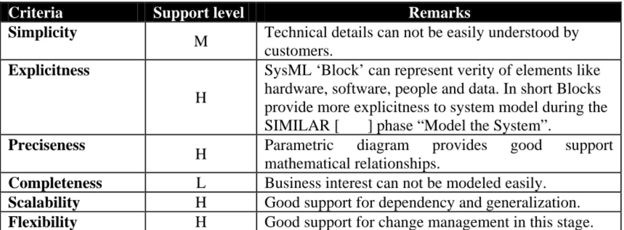
Every SysML diagram represents a model element and it must have diagram frame. Header consist of diagram kind, model element type, model element name and view name/ diagram name in descriptive form [5]. SysML diagrams are divided into four pillars i.e. structure, behavior, requirement, and parametric. Structural pillar provides hierarchical picture of model and gives guideline and regarding application of Block, parts, connectors and ports. Behavioral pillar is comprised of data flows, interactions, activity flow and state machine. This pillar also deals with sequence modeling. Actually these four pillars of SysML make model more consistent and complete and make it possible to observe model from system’s point of view .[6]
The requirement pillar brings new concept of requirement modeling and provide formalism in requirement management activities. Parametric pillar brought lot of expressive power to SysML in depicting mathematical equations because modeling of complex mathematical relations/equation is not an easy task for engineers. SysML also introduced several crosscutting concepts like allocations, flows, traceability of requirements and value binding for mathematical expressions. Further more cross cutting constructs provide good support during integration. Components from different disciplines can be integrated with help of these constructs e.g. mapping of software components to appropriate hardware. [23]
Figure 5. Four Pillars of SysML [18].
3.1
Structure
In SysML system structure is modeled through block definition diagrams (bdd) and internal block diagrams (ibd). A block definition diagram represents system structural hierarchy and classifications of system/components. The internal block diagram tells about the internal structure of a system in terms of its parts, ports, and connectors and package diagram is used to organize the model. [24]
In SysML, Block is basic unit of system structure. Block can be used to represent software, hardware, facilities, personals and other system elements. System structure is presented in the form of block definition and internal block diagrams. Hierarchy of the system/component is described by block definition diagram and internal structure with respect to its parts. Ports and connectors are described by internal block diagram. [24]
The block definition diagram also represents different types of relationships among blocks like dependencies, generalizations, and associations. Actually block definition diagram represent blocks in terms of relationships, properties and operations. It also has good focus on building system hierarchy. As described earlier that structure of system is described in two types of diagrams i.e. block definition diagram and internal block diagram so it is also possible to represent internal structure of Blocks with help of internal block diagram. This diagram represents internal structure of block in terms of its properties and connectors among properties. Simplest form of properties that block can hold are parts and references to other blocks. There is special class of property which specifies different possible interaction among blocks is called port. The role of block will be represented by property, it should be noted that role of block will be defined by keeping view the role of its internal blocks. Concept of SysML blocks is actually drawn from traditional UML Classes with some modifications like complex forms of association have been avoided in SysML. [1, 24, 30]
3.2
Behavior
Behavioral pillar is comprised of activity diagram, use case diagram, sequence diagram and state machine diagram [24]. Actually Behavior diagrams are drawn from UML 2.0 and SysML has made some enhancement in activity diagram whereas sequence, state machine and use case diagram as same as UML 2.0. The flow of controls, inputs and outputs between different actions is described by activity diagrams. It is now possible to develop timelines corresponding to each activity in SysML, where time model is used to represent constraints and time which makes activity diagram more accurate for certain specific scenario. It should be noted that in SysML activities are classes which are connected by associations. [1, 30]
Usage of system is describes by use case diagram. Actors make interaction with system to achieve a their respective goals. Use case represents functionality achieved by the interactions between system and its actors. Actors are connected with use cases by communicational path represented by associations. Use cases are organized in form of packages and also contain dependency between use cases in packages. Some of important relationships in use case diagrams are “include”, “extend”, “generalization”. In short high level description of functionality is described by use-case diagrams. [1]
State machine diagram is used to represent discrete behavior of system by finite state transition systems. There is no difference between UML state machine and SysML state Machine diagrams. State machine describe dynamic behavior of object over time because object pass through different state during its life time. The major objective of state machine is to track these state with respect to corresponding events [21]. In short it can be said that state machine is graph in which nodes are state and arc are transitions. In general state machine is attached to certain class and represent dynamic behavior of its one instance.
Sequence diagram is used to represent flow of control between different parts of system or Actors and system. Sequence diagram represents sending and receiving of messages between interacting entities called lifelines and time is represented by vertical axis. This diagram represents complex interactions. In short we can say that sequence diagram is two-dimensional chart. Messages are represented on horizontal axis and time is represented on vertical axis. [21]
3.3
Requirement
The support of requirement modeling is one of the major advancement made by SysML because as for as UML is concerned there is no explicit support of requirement representation in UML and considered as one of significant shortcoming in UML.[24,1]
SysML provides modeling constructs through which text based requirement can be modeled. In SysML requirement is represented as stereotype of class. A set of stereotyped dependencies is also available in requirement diagram. The “verify dependency” is used to establish link between test case and requirement it verifies. Further more it is also possible to show that model element is refinement of some textual requirement with “refine dependency”. “copy relationship” indicates reuse of requirements in different hierarchies. It is also possible to track derived requirements through derive stereotype. It is always a problem to model whether design elements satisfy requirement or not, SysML solve this difficulty by providing “satisfy dependency”. Requirement diagram also provides containment relationship, this relationship help the designer in decomposing requirement into it’s constitute. [1, 24]
In short requirement diagram gather requirements and builds requirement hierarchies. Different types of relationship will serve as glue to hold requirements together in hierarchies. It is also a good practice to relate important properties like verification with requirements. Actually requirement diagram establishes a bridge between requirement management tool and SysML Models. [1, 24]
3.4
Parametric
Parametric pillar consists of parametric diagrams which is actually a specialized version of internal block diagram. One of major objective of SysML is to solve complex engineering issues and to provide effective solutions.
Parametric diagram in SysML provides a very useful way to model complex mathematical problems. These diagrams are actually used to model the relationship in the form of mathematical or logical expression or constraints which act on the certain set of values. The major element of this diagram is constraint block. Actually constraint block describe a set of parameters and respective constraints on these parameters. The constraints block incorporates constraints such as {F=m*a} and parameters of constraints like F, m and a. Constraint can be reusable because constraints blocks define constraints in generic form i.e. constrains can be applied to several context after their definition. The most important task carry out by these diagrams is to relate the engineering analysis with design models where engineering analysis deals with the different characteristics of the system like performances, reliabilities. Parametric diagram also supports reusability; it is possible to reuse the mathematical equations and logical expression in the SysML. [1, 24]
In short, parametric diagram provide efficient usage of constraints blocks which contain mechanism for engineering analysis. Constraints block binds different constraint parameters. It should be noted that time can be Modeled as a property in Parametric diagram. These diagrams also play an important role in trade-off analysis. [1]
3.5
Cross-Cutting Constructs
Cross-cutting constructs play a significant role in SysML architecture. Actually these construct map one element to another. These constructs may take the form of allocations, requirements, and parametric. Most important cross-cutting construct is allocations which define a basic allocation relationship that will be used to allocate a set
of model elements to another, such as allocation of model elements from behavior to structure constructs or allocating from logical to physical components or from software to hardware.
Figure 6. allocation relationship [18]
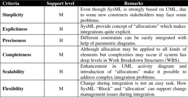
Actually allocation relationship provides an effective way to navigate model by creating cross relationship. Further more it also ensures that various part of model are appropriately integrated. The major concern of cross-cutting constructs is to support activities that will be conducted across the different views, and may be addressed by all or disparate parts of the model. [24, 18]
4
UML
VS
S
YS
ML
In recent time UML has become a de-facto standard of software industry. The language is widely adopted for analyzing and designing software. It is common thinking that UML is software centric and can not be used for system engineering but only suitable for software engineering. However UML has been used for system engineering for many years. [26]
However it should be noted that UML is facing certain challenges relating to system engineering. These challenges include representation of inputs and out puts, continuous systems, physical structures and system characteristics like reliability, safety, performance and parametric relationships. [25]
Further more, it is not appropriate to hold idea that UML and SysML are two separate languages. In fact SysML provides a set of useful extension to UML to support system engineering activities. Although OMG has made several enhancement in UML 2.0 to support system engineering like UML 2.0 has been improved for specifying large and complex architectures and it became easy to decompose complex architectures by applying UML 2.0 structured classifiers, activity diagram partitions is one of major enhancements. The capability of UML 2.0 to integrate structures has been enhanced by cross cutting functionalities. Actually through this functionality model and behaviors are integrated. Further more UML 2.0 also make enhancement in activity diagrams. [25]
No doubt these developments makes UML quite suitable for system engineering but need for certain customize language is always there. For this purpose Systems Engineering Domain Special Interest Group (OMG SE DSIG) [22] and INCOSE[11] work together to customize UML for special needs of system engineers.
Figure7. Comparison of UML and SysML diagrams [26]
Fig.7 shows that UML provide 13 diagrams i.e. for modeling structural views six diagram are allocated and remaining seven diagram are allocated for representing behavioral aspects. Actually SysML customize UML profile, it introduce two new diagram i.e. for modeling real-world constraints SysML provides parametric diagram and requirement diagram for representing requirement and their corresponding attributes. Further more SysML has tailored some of UML diagrams i.e. block diagram actually an enhanced form of UML class diagram. Similarly UML composite structure diagram is modified as internal block diagram. SysML also extended some functionalities of UML activity diagram. [1]
The idea of customization looks good in sense because according to OMG goal of SysML is to provide “standard modeling language for systems engineering to analyze,
specify, design, and verify complex systems, intended to enhance systems quality, improve the ability to exchange systems engineering information amongst tools, and help bridge the semantic gap between systems, software, and other engineering disciplines”. [1, 27]
Actually when scope of modeling activities become wider i.e. from software to system, engineers have to consider all elements of system including hardware, software, data, personnel, procedures, and facilities. To address modeling issues with respect to all system elements customization of UML becomes an important issue for engineers. [1][27]
It should be noted that many system engineers believed that UML is quite efficient and flexible that it can support extensions made by SysML group to make it possible that UML support system engineering activities more efficiently.
Assertion True/False Comment
UML is only suitable for modeling
software systems False
UML has been successfully used for systems engineering and process modeling for many years
SysML and UML are based on the
same key concepts True
These concepts hold true for SysML just as much as for UML
SysML provides systems engineers
with a full set of modeling constructs False
Issues such as timing and deployment are not directly supported by SysML SysML provides useful system
engineering extensions to the UML True
Flow ports, item flows and parametric diagrams are particularly useful extensions
Table 2. Comments Table [26]
Table2. represents relationship between UML and SysML and tries to answer some misapprehension which the people have in their minds.
4.1
Elements Introduced by SysML
The major challenge faced by SysML group at OMG and INCOSE was to make changes in UML 2.0 but they had to make sure that only extremely necessary changes were made. They tried their best to use as much UML as they can. In the beginning lot of changes had been suggested but SysML group recommended following new concepts
4.1.1 Requirements Diagram
Requirements are foundation stone for every system development. In UML there is no direct support of requirement engineering to make-up this deficiency SysML introduced support of requirement engineering in a sense that engineer not only build requirement model but also relate requirement to actual design elements and test procedures. Use case model in UML can only develop an understanding of system but can not help greatly towards traceability of requirements because through use case, requirements are traced to use case only not to design elements. In UML note is used to write comments but it is not considered as model element i.e. designer may exclude these comments from model if they want and there is always a chance that some valuable comments may be lost. To avoid this difficulty SysML requirement diagram provides concept of rational, which is considered as model element. In fact rational provides space for writing comments against requirements, so that it becomes traceable to design element and test case. Rational information actually makes sure that design decisions should also become part of requirement diagram. The rational information may also be helpful for analyzing change impact on requirements. SysML requirement diagram provide a great support for traceability of requirements, and define a trace dependency for this purpose, through this relationship it is possible to relate derived requirements to source requirements. This diagram also play very significant role in solving different complexity problem in requirement, it is possible to decompose requirements through containment relationship just as we can develop containment relationship in UML class diagram. It is always a problem for modeler to link requirement with design elements; this difficulty is by providing satisfaction dependency. It is also possible to relate requirement with associated test cases by means of verification dependency. [31][28]
According to Hause et al [29] one of the strengths of UML is that it is more than just a set of diagrams but there exit an underlying model, which supports the diagrams. In a similar manner requirement diagram also has requirement model behind it. The SysML proposal states “The requirements model describes the SysML support for
describing textual requirements and relating them to the specification, analysis models, design models, etc. A requirement represents the behavior, structure, and other properties that a system, component, or other model element must satisfy”. [29]
However it should be noted that SysML depicts requirement as requirement stereotype of UML class [7].In short, modeling of requirements specifications is very much possible in SysML by keeping in tact different aspects regarding requirements like priority, traceability. In fact only basic features of requirements can be modeled directly, for modeling certain specialized requirements like performance, storage, design constraints designer have to relay on stereotypes.
Notation of requirement diagram in SysML is attached at appendix I [1].
4.1.2 Parametric Diagram
One of the significant advancement made by SysML is inclusion of parametric diagram. Parametric diagram use constraints block as constraints properties. In fact a constraint blocks package expression of constraints. These constraints are packed up in such a way that they can be reusable for other constraints blocks. [1]
Actually through constraints blocks SysML provide mechanism for conducting engineering analysis such as performance and reliability. With the help of constraints block it become possible to establish network of constraints along with their respective mathematical expressions. Parametric diagram also has capability to bind parameters of constraints actually all properties of constraints blocks are defined in term of its parameters. In short we can say that parametric diagram is a restricted form of internal block diagram that represent constraints block along with their respective constraints. The keyword <<constraints>> is used in block definition to show that it is a constraints block. Constraints compartment of block definition will contain expression that specify constraints. However it should be noted that SysML does not provide any particular language for writing Mathematical expressions. [1]
Notation of parametric diagram in SysML is attached at appendix II [1].
4.1.3 Allocations
Concept of allocation is one of new area included by SysML. Actually allocation in SysML is an abstract form of deployment in UML [3]. Actually allocation is a design time relationship between model elements which is used for mapping from source to target. It provides generalized capability to map one element to another. The designer can enforce consistency between different parts of model elements by means of allocations. In SysML allocation is represented by allocate dependency. [4]
In general allocation establishes relation between structure and behavior. Following types of allocations are available in SysML. [1]
4.1.3.1 Behavioral Allocations
Actually behavioral allocations narrate to typical system engineering concept “segregating form from function”. According to this concept there should exist an independent model of function i.e. behavior and form i.e. structure and independent mechanism for mapping. However it should be noted that this concept is not supported by object oriented approach. Although according to system engineering point of view
this seems to be important idea and is very helpful in solving large scale complex problems. [1]
4.1.3.2 Flow Allocation
This type of allocation exclusively maps flows in functional system illustration to flows in structural system depiction. However it should be noted that flow between activities may be control flow or object flow. [1]
4.1.3.3 Structural allocations
For this type of allocation it is necessary to develop two separate representations of system i.e. logical and physical. Engineers should have definite plan for mapping between these two depictions of system. [1]
4.2
Extensions
4.2.1 Activity Diagram
Actually Activity diagram is used to express the flow of controls, inputs and outputs among different actions. SysML provide some useful extensions to UML2.0 activity diagram which is shaped up as SysML activity diagram. Here are some of extensions that made by SysML. [1]
SysML provide three basic concepts for activities i.e. definition, usage and instance. Definition basically deals with description of activities independent of thinking how this activity is used by other activity. Further more SysML also consider how activity is used in context of other activities, this is called usage concept. When it is necessary to consider execution of an activity, it is dealt by SysML concept called instance. [32]
First major enhancement made by SysML is extension of Control in Activity diagram. SysML broaden the concept of control, for starting and disabling of actions which are already executing while controls in UML are only able to start actions. Capability of disabling actions is because SysML indulge controls values as data. In SysML control operator treated control as data and control value is an input or output of control operator. [1]
Further more SysML confine the rate at which entities flow along edges in an activity. This restriction is applied on both types of rates i.e. discrete and continuous. Inclusion of stereotype <<overwrite>> and <<no buffer>> is very significant because these extensions make sure that up to date information is available for actions because old values will not be kept in object nodes. SysML also introduce concept of probabilities in activity diagrams. [1]
Following are some important stereotypes in activity diagrams. 4.2.1.1 Probability:
<<probability>> this is one new concept introduced by SysML and it is applied to activity edges or on the output parameter set and edges have decision nodes or object nodes as sources.[1]
<<probability>> stereotype provide an expression for the probability that the edge will traversed when this stereotype is applied to edges of decision node and object node. It should be noted that when this stereotype is applied to activity edge then this stereotype is become applicable to all other edges coming out of same source. [10] 4.2.1.2 Rate:
<< rate >> number of objects and values for each time interval. When these values or objects will pass from particular edge is specified by rate stereotype. Actually time interval is the rate from which object leaves the source node and reaches to the target
node. Parameter must be streaming for application of this stereotype and rate of parameter must be less than or equal to the rate of edges Matching to parameter. It should be noted that Flow of objects and values may be continuous or discrete. [1] 4.2.1.3 Optional:
The lower multiplicity is zero only when <<optional>> stereotype is applied on parameters. Constraint for this stereotype is that when this stereotype applies to parameters then lower multiplicity must be equal to zero otherwise multiplicity greater than zero, where lower multiplicity zero means that parameter is not required value for activity to begin execution. While the lower multiplicity greater than zero means parameter required value. [1]
4.2.1.4 Continuous:
<< Continuous >> stereotype is actually a special case of rate and it represent as a continuous flow like flow of water. There is no restriction on the flow rate. [1]
4.2.1.5 Discrete:
<<Discrete>> is a special case of <<rate>> stereotype. In discrete rate, time between two items is non-zero. It should be noted that <<Discrete>> and <<continuous>> stereotypes cannot be applied at the same time on same elements [1]. 4.2.1.6 Control Operator:
<<Control Operator>> stereotype is applied both on behavior and operations and is an arbitrarily complex logical operator that can be used to unable and disable actions. It should be noted that when this stereotype is applied to behavior, the behavior then takes control values as input or it may provides control values as output and it treats Control as data. An important consideration in this regard is that when this stereotype is not applied then behavior or operations may not have any parameter typed by control value and if it is applied then behavior or operation must have at least one parameter typed by control value. [1]
4.2.1.7 No Buffer:
This stereotype is applied to object nodes is used to prevent buffer overrun and is used with fast and continuously flowing data values. When the token reach at the out going edges then these edges may refuse to accept and these token may be discarded. <<nobuffer>> stereotype when applied it indicates what happens with token in case of accepting by object node. Token is refused when it arrive at object node in case when stereotype is not applied. [1]
4.2.1.8 Overwrite:
This stereotype is typically used on an input pin. Full object node means that node which holds as many tokens as they allowed by its upper bound. <<overwrite>> stereotype is also applied on object node. As token arrive at full object node it substitute those that are already there. If upper bound is one means it guarantees old data is overridden at an input pin. And if it is greater than one then it would be last according to ordering kind for node. [1].
Notation of Activity diagram in SysML is attached at Appendix V [1].
4.2.2 Block Diagrams
These diagrams are actually providing extension to UML class diagrams. SysML blocks are an enhanced form of UML classes by providing capability of reusability and nesting of connectors. Actually Block is basic unit of structure of SysML and it can represent software, hardware, facilities, personals and other system elements. According
to SysML block diagram concept System structure is presented in the form of block definition and internal block diagrams. Hierarchy of the system/component is described by block definition diagram and internal structure with respect to its parts, ports; connectors are described by internal block diagram. One of important structural feature of block is called property which represents role or usage of its in context of its enclosing block. [1]
4.2.2.1 Labeled compartments
A block in SysML can be partitioned into multiple compartments. Each compartment is to show that what kind of information it can hold. Actually compartments in blocks are used to partition the features. However it should be noted that SysML define some standard compartments. There is no specific order to represent compartment i.e. compartments may be organized in any order [1]. Following are some important compartments in SysML Blocks [1]:-
4.2.2.2 Constraints compartment
This compartment holds one or more constraint imposed on block. The constraint can be written in simple text-based notations or using brace, which is syntax to write constraints in UML. Constraint property also declared within this compartment. The use of constraint is optional i.e. it is totally decision of designer to include this compartment or not.[10]
4.2.2.3 Namespace compartment
This compartment is used to declare namespace of block. A label namespace will appear in definition of block that is defined in namespace of other block. This feature is considered to be useful in a sense that same block may occur several time in same diagram.[1]
4.2.2.4 Structure compartment
Structure compartment will represent connector and other internal structural elements. A label structure is used to show this compartment. As block can appear several times in same diagram, so it is necessary to represent this compartment separately. Normally this compartment constrains graphical elements so wider compartment is required for structure. [1]
4.2.3 Ports and Flows
According to OMG SysML specifications port is defined as “A port is an
interaction point between a block or part and its environment that is connected with other ports via connectors”. [1]
Port provides the block, capability of interaction with its environments or to other blocks. One of advantages to have port on block is make block reusable, and to have definite and independent mechanism for communication among blocks. It should be noted that block can own its port; therefore port can be considered as part of block definition. [1]
Following types of ports are provided by SysML. [1] 4.2.3.1 Standard Ports
Standard ports having a very simple concept of communication i.e. it provides services of blocks to environment as well as if block requires some thing from environment then standard port come in to play. Concept of standard port is very useful for service oriented architecture and peer-to-peer communications where it is much need to have bi-directional flow of data. [1]
4.2.3.2 Flow Ports
Actually flow port is used to specify the input and output that can enter and leave blocks. In geranial flow port are for asynchronous communication. In short we can that flow port is used to represent item that can flow between block and its environment.[1] 4.2.3.3 Item Flows
Important distinctions between flow ports and item flows is that flow port specifies what can flow in and out of blocks where as item flows specify what does flow among blocks/or part and their respective associations.[1]
Notations of block diagram in SysML is attached at appendix III, IV [1]. 4.2.3.4 Outcome
It has been observed that SysML is not a new language but it is only customization of UML to make it favorable for system engineering activities. SysML group at OMG tried it best to conduct only modification in UML which is entirely necessary and tried to retain maximum elements of UML in SysML.
SysML retain state machine, interaction and use case from UML 2.0 with out any modifications where as activity diagram and block diagram in SysML are enhanced version of activity diagram and composite structure diagram of UML 2.0.[33]
However it should be noted that in UML 2.0 Interactions are supported by four diagrams names; sequence diagram, communication diagram, interaction overview diagram and timing diagram. SysML only includes sequence diagram and excludes other three. [1]
It has been aim of SysML designers to keep language as simple as they can for this several complex form of UML relationships are avoided in SysML, like n-ary association and qualified association are excluded from SysML. Navigation is also simplified by removing arrowheads on both ends, how ever it should be noted that in case of unidirectional association SysML also have arrow heads as UML. Generalization relationship between associations is also dropped from SysML. All these efforts have been made to make language as simple as possible.[1]
![Figure 2. Relationship between UML and SysML. [1]](https://thumb-eu.123doks.com/thumbv2/5dokorg/5428058.139932/20.892.267.687.370.647/figure-relationship-uml-sysml.webp)
![Figure 9. Requirement Diagram for RSW [33]](https://thumb-eu.123doks.com/thumbv2/5dokorg/5428058.139932/40.892.176.765.90.807/figure-requirement-diagram-for-rsw.webp)
![Figure 10. Parametric models for windshield [33]](https://thumb-eu.123doks.com/thumbv2/5dokorg/5428058.139932/42.892.181.729.103.736/figure-parametric-models-for-windshield.webp)
![Figure 11. RSW Block Definition Diagram [33]](https://thumb-eu.123doks.com/thumbv2/5dokorg/5428058.139932/45.892.167.809.83.1045/figure-rsw-block-definition-diagram.webp)
![Figure 14.Ports and Interfaces [33]](https://thumb-eu.123doks.com/thumbv2/5dokorg/5428058.139932/49.892.197.695.136.1035/figure-ports-and-interfaces.webp)
![Figure 15. Test case for RSW [33]](https://thumb-eu.123doks.com/thumbv2/5dokorg/5428058.139932/51.892.238.765.360.787/figure-test-case-for-rsw.webp)
![Figure 16.Constraints Blocks for RSW [33]](https://thumb-eu.123doks.com/thumbv2/5dokorg/5428058.139932/53.892.191.734.113.865/figure-constraints-blocks-for-rsw.webp)
![Figure 17. Parametric diagram for RSW [33]](https://thumb-eu.123doks.com/thumbv2/5dokorg/5428058.139932/54.892.235.742.184.741/figure-parametric-diagram-for-rsw.webp)
