Mälardalen University Press Licentiate Theses No. 222
EVALUATION OF A MODULAR THERMALLY DRIVEN HEAT
PUMP FOR SOLAR HEATING AND COOLING APPLICATIONS
Corey Blackman 2015
School of Business, Society and Engineering
Mälardalen University Press Licentiate Theses
No. 222
EVALUATION OF A MODULAR THERMALLY DRIVEN HEAT
PUMP FOR SOLAR HEATING AND COOLING APPLICATIONS
Corey Blackman
2015
Copyright © Corey Blackman, 2015 ISBN 978-91-7485-240-0
ISSN 1651-9256
Everything should be made as simple as possible, but no simpler.
Acknowledgments
My family, mother and father for their unwavering support, sacrifice and formative lessons. The source of my pragmatism and determination.
My best friends who helped me make the decision to move forward with this level of study and provided sustenance every step of the way thus far. B Franssen for immeasurable support with and beyond the compilation of this and other documents. Motivation, unobtrusive and assertive daily encourage-ment and endorseencourage-ment. Without whom many publications would have been ‘non-starters’ or ‘non-finishers’.
My supervisor Dr. Chris Bales for support, understanding and motivation in my march towards doctoral qualification. Without whom I probably would not have embarked on this journey of learning in an area which is so important and interesting to me.
My supervisor Dr. Eva Thorin for competent organisation, support and quality control in this process.
Göran Bolin for optimistic, inciting and challenging mentorship.
Anneli Wadeborn for proof reading of this thesis and all foundation publica-tions, pragmatic motivation and excellent stewardship of the LIFE project. Employees of ClimateWell AB and Löfbergs Lila for flexibility, understand-ing and assistance beyond the typical call of duty.
The doctoral students and leadership of the REESBE PhD School for thought provoking and prolific discussions.
My professors from the Universidad de Oriente for the foundation of knowledge upon which all my subsequent achievements have been based.
This thesis is based on work conducted within the industrial post-graduate school REESBE – Resource-Efficient Energy Systems in the Built Environ-ment. The projects in Reesbe are aimed at key issues in the interface be-tween the business responsibilities of different actors in order to find com-mon solutions for improving energy efficiency that are resource-efficient in terms of primary energy and low environmental impact.
The research groups that participate are Energy Systems at the University of Gävle, Energy and Environmental Technology at the Mälardalen Univer-sity, and Energy and Environmental Technology at the Dalarna University. Reesbe is an effort in close co-operation with the industry in the three regions of Gävleborg, Dalarna, and Mälardalen, and is funded by the Knowledge Foundation (KK-stiftelsen).
Summary
The building sector accounts for 40% of primary energy consumption within the European Union, therefore reducing this energy consumption is critical in decreasing total energy usage. Given that the majority of energy use within the built environment is for space conditioning and domestic hot water prepa-ration it is prudent to decrease primary energy used for these end purposes in order to have the biggest overall environmental impact. Using solar energy technology for both heating and cooling has the potential of meeting an ap-preciable portion of the energy demands in buildings throughout the year. By developing an integrated, multi-purpose system, that can be exploited all twelve months of the year, a high utilisation factor can be achieved which translates to more economical systems. However, in spite of favourable energy saving prospects, solar heating and cooling technology is still somewhat un-derutilised, due to its high initial costs, and lack of knowledge of system im-plementation and expected performance. For improved cost effectiveness and thus widespread uptake of solar heating and cooling systems, the market calls for standardised, plug-and-function, small and medium sized solar heating and cooling kits.
The central premise of this thesis is that with a modular thermally (i.e. sorption) driven heat pump that can be integrated directly into a solar thermal collector, cost-effective pre-engineered solar heating and cooling system kits can be developed. This thesis thus aims to describe the performance charac-teristics of sorption integrated collectors and their energy and cost saving po-tential when implemented as a sorption integrated collector solar heating and cooling system (SISHCS).
Evaluations of individual sorption modules were carried out where the principle performance characteristics of cooling and heating power and energy delivery as well as solar energy to cooling conversion efficiencies were inves-tigated. Further experimental evaluations were carried out to characterise the performance of solar thermal collectors with integrated sorption modules in an outdoor laboratory setting. Sorption integrated collector performance was studied under steady state temperature conditions where various key perfor-mance parameters were also identified. Similarly, experimental studies on a full SISHCS were performed. Operation of the full system was completely autonomous and dynamic providing performance data under varying temper-ature and solar insolation conditions.
Results showed that individual sorption modules delivered cooling for 6 hours at a power of 40 W and temperature lift of 21°C. Upon integration of the sorption modules into a solar collector, solar energy to cooling energy con-version efficiencies (solar cooling COP) were between 0.10 and 0.25 with av-erage cooling powers between 90 and 200 W/m2 collector aperture area.
Whilst further investigations of the SISHCS yielded electrical cooling COP ranging from 1.7 to 12.6 with an average of 10.6 for the test period.
Additionally, simulations were performed to determine system energy and cost saving potential for various system sizes over a full year of operation for a 140 m2 single-family dwelling located in Madrid, Spain. Simulations yielded
an annual solar fraction of 42% and potential cost savings of €386 per annum for a solar heating and cooling installation employing 20 m2 of sorption
inte-grated collectors.
The studies found that further opportunities exist for optimisation of the individual sorption modules by adjusting their salt and water contents and for the SISHCS by implementing better control strategies. On average, more than 50% of the thermal energy from the collectors is ejected as waste heat to the environment. Therefore, finding applications that could exploit even some of this otherwise wasted output could have a significant impact on overall eco-nomic viability of the SISHCS.
Sammanfattning
Byggnader står för omkring 40 % av den primära energianvändningen i EU varför energibesparing inom detta område är ytterst väsentligt för att minska den totala energianvändningen. Med tanke på att merparten av energianvändningen i byggnader är för uppvärmning, kyla och varmvattenberedning, är det rimligt att minska energiåtgången för dessa ändamål för att uppnå maximal total effektivitet. Användande av solenergiteknik för både uppvärmning och kyla har potentialen att tillhandahålla en väsentlig del av energibehovet i byggnader året om. Genom att utveckla ett integrerat flerfunktionssystem som kan utnyttjas under årets alla tolv månader, kan en hög utnyttjandefaktor uppnås vilket innebär mer ekonomiska system. Trots gynnsamma energibesparingsmöjligheter är solvärme- och kylteknik fortfarande underutnyttjade på grund av höga initialkostnader och bristande kunskap om systemimplementering och förväntade resultat. För förbättrad kostnadseffektivitet och därmed bredare användning av solvärme- och kylsystem efterfrågar marknaden små och medelstora standardiserade, ”plug-and-function”, solvärme- och kylsystempaket.
Den centrala tanken bakom denna avhandling är att med en modulär värmedriven (dvs sorptionsdriven) värmepump som kan integreras direkt i en solfångare, kan man utveckla kostnadseffektiva förkonstruerade solvärme- och kylsystempaket. Denna avhandling syftar således till att beskriva sorptionsintegrerade solfångares egenskaper och energi- och kostnadsbesparande potential när de används i ett sorptionsintegrerat solvärme och kylsystem (SISHCS).
Utvärderingar av enskilda sorptionsmoduler genomfördes där karakteristiken för prestanda hos kyl- och värmeeffekt och energileverans samt verkningsgraden för omvandling från solenergi till kyla undersöktes. Ytterligare experimentella utvärderingar för att karakterisera prestandan hos solfångare med integrerade sorptionsmoduler utfördes i utomhuslaboratoriemiljö. Prestanda för solfångare med integrerade sorptionsmoduler studerades vid stationära temperaturförhållanden där olika nyckeltal också identifierades. På samma sätt utfördes experimentella studier av ett fullständigt SISHCS. Driften av hela systemet var helt självstyrande och dynamiskt vilket gav prestandadata för varierande temperatur- och solinstrålningsbetingelser.
Resultaten visade att de enskilda sorptionsmodulerna levererade kyla under 6 timmar med en effekt av 40 W och temperaturlyft på 21°C. Vid integrering av sorptionsmodulerna i en solfångare, var verkningsgraden för omvandling från solenergi till kylenergi (solkyla COP) mellan 0,10 och 0,25 med ett genomsnittligt kyleffektindex mellan 90 och 200 W/m2 solfångaraperturyta.
Medan ytterligare undersökningar av SISHCS gav el-kyla COP mellan 1,7 - 12,6 med ett medelvärde på 10,6 under testperioden.
Dessutom har simuleringar av systemenergi- och kostnadsbesparingspotentialer under ett år utförts för olika systemstorlekar för ett 140 m2 enfamiljshus i Madrid, Spanien. Simuleringarna gav en årlig andel
solenergi på 42% och potentiella kostnadsbesparingar på 386 € per år för en 20 m2 sorptionsintegrerad solvärme-och kylanläggning (SISHCS).
Studierna visade att ytterligare möjligheter finns för optimering av de enskilda sorptionsmodulerna genom att justera salt- och vattenmängder och för SISHCS genom bättre kontrollstrategier. I genomsnitt avges mer än 50% av värmeenergin från solfångarna som spillvärme till omgivningen. Om man kan hitta tillämpningar som kan utnyttja även en del av denna förlustenergi kan det därför ha en betydande inverkan på den totala ekonomiska bärkraften för SISHCS.
List of papers
This licentiate thesis is based on the following papers:
I. Blackman, C. & Bales, C., 2015. Experimental Evaluation of a Novel Ab-sorption Heat Pump Module for Solar Cooling Applications, Science and
Technology for the Built Environment, 21(3), pp.323–331.
II. Blackman, C., Hallström O. & Bales, C., Demonstration of Solar Heating and Cooling System using Sorption Integrated Solar Thermal Collectors,
EuroSun Conference Proceedings, 2014.
III. Blackman, C., Bales, C. & Thorin, E., 2015. Techno-economic Evaluation of Solar-assisted Heating and Cooling Systems with Sorption Module In-tegrated Solar Collectors, Energy Procedia, 70, pp.409–417.
Author’s Contribution
Publications included in the licentiate thesis.
I. Corey Blackman planned, prepared for and carried out the tests. Corey Blackman analysed the test results along with Dr. Chris Bales. Corey Blackman did all the writing for the article with support from Dr Chris Bales.
II. Corey Blackman planned, prepared for and executed the collector tests. Corey Blackman and Olof Hallström carried out the monitoring of the large-scale installation. Olof Hallström prepared the data and wrote the results of the monitoring for the large-scale installation. Corey Blackman, Olof Hallström and Dr. Chris Bales did the evaluation of the results. Corey Blackman did most of the writing for the paper.
III. Corey Blackman planned the simulations along with Dr. Chris Bales. Co-rey Blackman carried out the simulations and wrote all of the paper. Eval-uation of the results was a collaborative effort between Corey Blackman, Dr. Chris Bales and Dr. Eva Thorin.
Contents
1 INTRODUCTION ... 1
1.1 Background ... 1
1.2 Objectives and Scope ... 4
1.3 Overall Research Methodology ... 5
1.4 Structure of Thesis ... 6
2 THEORETICAL BACKGROUND ... 8
2.1 Solar Domestic Hot Water (DHW) Systems ... 8
2.2 Solar Space Heating ... 8
2.3 Solar Thermal Collectors ... 9
2.4 Solar Space Cooling Systems ... 10
2.4.1 Thermally Driven Cooling ... 10
2.4.2 Electrically Driven Cooling ... 12
2.4.3 Combined Solar Heating and Cooling Systems ... 12
2.5 Performance Indicators – Solar Heating and Cooling Systems ... 14
3 THE SORPTION HEAT PUMP MODULE ... 17
3.1 Sorption Process Description ... 17
3.2 Triple-State Thermochemical Storage Cycle ... 17
3.3 Sorption Heat Pump Module Characteristics... 19
3.4 Sorption Modules in Combined Solar Heating and Cooling Systems 22 3.5 Sorption Integrated Collectors ... 22
3.5.1 Liquid Based Collectors ... 23
3.5.2 Air-Based Collectors ... 24
3.6 Sorption Integrated Collector System Operation ... 26
3.7 Absorption chiller integration of the sorption module ... 27
4 EXPERIMENTAL EVALUATIONS &SIMULATION ... 28
4.1 Individual Sorption Module Tests ... 28
4.1.1 Sorption Module Prototypes ... 28
4.1.2 Test Methodology – Sorption Modules ... 28
4.1.3 Desorption Mode ... 30
4.1.4 Absorption Mode ... 31
4.1.5 Test Sequences ... 31
4.2 Sorption Collector Tests ... 32
4.2.1 Sorption integrated collector prototypes ... 32
4.3 Combined Solar Heating and Cooling System Evaluation ... 34
4.3.1 Operation and Control – Sorption Integrated Collector Heating & Cooling System ... 36
4.4 Simulation of Sorption Integrated Solar Heating and Cooling Systems ... 37
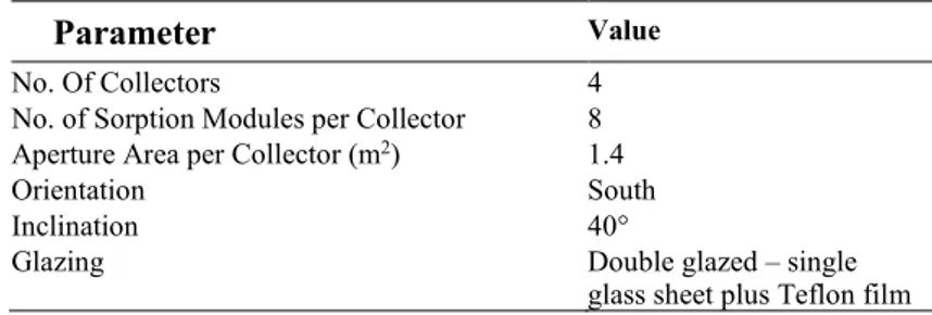
4.4.1 Reference System ... 37
4.4.2 Simulation Tools ... 42
4.4.3 Simulation Methodology ... 42
4.4.4 Model Limitations ... 43
5 RESULTS AND DISCUSSION ... 44
5.1 Performance indicators ... 44
5.2 Individual Sorption Modules ... 46
5.3 Sorption Integrated Collectors ... 51
5.4 Sorption Integrated Solar Heating & Cooling System ... 55
5.5 Simulations ... 58
5.5.1 Economic Analysis ... 60
5.5.2 Energy Price Sensitivity Analysis ... 61
6 CONCLUSIONS ... 63
7 FUTURE WORK ... 65
REFERENCES ... 66
List of figures
Figure 1: Research study progression ... 5 Figure 2: Illustration of different space cooling distribution systems [23] 12 Figure 3: Conceptual example of summer and winter operations of a
combined solar heating and cooling system [7] ... 13 Figure 4: Pressure vs temperature phase diagram depicting the triple-state
process [31] ... 18 Figure 5: Heat Storage Energy Densities of Various Energy Storage Media
(Three-phase absorption: cycle with triple-state crystallisation process. Three-phase sorption: cycle with triple-state
crystallisation and dehydration) [31] ... 19 Figure 6: Sorption module operation – thermal energy and temperature
levels in desorption and absorption phases... 21 Figure 7: Sorption module integration in a flat plate solar thermal
collector ... 22 Figure 8: Evacuated tube sorption integrated solar thermal collector ... 24 Figure 9: Air-based sorption integrated collector for roof mounting ... 25 Figure 10: Air-based sorption integrated collector integrated into a facade 25 Figure 11: Concept for absorption chiller integrated sorption modules.
Sorption modules (grey) covered by heat exchange flanges (white) interconnected by pipes for heat transfer fluid (orange) 27 Figure 12: Sorption module prototype with heat exchangers ... 29 Figure 13: Test set up for sorption module evaluation in the solar simulator
test rig ... 30 Figure 14: Hydraulic schematic of individual sorption module test set up .. 30 Figure 15: Hydraulic schematic of outdoor collector laboratory test set
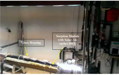
up. ... 33 Figure 16: Photograph of outdoor laboratory sorption collector test
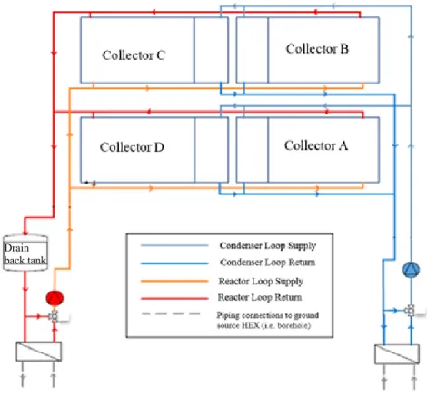
instalation ... 34 Figure 17: Schematic of full sorption integrated collector solar heating and
cooling system ... 35 Figure 18: Photograph of the full sorption integrated solar heating and
Figure 19: Schematic of reference system ... 38 Figure 20: System 1 schematic ... 39 Figure 21: System 2 schematic ... 40 Figure 22: System 3 schematic (top). Hybrid PV- sorption integrated
collector concept (bottom) ... 41 Figure 23: Pictorial representation of the system simulation and analysis
process ... 43 Figure 24: Typical cycle showing temperature evolution for desorption and
absorption phases for Module B at 100% desorption and 21°C temperature lift (Trxo – outlet fluid temperature from reactor heat exchanger, Trxi – inlet fluid temperature to reactor heat exchanger, Tcxo – outlet fluid temperature from
condenser/evaporator heat exchanger, Tcxi – inlet fluid
temperature to condenser/evaporator heat exchanger, Tr – reactor surface temperature) ... 47 Figure 25: Typical cycle showing areas of interest for determining the
performance indicators for desorption and absorption phases for Module B at 100% desorption and 21°C temperature lift. ... 48 Figure 26: Graph of average cooling power versus temperature lift with
characteristic equations for Module A (lower) and Module B (upper) ... 49 Figure 27: Sorption collector performance test results for re-cooling
temperature 20°C during absorption (Ehs-ce- re-cooling energy dissipated during desorption, Ehs-re - re-cooling energy
dissipated during absorption, EDHW- thermal energy recovered during swap mode that could be used for DHW purposes, Ecool – cooling energy delivered during absorption) ... 52 Figure 28: Sorption collector performance test results for re-cooling
temperature 30°C during absorption (Ehs-ce- re-cooling energy dissipated during desorption, Ehs-re - re-cooling energy
dissipated during absorption, EDHW- thermal energy recovered during swap mode that could be used for DHW purposes, Ecool – cooling energy delivered during absorption) ... 52 Figure 29: Graph depicting how state of charge of the sorption modules
corresponds to the solar insolation ... 53 Figure 30: Performance measurement results for system test with sorption
integrated collectors (Ehs-ce- re-cooling energy dissipated during desorption, Ehs-re - re-cooling energy dissipated during
absorption, EDHW- thermal energy recovered during swap mode that could be used for DHW purposes, Ecool – cooling
energy delivered during absorption, Eel – daily electrical input for running of the system) ... 55 Figure 31: Annual thermal energy demand based on the reference system
and total annual energy savings for each system type and size simulated. ... 59 Figure 32: Solar fraction of simulated systems ... 60 Figure 33: Energy cost savings based on the average and ±15% variation of
natural gas (left) or electricity prices (right) according to system size. ... 61
List of tables
Table 1: Test sequences carried out for each module type ... 31 Table 2: Main characteristics of outdoor laboratory installation in sorption collector tests. ... 32 Table 3: Main characteristics of sorption collector in system evaluation . 35 Table 4: Sorption module performance results with respect to desorption
level with colour code - highest value per row (dark green) to lowest value (yellow). ... 50 Table 5: Key performance indicators of the sorption integrated collectors
in outdoor tests. ... 54 Table 6: Key performance indicators of the sorption integrated collector
system tests ... 56 Table 7: Summary of key performance data from other experimental and
pilot project evaluations of SHCS ... 57 Table 8: Annual energy cost savings ... 60
List of principal symbols and acronyms
AC Alternating current C/E Condenser/Evaporator
COPel Electrical coefficient of performance COPsolar Solar coefficient of performance
CPC Compound parabolic solar thermal collector DC Direct current
DHW Domestic hot water
Echill Cooling energy during absorption phase (individual sorption mod-ules) (Wh)
Ecool Cooling energy during absorption phase (kWh) EDHW Heating energy delivered to domestic hot water (kWh) Eel Electrical energy consumed by the installation (kWh) Eheat Heating energy during absorption phase (Wh)
Ere-cool Heating energy during desorption phase (condensation energy dis-sipated) (Wh)
ETC Evacuated tube solar thermal collector FPC Flat plat solar thermal collector HEX Heat exchanger
HVAC Heating ventilation and air conditioning PCM Phase change material
PVT Hybrid solar photovoltaic and thermal collector Qchill Average cooling power during absorption phase (W) Qcool Average cooling power during absorption phase (W) Qheat Average heating power during absorption phase (W)
Qre-cool Average heating power during desorption phase (condensation power dissipated) (W)
SHCS (Combined) Solar heating and cooling system SIC Sorption (module) integrated collector
SISHCS Sorption integrated collector solar heating and cooling system Tabs Absorption temperature (°C)
Tcond Condensation temperature (°C)
Tcxi Average inlet temperature to condenser/evaporator heat exchanger (°C)
Tcxo Average outlet temperature from condenser/evaporator heat ex-changer (°C)
Tevap Evaporation temperature (°C)
Tr Average surface temperature of reactor and absorber (°C) Trxi Average inlet temperature to reactor heat exchanger (°C) Trxo Average outlet temperature from reactor heat exchanger (°C)
Greek symbols
ΔTlift Average temperature lift (°C) ƞtotal Total Efficiency
1 Introduction
1.1 Background
Many homes and most commercial and industrial facilities would be rather uncomfortable most of the year without some form of indoor climate control. In the built environment, a substantial percentage of energy use is thus geared towards keeping us comfortable year round within our wooden, steel or con-crete cocoons. Our buildings protect us from the ever more frequent harshness and temperature extremes of nature allowing for improved health and produc-tivity. A positive shift has come in improving building façades, insulation and general building planning as more governments and organisations take heed of climate change warnings.
Reducing indoor comfort energy requirements for the entire year, incor-porating both heating and cooling requirements is of paramount importance. Employing technologies that consider both energetic and exergetic efficiency, which use environmentally benign substances and materials, that are easily maintained, have good technical longevity and are economically viable, is key to sustainability within the built environment.
This has seen an increasing number of policies geared towards generating the impetus necessary to transition towards fossil-fuel free energy sources be-ing put in place [1]. Whilst adherbe-ing to typical open market forces, it is un-likely that many companies would move in the direction of increasing renew-able energy share in the built environment. This has been manifested as a ra-ther slow, tentative march towards investing in sustainable energy technolo-gies, a pace that due to the gravity of environmental issues, has been seen as too ‘lethargic’. With distant payback periods and difficulty to recoup all ben-efits within typical 5 to 10 year investment windows, private companies hesi-tate to make the investments necessary to deploy renewable energy technolo-gies. Fortunately, many of the policies needed to achieve the increasing effi-ciency and expanding renewable energy goals are consistent with programmes needed to encourage innovation and productivity growth throughout the econ-omy [2].
In the field of heating, ventilation and air conditioning (HVAC), climate control units for heating and cooling contribute substantially to CO2
emis-sions. For example, in Spain, heating accounts for 42% of the country’s energy consumption in homes [3]. The European average stands at 57% of building energy use going towards heating [4]. While yearly electricity consumption
for air conditioning units can be quite significant the closer to the equator one comes, however, arguably the more alarming effect of air conditioner use is its influence on electricity demand. Air conditioning units can place signifi-cant strain on the electricity grid due to the fact that they are generally all operating at the same time. In the summer months, demand often peaks rapidly between 15:00 and 18:00 [3].
The European Union directive for the promotion of the use of energy from renewable sources seeks to establish binding objectives where 20% of the gross end consumption of energy should be provided by renewable sources by 2020 [1]. The aim within construction is for the erection of low or ‘zero-en-ergy buildings’ in all new constructions also by 2020. Within the policy all public buildings constructed after that year would generate as much energy as they consume. Within this field of thought, a plausible roadmap for zero en-ergy buildings has been suggested where these enen-ergy self-sufficient buildings could be developed by [5]:
Reduction of energy demand.
Efficient energy conversion chains (i.e. minimisation of exergy losses).
Covering of remaining energy demand employing renewable energy. Even though policy for new buildings is a critical step in the right direc-tion, in order to make a dent in the current energy consumption tendency, the retrofitting of buildings towards ‘zero energy’ is also necessary. Given its ubiquity and abundance, solar energy is poised to be a key renewable energy source for the built environment.
Solar energy has long been known to be valuable for both passive and active heating of buildings along with the preparation of domestic hot water (DHW). Currently, due to relatively low capital costs, solar thermal energy systems are economical in places such as China, the Middle East and South Africa, however these costs still need to decrease by 30% to as much as 80% to be economically competitive compared to gas-fired boilers in the USA. In Europe, heat from solar energy sources needs to become 50% cheaper by 2020 to reach fossil fuel cost parity [6]. Potential cost savers have been cited as the use of cheaper materials, integration with heat pumps and passive solar ther-mal heating system that eliminate pumps and controls [6]. An additional pos-sibility is to extend the utility of solar energy systems to include cooling as well as heating at marginal or no incremental cost compared to today’s sys-tems to offer higher energy savings [7].
Using energy from the sun for heating and cooling is seen as quite bene-ficial for primary energy savings. Solar thermal technology for both heating and cooling is capable of providing an appreciable portion of the energy re-quirements for space conditioning in buildings [8,9]. In Europe, small capacity
air conditioning systems (i.e. systems up to 12kW) are set to quadruple in pri-mary energy consumption in 2020 compared to the levels in 1996. This rise is mainly due to improvements in living standards and the architectural charac-teristics and trends such as increasing insulation [10]. Currently, most com-mercial absorption chillers are of large capacity and are most commonly LiBr-water chillers and not suitable for the domestic or small commercial markets. These installations also require cooling towers which add cost and complexity to the system [11]. In many cases, high upfront costs of solar driven cooling systems compared to standard compressor driven cooling systems may be con-sidered the principal obstacle for the widespread uptake of small and medium scale solar thermal cooling systems. Furthermore, market penetration for these heat driven chillers has been hampered by not only cost, but also technical limitations as well as reliability concerns due to component corrosion, crys-tallisation issues, performance limitations due to narrow working concentra-tion ranges and leakage of vacuum shells [11,12]. Addiconcentra-tionally, in most cases, specialised knowledge and understanding of the technology is necessary for installation, commissioning and operation to be carried out effectively, lead-ing to a general unattractiveness of these solar thermal coollead-ing installations [10].
According to the report on ‘Strategic Research Priorities for Solar Ther-mal Technology’[13], strategic R&D requirements for increased market pen-etration of solar thermal cooling by 2020 should provide for small and me-dium-sized solar thermal cooling kits with plug-and-play functionality. Fur-thermore, high integration of systems for space cooling, heating and hot water would increase year round usage and therefore reduce overall system payback time. Improved controllers and hydraulic concepts leading to electrical coef-ficient of performance (COPel) greater than 10 as well as improved cost-per-formance relations are all seen as necessities to future growth of the solar heat-ing and coolheat-ing sector [13]. For solar thermal coolheat-ing cycles to penetrate the market, their performance has to improve to a level that can compete with the traditional vapour compression systems. This is mainly dependent on the COPel of the system, since the principle benefit of a solar cooling installation is to reduce electricity usage compared to conventional cooling equipment. Most current solar thermal cooling demonstration installations exhibit COPel between 3 and 7 which, when factoring in the higher installation costs, make them economically uncompetitive with vapour compression systems which have COPel in a similar range [14]. This is intrinsically coupled to system complexity where pumps, fans, valves and other electrical devices should be kept to a minimum and consume as little electrical energy as possible (i.e. low parasitic power demand). System complexity, effective control and efficiency are all trade-offs [8,9].
Another fast growing area for solar heating and cooling systems is in the coupling of solar photovoltaic (PV) systems with conventional vapour com-pression air conditioning systems and heat pumps. With the precipitous drop
in the prices of solar PV this provides great opportunity for solar electric sys-tems to drive electric heating and/cooling units in a cost effective way [15]. This is therefore an increasingly popular area of research that could also lead to more renewable energy use in the built environment.
A vision for the future of an efficient and cost effective alternative for conventional heating and air conditioning systems that can be employed in large and small applications is an intriguing one. Proliferation of solar heating and cooling technologies could bestow both developed and developing nations with tools to combat current environmental issues while promoting energy in-dependence in the built environment.
Presented in this study is a novel sorption module developed in order to address the aforementioned market penetration limitations of solar thermal cooling systems; namely system size and cost, as well as, technical complexity limitations. The module has been developed for direct integration into a solar thermal collector. With this sorption module integrated solar thermal collec-tor, a completely modular solar heating and cooling system, installed with standardised components in a highly integrated fashion, can be developed. By studying and understanding module performance and limitations, the intercon-nection of the individual sorption modules (and collectors) installations of any capacity could be developed. These pre-engineered systems could then be im-plemented with reduced complexity and reduced need for highly specialised competencies compared to existing solar cooling technologies. The modules may use a dry cooler as a heat sink obviating the need for a cooling tower which in turn reduces system complexity, cost and maintenance requirements [9].
1.2 Objectives and Scope
The central premise of this work is that with a sorption heat pump module that can be integrated directly into a solar thermal collector, cost-effective pre-en-gineered solar heating and cooling system kits can be developed. The first objective of this thesis was to study the performance of sorption integrated collectors and their implementation in solar heating and cooling systems. The second objective was to investigate the energy and cost saving potential of the sorption integrated solar heating and cooling system.
The specific research questions were:
What are the primary performance indicators for a sorption integrated solar heating and cooling system?
What are the typical values of the performance indicators for a sorp-tion integrated solar heating and cooling system?
What are the potential energy and monetary savings of the system?
The studies cover experimental evaluation of the sorption modules on an individual level in the laboratory and define key performance figures. Further performance studies were carried out at a collector level and subsequently at the systems level via outdoor evaluations. Simulations were based in part on the empirical data from these studies. The studies in the context of this thesis did not include development of test methodology for the sorption module or the simulation models. Studies were primarily focused on analysis of the test and simulation results.
1.3 Overall Research Methodology
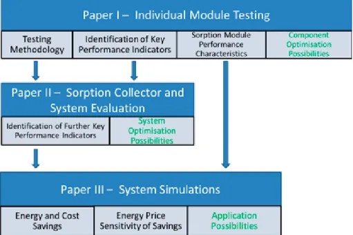
The studies summarised in this thesis were structured and planned to allow for cohesive building on the findings of each study (see Figure 1). The foundation study performed in Paper I sought to evaluate the individual sorption module, its key performance parameters and performance characteristics. Further per-formance evaluations and indicators for sorption collectors and full system evaluations were carried out in Paper II. Paper III then built on information from both Papers I and II as input for a full system simulation for techno-economic analysis of the sorption integrated collector solar heating and cool-ing system.
Each of the papers also provided the researchers with valuable information (shown in green in Figure 1) on various component and system optimisation possibilities, and additionally, insight into the most prolific applications for the studied solar heating and cooling system. These learning outcomes were used to develop the possible scope of continued future research.
1.4 Structure of Thesis
The thesis report is based on studies carried out in three scientific papers.
Chapter 1: Introduction
In this chapter a general background is given on the topic of the thesis, objectives, scope and overall methodology.
Chapter 2: Theoretical Background
This chapter provides a basic introduction to solar heating and cooling technology
Chapter 3: The Sorption Heat Pump Module
The sorption heat pump module is defined and a description of the sorption process that forms the foundation of the operation of the sorption module is given in this chapter. This then segues into the main operating principle of the sorption module and subsequently various concepts of sorption module integration into solar heating and cooling systems.
Chapter 4: Experimental Evaluation and Simulation
This fourth chapter chronicles the experimental evaluation of indi-vidual sorption modules, sorption collectors and full sorption inte-grated collector heating and cooling system. Includes is also the methodology used for solar heating and cooling systems simula-tions for a residential building application.
Chapter 5: Result and Discussion
This chapter presents the results of the experimental evaluations and discusses the key performance indicators of the modules, col-lector and system. This chapter also includes the findings of system simulations with expected energy and cost savings for different system sizes of installations located in Madrid, Spain.
Chapter 6: Conclusions
This penultimate chapter draws conclusions based on the studies carried out.
Chapter 7: Future Work
2 Theoretical Background
Dating back to the time of the Romans, solar energy has been used for the passive heating of buildings by trapping heat behind glazed façades [16]. The active use of solar energy for heating is currently recognised as a viable way to have precise control over our indoor environment while reaping the envi-ronmental benefits of utilising energy from the sun instead of fossil fuel de-rived forms of energy. Solar energy can also be extended beyond applications of just heating to also include cooling applications. This versatility gives rise to the possibility of using solar energy year round, that is, during the winter for space heating, during the summer for space cooling and throughout the entire year for DHW preparation. By developing systems that can be exploited all twelve months of the year a very high utilisation factor can be achieved which translates to more economical systems. That is, for the same system size and price a higher percentage of useable energy can be generated and thus high levels of energy savings [17].
2.1 Solar Domestic Hot Water (DHW) Systems
Solar thermal energy systems for the production of domestic hot water may be considered to be the most mature out of all solar energy technologies [18]. Employed commercially from the early 1900s solar DHW systems have been implemented across the globe. Solar DHW system may even be the principal water heating apparatus for dwellings in countries such as Israel, Barbados, Cyprus, and Greece, as a way to reduce energy cost by replacing most of the energy used for conventional DHW preparation appliances with solar energy [16,18]. These systems typically comprise solar collectors, a thermal store and an auxiliary heater.
2.2 Solar Space Heating
Solar space heating is often carried out by so-called solar thermal combisys-tems. These solar energy harvesting installations are developed to provide both DHW and space heating. Therefore, as opposed to solar energy systems for just DHW, these combisystems are sized with a larger collector field to meet space heating as well as DHW demand [19]. These systems, typically
comprising solar collectors, thermal store(s) and an auxiliary heater, are de-signed and dimensioned taking into consideration the large seasonal energy demand variations involved in space heating. For this reason there are often economic limitations in system size due to the potential large heat over pro-duction due to low summertime heat demand.
Active space heating which takes advantage of solar radiation can also be carried out by utilising solar photovoltaic (PV) panels and an electric vapour compression heat pump. In this case, solar energy is converted into electricity that is used to run the conventional heat pump to provide space heating and/or DHW. Research is currently being carried out devising various ways of effi-ciently carrying out the integration of solar energy with the heat pump. This research includes heat pumps with direct current (DC) motor that drive their compressors allowing the obviation of an inverter to convert DC from the so-lar PV panels to alternating current (AC) used in most equipment [15]. This direct coupling has the advantage of eliminating a power conversion step that can lead to higher overall efficiency plus reduce the need for an extra compo-nent which has the potential to reduce system cost. However, this also brings with it the disadvantage that any excess electrical energy produced by the PV panels will not be possible to feed into the grid without added equipment. Fur-ther efforts have also looked at hybrid solar photovoltaic and Fur-thermal (PVT) collectors coupled with heat pumps where, PV electricity can drive the heat pump, whilst thermal energy captured can be used for increasing the temper-ature of the heat pump’s evaporator allowing for higher operating efficiency [20].
2.3 Solar Thermal Collectors
Solar DHW systems and solar thermal combisystems come in various designs with solar collectors of different types, the most commonly used are [21]:
Flat plate collectors (FPC) – these comprise a dark flat metallic ab-sorber plate covered by one or more panes of glass (i.e. glazing) that are pervious to shortwave solar radiation and opaque to longwave ra-diation. This gives rise to the ‘trapping’ of heat within the collector which can be extracted for external storage and/or use by a heat trans-fer fluid.
Evacuated Tube Collectors (ETC) – these typically consist of cylin-drical absorbers covered with cylincylin-drical double walled glass tube. Within this double-walled tube, air is extracted to create a vacuum which has a function similar to a thermos where thermal losses by conduction and convection are significantly reduced.
Compound Parabolic Collectors (CPC) – these are a variant of FPC or ETC which include compound parabolic reflectors behind the ab-sorber to maximise the amount of sunlight that is incident on the solar absorber.
2.4 Solar Space Cooling Systems
Solar energy may also be converted to provide space cooling. There are a mul-titude of techniques that may be employed in solar radiation to low tempera-ture thermal energy conversions. The most common of these techniques come in two principal categories; thermally driven and electrically driven [15].
2.4.1 Thermally Driven Cooling
Thermally driven cooling techniques have been the most prominently used method for producing ‘coolth’ from solar energy. This typically involves us-ing the heat from solar thermal collectors to drive a thermochemical or ther-mophysical process that employs heat as the input to drive a heat pumping process: that is, the movement of thermal energy from a low temperature to a higher one. The aforementioned methods may be subdivided into three prin-cipal techniques that have so far reached commercial availability [22]:
Absorption Cooling - The most popular method of producing cooling from heat is by use of an absorption cooling unit (i.e. absorption chiller). This type of system employs a chemical heat pumping mech-anism where refrigerant vapour produced in an evaporator is absorbed by chemical affinity in a salt solution in liquid form. This salt solution is circulated in a piece of equipment aptly called the absorber. From the absorber, the solution is then easily pressurised by means of a pump to a unit called the generator, where heat is used to drive off the previously absorbed refrigerant vapour from the solution. Said vapour is then cooled by a re-cooling (i.e. heat rejection) fluid and condenses in a condenser unit. The liquid refrigerant then makes it way again to the low pressure evaporator unit. This system works similarly to a typical vapour compression system where, in this case, the compres-sor is replaced by a liquid pump, the generator and abcompres-sorber units. Electricity is of course needed to run the pumps, valves and controls of the chiller, however, the quantity of electric power required for a well-designed system is often lower per kW of cooling power gener-ated, than in a vapour compression system of similar capacity. The process is therefore driven mainly by the heat input.
Adsorption Cooling – Adsorption cooling equipment exploit a chem-ical heat pumping mechanism similar to that of absorption. The main difference is in the sorption pair used to produce the cooling effect. A solid adsorbent such as silica gel is used in conjunction with a refrig-erant such as water. Vapour produced in the evaporator is adsorbed on to the surface of the solid silica gel. After the adsorption process is complete the silica gel is heated up to liberate the attached molecules as water vapour, this vapour then condenses in a condenser unit just as in the case of absorption cooling.
Desiccant Cooling – Desiccant cooling systems, also known as open adsorption cooling systems, work with an analogous principle to ad-sorption systems where silica gel may also be employed as the adsor-bent. However, in this type of system a stream of air is cooled directly, rather than chilling water for use in fan coils or radiant cooling distri-bution systems. Moisture is removed directly from the air by passing it over the silica gel, and then this air is sensibly and/or evaporatively cooled and sent directly to the space to be conditioned to provide the required indoor climate.
In the case of space cooling, the cooling distribution system employed for a new building or the existing cooling distribution for retrofit applications is of major importance when determining the technology to use and also the en-ergy efficiency of the systems. The cooling fluid delivery temperature is the key parameter that is determined principally by the type of cooling distribution system employed. High temperature radiant cooling distribution systems us-ing chilled ceilus-ings have chilled water distribution temperatures typically ranging from 15 to 18°C. These temperatures are most favourable for solar absorption and adsorption cooling systems since higher evaporator tempera-tures correspond to higher operational efficiency of the system [23]. Direct conditioned air distribution systems are ideal for the application of desiccant cooling technology as it can produce large volumes of cooled dehumidified air which is an excellent means of providing adequate indoor thermal comfort in hot humid regions. In the case of hydronic cooling distribution systems that use fan coil heat exchangers, due to the compact nature of the fan coil and the relatively high heat fluxes required, chilled water distribution temperatures range from 6 to 9°C.
In a typical solar absorption or adsorption cooling system the primary com-ponents are the solar thermal collectors, the absorption or adsorption chiller, thermal store(s), and a cooling tower or dry cooler for heat rejection (i.e. re-cooling) [23].
2.4.2 Electrically Driven Cooling
The photovoltaic conversion process, that is, the conversion of sunlight di-rectly to electricity can also form the basis for the conversion of solar energy to space cooling. This is typically done by connecting (directly or indirectly) solar photovoltaic panels to a conventional vapour compression chilling unit [15]. Though this method has been plausible for some time, it is only in recent years that the prices of PV panels have become low enough to make solar electric cooling systems economically viable [15].
An electrically driven solar cooling system would comprise PV panels, an inverter and a conventional air conditioning or chilling unit that contains an electrically driven compressor. Consequently, there has been a surge of inter-est in these elegantly simple systems that contain few components, all of which are commercially available. Research has also been done in how the PV system could be directly coupled to a DC motor driven compressor chilling unit [15].
2.4.3 Combined Solar Heating and Cooling Systems
The main premise behind a combined solar heating and cooling systems (SHCS) is to amalgamate all the aforementioned systems for space heating,
DHW and space cooling to form a complete solar energy solution to meet year round thermal demands. Figure 3 shows an example of a combined solar heat-ing and coolheat-ing system.
These combined solar energy systems though not a new concept, with var-ious available technical solutions, have difficulty reaching payback within the lifetime of the system due to high system complexity [7]. This complexity has meant that most SHCS are only demonstrators and little practical knowledge
Figure 3: Conceptual example of summer and winter operations of a combined solar heating and cooling system [7]
is available for the design of these systems. An integrated approach to system design is essential where optimisation of multi-parameters is necessary [24]. In this case, knowledge of the operation and performance of the solar collec-tors, thermal energy stores and the heating and cooling distribution systems is pertinent.
2.5 Performance Indicators – Solar Heating and
Cooling Systems
The quantification of the performance of SHCS is generally carried out by defining various performance indicators. These indicators have various char-acteristics and can be broken down into [25]:
Thermal efficiency indicators – these describe the thermal losses of the system via the hot and/or cold stores and the thermal coeffi-cient of performance of the heat driven chiller employed.
Solar performance indicators – these describe the efficiency with which the system converts the available solar irradiation to useful thermal energy. These may include collector efficiency, solar ther-mal efficiency of the system, the electrical coefficient of perfor-mance and the useful solar productivity.
Global performance indicators – these represent the overall system performance taking into account backup energy use for heating and/or cooling purposes. These indicators look at the overall en-ergy inputs into the system, be they thermal or electrical, compared to the thermal output of the system.
Economic indicators – these look at the cost of operation of the system, the cost of installation and/or the cost savings associated with the operation of the system.
Quality indicators – the main basis behind these indicators is to evaluate the reliability of the system over time based on the time of operation and also the indoor and DHW temperature conditions provided by the system versus what is expected or what are defined as standard temperatures. The latter is especially useful for SHCS without backup heating or cooling.
Ecological indicators – these are employed in the evaluation of the ecological impact of the SHCS. This is often represented by the specific water consumption of the installation’s heat rejection sys-tem if a cooling tower is employed.
For the purpose of the current research studies various indicators were se-lected as the most important and are described in the following selections [25,26]:
2.5.1.1 Collector Efficiency
This solar performance indicator is based on the effectiveness with which so-lar radiation is converted to thermal energy by the soso-lar collector. Mathemat-ically it is the quotient of the thermal energy yield of the collector divided by the solar irradiation impinging on the solar collector. The global insolation on the collector area is often defined based on the time integrated solar irradiation per unit area during operation of the system and the area through which the solar radiation enters the solar collector (i.e. collector aperture area).
2.5.1.2 System Efficiency
System efficiency indicators are used for the evaluation of the effectiveness with which solar radiation is converted to useful thermal energy by the SHCS. For the purposes of calculation of these indicators, the thermal energy output can be in the form of heating, cooling, DHW or any combination of these. Therefore, for example, a system efficiency indicator can quantify the efficacy with which a given SHCS system converts solar irradiation to cooling. This can thus be referred as the solar cooling coefficient of performance (i.e. solar cooling COP).
2.5.1.3 Useful Solar Productivity
The useful solar productivity is performance indicator that quantifies the ther-mal energy produced by the SHCS in the form of heating, cooling and/or DHW. It may be defined as total energy produced by the system over a yearly period (kWh/year) or per unit area of solar collector aperture with typical units of kWh/(m2 year).
2.5.1.4 Solar Fraction
The solar fraction indicator quantifies the percentage of the thermal demand of the building that is covered by the energy produced by the SHCS.
2.5.1.5 Electrical Coefficient of Performance (COPel)
The electrical coefficient of performance (COPel) or electrical energy effi-ciency ratio is a solar performance indicator that considers the consumption of electricity in the SHCS. This electricity is used for the running of auxiliary equipment of the SHCS such as pumps, fans, valves and control systems. This indicator is the quotient of thermal energy output of the SHCS (i.e. heating, cooling and/or DHW) divided by the electricity consumption of the system.
2.5.1.6 Energy Cost Savings
This economic indicator is utilised to quantify the monetary savings associ-ated with the shift from using conventional energy sources (e.g. electricity, natural gas, heating oil or district heating) to meet the thermal demands within a given application to the use of solar energy from a SHCS.
3 The sorption heat pump module
3.1 Sorption Process Description
Absorption and adsorption processes are the most popular and the most effi-cient and cost effective processes for using heat to generate a cooling effect [22,27]. The principle is based on the use of two species or substances with high chemical affinity for each other. This chemical affinity may also be ex-ploited as a reversible chemical reaction to store thermal energy (viz. thermo-chemical storage). An example of substances that undergo these reversible chemical reaction are salt hydrates which dissociate into anhydrous salts when heated. The anhydrous salts formed can then be stored at room temperature until the intrinsic thermal energy, due to their exothermic reactivity of as-sociation, is required. The association reaction is none other than the re-addition of water to the anhydrous salt, which produces an exothermic reac-tion. The heat of this reaction can be then used for heating purposes. When excess heat is available it may be used to drive-off the water from the newly formed salt hydrate reverting it back to its anhydrous form where the cycle can be continued as needed. Anhydrous salts usually have high energy content when compared to hot water storage and can be stably stored at ambient tem-perature without thermal losses [28].
3.2 Triple-State Thermochemical Storage Cycle
In typical sorption systems a liquid gas reaction occurs between the sorbate in liquid phase and the sorbent in the vapour phase. These reactions take place in a range of concentration of 3 to 6% [29,30]. In order to extend this working concentration range and hence the energy density of a stored salt hydrate a triple-state reaction process may be employed.
The triple-state reaction process is exploited by using a salt hydrate solution starting with a dilute solution. Charging a triple-state thermochemical heat store starts when the solution is heated up driving off water vapour until satu-rated solution is formed. If further heated, the satusatu-rated solution cedes more water vapour leaving behind an ‘over-saturated’ solution where crystals begin to form. At this point three phases or states of matter (solid salt crystals, liquid salt-water solution, and water vapour) exist simultaneously giving the process its characteristic name. Upon further heating, complete crystallisation occurs
Figure 4: Pressure vs temperature phase diagram depicting the triple-state process [31]
first forming a di- and/or monohydrate (depending on temperature and sub-stance) [31] and possibly the anhydrate (salt molecule with no attached solvent crystals). Figure 4 shows the evolution of the process.
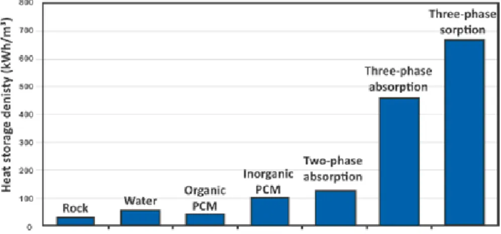
The discharge or absorption process of a triple-state thermochemical store therefore sees the utilisation of a large concentration difference where a solid-gas reaction with the salt hydrate crystals occurs forming a solution and then a liquid-gas reaction ensues. During these processes energy can be harnessed for heating or cooling from the thermochemical store. The presence of the crystallisation /solid-gas reaction phase in the cycle has the advantage of sig-nificantly increasing the storage density when some or all of the water mole-cules are removed from the salt crystal (see Figure 5).
Figure 5: Heat Storage Energy Densities of Various Energy Storage Media (Three-phase absorption: cycle with triple-state crystallisation process. Three-phase sorption: cycle with triple-state crystallisation and dehydration) [31]
Various salts may be used in the triple-state thermochemical process, where some of those studied have been CaCl2, LiCl and LiBr. When selecting
a salt for an application it is important to know its properties especially in terms of the solution and crystallisation temperatures. Of the aforementioned salts, working with water as the sorbent, LiBr has the highest crystallisation temperatures while LiCl has the highest energy density. This triple-state ther-mochemical cycle exhibits significantly higher therther-mochemical energy den-sity (approximately 1250 Wh/kg-salt for lithium chloride) than the more tra-ditional two-state absorption cycles [31].
3.3 Sorption Heat Pump Module Characteristics
Sorption module is, for the purposes of this study, the name given to a tubular heat pump device whose operation is based on the triple-state thermochemical storage cycle. This modular sorption component has been developed with the main premise of addressing the market penetration limitations of solar thermal heating and cooling systems; namely system size and cost, and the technical limitations due to system control, corrosion, crystallisation and leakage.
The sorption module functions in a batch absorption process where there are two main operational modes; absorption and desorption (also known as regeneration) [32]. The module comprises two cylindrical components, the reactor and the condenser/evaporator. These are made from inert materials (mainly glass), fused and sealed together under high vacuum. The reactor
component contains a matrix infused with the hygroscopic salt lithium chlo-ride (LiCl), while the other end of the module, the condenser/evaporator, con-tains pure water. The latter component may act as either condenser or evapo-rator depending on the flow direction of the water vapour within the module.
During the process of absorption, the difference in vapour pressure between the salt and the pure water causes water to evaporate from the end of the mod-ule (acting as an evaporator in this case) and form a salt hydrate and/or salt solution in the reactor. This process creates a temperature difference between evaporator and reactor where the evaporator can absorb heat at below ambient temperatures, creating a cooling effect, while heat is rejected at above ambient temperature from the reactor. This process continues until all water has been transferred from the condenser/evaporator and absorbed into the reactor ma-trix. The sorption module can then be ‘regenerated’ by heating the reactor to force water desorption from the salt in the reactor matrix where it condenses on the opposite end of the tube (now acting as a condenser) with condensation heat being removed at above ambient temperature. The regeneration process is aptly called desorption.
With an appropriate heat exchanger attached to the reactor and to the con-denser/evaporator, thermal energy can be added or removed from the sorption module for the provision of heating, cooling and/or energy storage. The heat exchangers via which thermal energy is provided to or removed from the sorp-tion module are therefore critical components for its proper operasorp-tion. The heat exchangers’ designs are based on the intended application for the sorption module; therefore the operation of the sorption module is governed only by the input temperatures and rate of input and removal of thermal energy. Due to their sealed nature with no internal moving parts and inert materials em-ployed, the sorption modules are designed to be completely maintenance free. The relatively high energy storage capacity improves the system’s overall ef-ficiency since the energy storage content is significantly higher than the sen-sible heat that needs to be removed before useful cooling can be delivered (i.e. low thermal mass of the sorption module).
Desorption
Phase
Absorption
Phase
Reactor
T
desT
abs Condenser/ EvaporatorT
evapT
cond Water VapourFigure 6 shows schematically the operation and thermal energy inputs and output of the sorption module. The module functions with thermal energy transfers occurring at three principal temperature levels:
Desorption temperature (Tdes) is the temperature at which heat is
sup-plied to the sorption module to incite the desorption process. This tem-perature level is determined by the temtem-perature at which heat is re-jected from the condensing vapour. There is a minimum temperature difference between salt and condensing vapour that must be reached before the desorption process commences.
Heat rejection or re-cooling temperature is the temperature at which heat is rejected from the sorption module. During desorption it is de-noted as the condensation temperature (Tcond) where heat is rejected
from the condenser/evaporator of the module. During absorption, it is denoted as the absorption temperature (Tabs) which is the temperature
level at which heat is rejected from the reactor.
Cooling temperature or evaporation temperature (Tevap) the
tempera-ture at which the module absorbs thermal energy creating a cooling effect on its surroundings.
Figure 6: Sorption module operation – thermal energy and tempera-ture levels in desorption and absorption phases
3.4 Sorption Modules in Combined Solar Heating and
Cooling Systems
The sorption module can be designed for direct integration into a conventional solar thermal collector. In this case the reactor of the module is covered by a metallic solar absorber plate heat exchanger with selective surface coating on the upper side. On the lower side pipes for heat transfer fluid flow are fitted to the heat exchanger. The condenser/evaporator is covered by a jacket type heat exchanger. The modules are then held in a modified solar thermal collec-tor housing for installation similar to that of a standard solar colleccollec-tor. The principal difference being that the sorption collector would have connections for two separate hydraulic circuits one for heat exchange with the reactor and absorber and one specifically for heat exchanger with the condenser/evapora-tor of the modules.
3.5 Sorption Integrated Collectors
The sorption module integrated solar thermal collector, sorption integrated collector (SIC) or simply sorption collector can be designed in various ways depending on the system operation attributes and installation requirements. Three designs have been conceptualised and can be subdivided into collectors which use liquid as the heat transfer medium and collectors that employ air as the heat transfer medium.
Figure 7: Sorption module integration in a flat plate solar thermal collector
3.5.1 Liquid Based Collectors
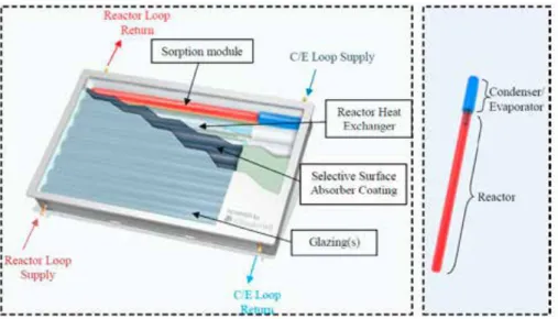
3.5.1.1 Flat Plate CollectorThe sorption module can be integrated into a flat plate collector, which has a flat absorber sheet with attached heat transfer fluid pipe on the underside of the absorber. The absorber is then manufactured such that there are undula-tions where the cylindrical reactor section of the sorption module can be in direct contact with the absorber. The condenser evaporator is covered by a jacket heat exchanger for each module, and these are interconnected by hoses within the collector. The sorption integrated solar thermal collector can be made up of as many modules as necessary, connected in series or parallel via their respective heat exchangers. In the collector concept shown in Figure 7 the collector houses 8 sorption modules connected in series on the reactor and condenser/evaporator sides. Therefore each collector has two separate hydrau-lic loops, one for the reactor heat exchangers of the modules and the other for the condenser/evaporator heat exchangers of the modules. The conden-ser/evaporator assembly of the modules is here also covered from solar radia-tion to allow for more efficient desorpradia-tion.
3.5.1.2 Evacuated Tube Collector
The sorption modules can also be integrated into a solar thermal collector us-ing evacuated tubes. In this case the sorption modules are outfitted on the re-actor portion with metallic heat exchange flanges to which pipes for heat trans-fer fluid are welded. This is then covered completely with an evacuated glass tube with integrated absorber (Sydney tube). Just as with the flat plate collec-tor type the condenser/evaporacollec-tor is covered with a jacket heat exchanger and all heat exchangers interconnected in series. The condenser/evaporator assem-bly of the modules is here also covered from solar radiation to allow for more efficient desorption. By using evacuated tubes along with the sorption mod-ules it makes it possible to have lower thermal losses and thus higher reactor temperatures during desorption and consequently also higher heat rejection temperatures during desorption than with a FTC [33].
3.5.2 Air-Based Collectors
Given that sorption modules operate solely by the input or extraction of ther-mal energy at different temperature levels, it is the heat exchanger type that governs how this thermal energy transfer is carried out. Air is thus a plausible heat transfer fluid where air heat exchangers for the sorption modules can be designed accordingly. Similar to a liquid-based sorption module integrated solar thermal collector, the air-based collector comprises a solar absorber at-tached to the reactor of the sorption module which allows for direct solar ab-sorption and heat transfer to the reactor. This solar absorber also comprises fins that allow for efficient heat rejection when air is blown across its surface. The condenser/evaporator is surrounded by a finned heat exchanger for heat rejection during desorption mode and for producing chilled air when air is blown across it in absorption mode. This type of sorption collector has been developed for integration into a roof (Figure 9) or building façade (Figure 10). The collector has integrated fans and ducting to allow for exhausting hot air during desorption (in summer) and blowing chilled air directly into the space to be condition during the absorption mode of operation [34].
Figure 10: Air-based sorption integrated collector integrated into a facade Figure 9: Air-based sorption integrated collector for roof mounting
3.6 Sorption Integrated Collector System Operation
The sorption integrated solar thermal collector solar heating and cooling system (SISHCS) has three primary modes of operation; two modes in the summer and one in the winter.
In winter, the system functions like a conventional solar thermal installa-tion where, when solar radiainstalla-tion heats the collectors’ absorber to a useful tem-perature, a pumped flow of heat transfer fluid is commenced to capture the thermal energy for heat supply and/or storage. If the absorber temperature falls below a useful level then the pump is stopped, terminating the flow of heat transfer fluid to the absorber heat exchanger until sufficiently high tempera-tures are obtained to recommence pump operation.
In summer, during the day, the system operates in desorption mode. The absorber and thus the reactor of the sorption modules are heated by solar radi-ation while the condenser is shaded from the sun and cooled by a re-cooling fluid. There is no circulation of fluid in the solar absorber heat exchanger in this mode. When the absorber temperature reaches the required level to pro-vide the requisite pressure difference between reactor and condenser/evapora-tor, desorption begins, and refrigerant vapour evaporates from the salt in the reactor and condenses in the condenser/evaporator. This condensation heat is transported away by the re-cooling fluid and exhausted via a heat sink (this can be a dry cooler, ground source heat exchanger or low temperature heating load). This process is called desorption and continues with the drying of the salt in the reactor (i.e. concentrating of the salt solution) until radiation levels are too low to maintain it. At sunset the reactor is cooled down via a flow of re-cooling fluid. In this intermediate period between desorption mode and ab-sorption mode, also known as swap mode, the absorber needs to be cooled down from between 80°C and 120°C (typical desorption level temperatures) to around 30°C to 40°C (typical absorption level temperatures). The resulting sensible thermal energy may be recovered for domestic hot water (DHW) pro-duction in the summer period. As the reactor cools, the internal pressure falls causing the condensed refrigerant in the condenser/evaporator (now acting as an evaporator) to evaporate producing a chilling effect, thus the system runs in absorption mode. Chilled fluid can thus be obtained directly from the con-denser/evaporator heat exchanger of the SIC. This chilled fluid may be stored (for daytime use) and/or serve the cooing load during the night. The SIC there-fore operates on a day-night batch process principle similar to that described by [35,36].
3.7 Absorption chiller integration of the sorption
module
The sorption modules may also be utilised in a more standard absorption chiller type application where the regeneration heat can be from any source. Thermal energy for regeneration is fed into the modules via a flow of heat transfer fluid in a pipe and flange heat exchanger on the reactor side of the module. The condenser/evaporator would possess a similar heat exchanger (see Figure 11). For this application the tubes are placed in two heat exchanger racks allowing for desorption and absorption processes to be performed in each rack separately such that when one rack is in the desorption mode the other is in the absorption (i.e. cooling delivery) mode. This alternating phase operation provides for quasi-continuous cooling delivery similar to the opera-tion of standard adsorpopera-tion chillers. The racks may be built for any number of modules connected in parallel and therefore any cooling power and/or energy storage capacity. Additionally, modules may be interconnected in series to crease effective temperature lift or any combination of series and parallel in-terconnection as required by the application. This application of the sorption modules is however outside of the scope of the current study.
Figure 11: Concept for absorption chiller integrated sorption modules. Sorption modules (grey) covered by heat exchange flanges (white) interconnected by pipes for heat transfer fluid (or-ange)
![Figure 3: Conceptual example of summer and winter operations of a combined solar heating and cooling system [7]](https://thumb-eu.123doks.com/thumbv2/5dokorg/4674062.122128/33.718.126.628.167.784/figure-conceptual-example-summer-operations-combined-heating-cooling.webp)
![Figure 4: Pressure vs temperature phase diagram depicting the triple-state process [31]](https://thumb-eu.123doks.com/thumbv2/5dokorg/4674062.122128/38.718.95.593.159.504/figure-pressure-temperature-phase-diagram-depicting-triple-process.webp)