Postprint
This is the accepted version of a paper published in Journal of Asian Electric Vehicles. This paper has been peer-reviewed but does not include the final publisher proof-corrections or journal pagination.
Citation for the original published paper (version of record): Aldammad, M., Ananiev, A., Kalaykov, I. (2016)
Current Collector for Heavy Vehicles on Electrified Roads: Field Tests. Journal of Asian Electric Vehicles, 14(1): 1751-1757
Access to the published version may require subscription. N.B. When citing this work, cite the original published paper.
Permanent link to this version:
Current Collector for Heavy Vehicles on Electrified Roads: Field Tests
Mohamad Aldammad 1, Anani Ananiev 2, and Ivan Kalaykov 31 Center for Applied Autonomous Sensor Systems, Örebro University, mohamad.aldammad@oru.se 2 Center for Applied Autonomous Sensor Systems, Örebro University, anani.ananiev@oru.se 3 Center for Applied Autonomous Sensor Systems, Örebro University, ivan.kalaykov@oru.se
Abstract
We present the field tests and measurements performed on a novel current collector manipulator to be mounted beneath a heavy vehicle to collect electric power from road embedded power lines. We describe the concept of the Electric Road System (ERS) test track being used and give an overview of the test vehicle for testing the cur-rent collection. The emphasis is on the field tests and measurements to evaluate both the vertical accelerations that the manipulator’s end-effector is subject to during operation and the performance of the detection and tracking of the power line.
Keywords
current collector, electrified road, hybrid electric vehi-cle, electric road system, field test
1. INTRODUCTION
The tendency to replace the fossil fuels used by vehi-cles with electrical energy nowadays is clearly identi-fied worldwide. While the solution of storing electrical energy in batteries for small vehicles seems to be rela-tively effective, large vehicles like trucks and buses require a non-realistic large amount of batteries when driving to distant destinations. Therefore, transfer-ring electricity continuously to vehicles while driving seems to be the solution [Ranch, 2010] by equipping the roads with electrical lines and the vehicles with a current collecting subsystem.
A conductive approach to collect electric power is popular since many years, mainly in city transporta-tion (trams, trolleybuses) and trains, using pantograph to connect to an overhead catenary line. Alternatively to overhead lines, the conductive approach can be implemented on a ground-level with road-embedded power lines and an appropriate current collector mounted beneath the vehicle, like the Alstom’s APS “Alimentation Par le Sol” technology [Alstom, 2008, 2012], or Ansaldo’s STREAM concept [Siciliano et al., 2002], [AnsaldoBreda, 2009], or like the tradition-al underground trains (metro) power supply system. The STREAM system has more complex and expen-sive infrastructure and the APS technology has already proven efficiency for tramways, due to the fixed rails and “third rail” power line.
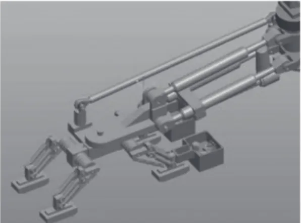
We have previously developed a prototype of a novel current collector system, Figure 1, designed for use in combination with adapted Alstom’s APS technology to
road vehicles, where two conductive metal power lines are embedded into the road surface, Figure 2. This current collector system consists of a two degrees of freedom manipulator with a block of current collector shoes attached to its end-effector. Its kinematic model has been detailed in [Aldammad et al., 2014a, 2014b].
Fig. 1 The developed current collector prototype,
taken from Aldammad et al. (2014b)
Fig. 2 Field test of the current collector, taken from
In this paper we present the adapted APS test track to road vehicles along with the field tests and measure-ments performed on our developed current collector. In Section 2 we describe the used test track, while in section 3 we give an overview of the test vehicle be-ing used along with the different subsystems installed for testing current collection. Finally, in Section 4 we describe the field tests and measurements performed on our current collector and present the results ob-tained during complete real runs on the test track.
2. TEST TRACK
To illustrate the adapted APS test track we have used to prove the feasibility of the ground-level power supply to road vehicles, we begin by giving a brief explanation about the APS system used in tramways, and then present the concept of the Electric Road Sys-tem (ERS) to feed road vehicles with electric power. Furthermore, we will highlight the main differences between the APS system and the ERS, and finally describe the adaptation of the APS system to the ERS test track we have used in our tests.
2.1 APS principle
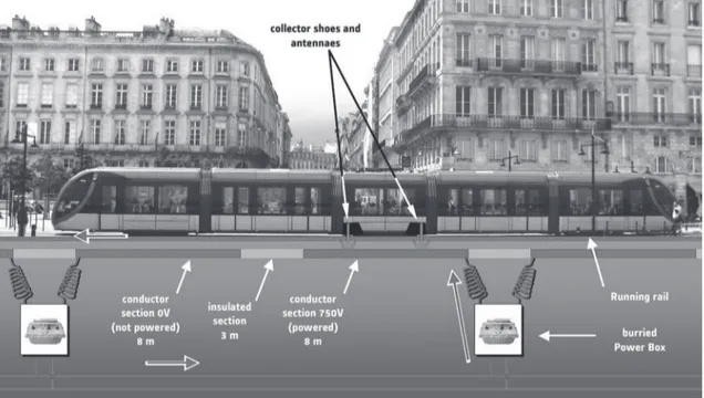
The basic principle of the APS system is a segmented power supply rail, which is fully integrated into the track platform [Viktoria Swedish ICT, 2014]. This system presents no danger to pedestrians and equip-ment as its principle consists of only supplying volt-age to the power rail segment that is physically oc-cupied by the vehicle. Furthermore, the APS system is designed to deliver the same power as the Overhead
Contact Line (OCL) in tramways does, delivering to a running tram a power of 1.1 MW with a DC voltage of 750 V and a current of 1500 A. The power rail seg-ments have a length of 11 m each. Every segment is located in the center of the track, between the running rails, and is made of a conductive section of 8 m and an isolating section of 3 m, see Figure 3. The length of the isolating section allows crossing railroad switches without power supply interruption. While the positive pole ‘‘+Vpower’’ is provided by the occupied conduc-tive section of the power rail to the current collector shoes, the running rails act as a ‘‘Ground’’ for the re-turning current through the tram wheels.
The power collection is achieved by equipping the tram with two collector shoes that slide on the power rail. These shoes are spaced of more than 3 m to en-sure that a least one collector shoe collects the power if the second one is above the isolating section. The APS infrastructure is embedded in the track and is composed of power rail segments, running segments, power boxes and loops for tram presence detection via a coded radio signal emitted by the tram. The power boxes, equipped with the power supply and switch-ing capabilities, are located in underground manholes between the rails every two segments (22 m) along the track.
2.2 Electric road system (ERS)
The Electric Road System (ERS) is defined as the road supporting dynamic electric power transfer to Elec-tric Vehicles (EV) or Hybrid ElecElec-tric Vehicles (HEV) driving on it [Viktoria Swedish ICT, 2014].
cally, the ERS could be based on power transfer from above, from the side, or from under the vehicle. The power transfer from above is the most mature technol-ogy as it has been used in e.g. trolley buses for many decades. Such a solution is suitable for the heavy transportation segment but it excludes passenger ve-hicles since the current collector would be unrealisti-cally long. The power transfer from the side of the road would be suitable for most kinds of vehicles but the potential number of lanes to be electrified would be limited. The electricity transferred from the roadside would also cause increased danger to vehicles in an ac-cident or to people and animals on the side of the road. Consequently, we address here in this paper the solu-tion of electric power transfer from the road below the vehicle. This solution could have a high potential, as it could be viable for both heavy and passenger vehicles and thus sharing infrastructure costs.
Furthermore, there are two main technologies of elec-tric power transfer from an ERS to the vehicles - con-ductive and incon-ductive technologies. In the concon-ductive technology, the power is transferred by establishing a physical contact between the vehicle and a conduc-tor built into the road. Consequently, this technology requires equipping the vehicle with a current collector, also known as a pick-up, which follows the electrified road and acts as the interface between the road and the vehicle. With the flexible highway vehicles, unlike trains that are bound to follow the rails, the current collector needs to be active and capable of following the ERS with the ability to connect and disconnect de-pending on the driving behavior and road conditions. With the inductive technology, the power is transferred wirelessly through a magnetic field and no physical contact between the road and the vehicle is required. To enable the power transfer, a conductor (comparable to the primary side of a transformer) inside the road generates a magnetic field that can be obtained in the vehicle equipped with a type of pick-up corresponding to the secondary side of the transformer and conse-quently converted into electrical current. To ensure a high efficiency of power transfer, the transfer distance and ability to follow the road conductor are important issues to be considered.
2.3 Differences ERS - APS
There are some significant differences between the APS system designed for trams and an ERS designed for road vehicles. In contrast to a tramway system, where the vehicles are strictly controlled in terms of type and dimension, there will be several different types of road vehicles utilizing an ERS [Viktoria Swedish ICT, 2014]. As these vehicles, such as trucks and cars, have differ-ent lengths, a powered APS segmdiffer-ent of 11 m would be too long to be totally covered by a small car, see Figure 4. It is therefore necessary to implement some safety measures when it comes to adapt the APS system to ERS in order to feed small vehicles.
Furthermore, the isolating section of 3 m between any two consecutive conductive sections in the APS system would make it impractical to have two collec-tor shoes spaced with more than 3 m for small cars. This problem is resolved in the ERS by using isolat-ing sections of only 40 cm, which make it practical to have collector shoes spaced with more than 40 cm for small cars. Another major difference is that the col-lector shoes in the APS system have a fixed position with respect to the vehicle and the power rail due to the guiding running rails that keep the shoes always in position. The ERS, on the other hand, will need movable and consequently active controlled collector shoes to track the power line due to the permissible slight maneuvering of the road vehicle around this line. Furthermore, only one polarity for the collector shoes is needed in the APS system to connect to the unipolar power rail as the returning current passes through the conductive wheels into the running rails, while two polarities collector shoes are needed in the ERS to connect to a bipolar power line due to lack of running rails. With the power needed to operate a tram, the maximum power delivered by an active APS segment is 1.1 MW, while it will be enough to deliver 120 kW per active segment in an ERS based on the maximum consumption for a heavy road vehicle. One should note here that both the APS system and ERS are designed such as an active segment delivers power to only one tram and one road vehicle respectively at a time. 2.4 Adaptation of the APS system to ERS
The adaptation of the APS system to ERS is realized
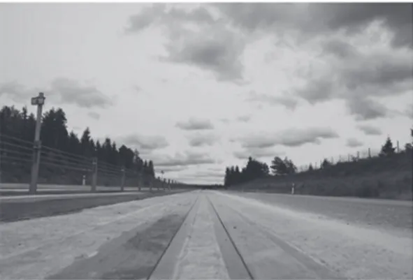
by Volvo Group together with Alstom through the construction of a 400 meter-long test track at Volvo’s facility in Hällered near Gothenburg in Sweden [Volvo, 2013]. The purpose of the track is to test the ground-level power supply to road vehicles through the use of our developed current collector mounted on a truck and consequently validate the adapted APS technology to feed road vehicles. The test track entails a bipolar power line built into the surface of the road along its entire length as depicted in Figure 5.
The positive pole “+Vpower” and the negative pole “Ground” used to return the current are located in the middle of the lane. They have a width of 10 cm each and are spaced by 15 cm. The entire power line is sectioned into segments of 11 m that are separated by isolating sections of 40 cm. Only one segment is powered at a time when the vehicle is positioned over this segment, leaving the other segments unpowered. Consequently, to assure a continuous power supply to the vehicle along the track, a sequential switching between the consecutive segments is achieved when the vehicle passes from one segment to the next one. For this purpose, the vehicle is equipped with a ra-dio emitter, which the road segments can sense. If an electric vehicle passes a road segment with a properly encrypted signal, then the road will energize the seg-ments that sense the vehicle [gizmag, 2013], [Viktoria Swedish ICT, 2014]. As an additional safety measure, the current flows only when the vehicle is moving at speeds greater than 60 km/h. If someone steps over an energized section then he will most probably be run over by the vehicle before he gets an electric shock. All these measures make this electric feeding from the road safe from an electric point of view [Aldammad et al., 2014b].
3. TEST VEHICLE
For a complete test of electric power transfer from the ERS, it will be mandatory to have a hybrid vehicle equipped with the necessary interface components to
its hybrid system. But as this is not needed during the development phase of interface components, we have limited our tests to a Volvo FH diesel combustion truck equipped with a resistor bank to dissipate the collected electric power.
A system overview of the test vehicle is depicted in Figure 6. The added new subsystems to the test vehi-cle are:
• an additional 24 V battery to feed the current col-lector control box;
• a resistor bank mounted above the vehicle’s chas-sis to dissipate the electric power that is transferred to the vehicle from the ERS. This bank consists of a container of 1 m3 filled with water and equipped with 12 heater elements of 18 kW each for power dissipation;
• an electrically safe box inside the cabin. This box contains a PC for supervisory control of the current collector controller and data acquisition from the different sensors, an oscilloscope for transferred power visualization and analysis, a display screen for the monitoring camera and a radio emitter to energize the appropriate segments of the ERS; • monitoring and logging cameras;
• a current collector attached to rear of the vehicle; • a current collector control box that contains the
controller, the DC motors drives and the data ac-quisition system;
• a radio emitter tuner and an antenna attached to the current collector.
4. FIELD TESTS AND MEASUREMENTS
With the test vehicle equipped with our developed current collector, we have carried out some tests and measurements using the ERS test track built to vali-date the concept of ground-level power supply to road vehicles.
Fig. 5 ERS test track
4.1 Measurement of vertical accelerations
The vertical accelerations acting on the vehicle and the manipulator’s end-effector while the vehicle is moving have been measured in 2 configurations. The first one is when the end-effector is placed in its home
position, while the second one is when the
end-effec-tor is tracking the power line. The acceleration meas-urement is achieved by using two accelerometers— one attached to the vehicle’s chassis and the other attached to the manipulator’s end-effector [Aldammad et al., 2015].
4.1.1 1st configuration: end-effector placed in home position
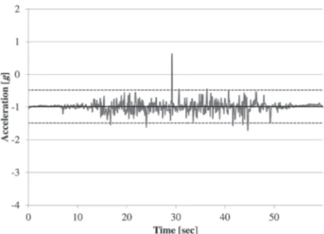
The measurement of the vertical acceleration of the vehicle’s chassis when the end-effector is placed in
home position and the vehicle is moving, shown in
Figure 7, reveals a value of (–1 ± 0.36) g, taking into account that the vertical axis of the accelerometer is directed upward. At the same time, the measurement of the vertical acceleration of the end-effector, shown in Figure 8, gives a value of (–1 ± 0.53) g. The
verti-cal acceleration is slightly bigger at the end-effector in comparison with the vehicle’s chassis due to the hanged position of the manipulator with respect to the chassis, making the manipulator subject to more verti-cal acceleration than the chassis.
4.1.2 2nd configuration: end-effector tracking the power line
The measurement of the vertical acceleration of the vehicle’s chassis when the end-effector is tracking the power line, shown in Figure 9, reveals a value of (–1 ± 0.50) g. At the same time, the measurement of the vertical acceleration of the end-effector, shown in Figure 10, gives a value of (–1 ± 1.06) g. This means consequently that the end-effector is subject to the double vertical acceleration of the chassis vertical ac-celeration. This results leads to some implications on the mechanical design of the manipulator as it has to overcome this acceleration.
All the previous accelerations are measured by assum-ing a normal distribution around the average vertical acceleration value of –1 g, which is in fact the gravity.
Fig. 7 Vertical acceleration of the vehicle’s chassis
when the end-effector is placed in home position and the vehicle is moving
Fig. 8 Vertical acceleration of the end-effector placed
in home position when the vehicle is moving
Fig. 9 Vertical acceleration of the vehicle’s chassis
when the end-effector is tracking the power line
Fig. 10 Vertical acceleration of the end-effector when
Accordingly, the tripled standard deviation of this dis-tribution is adopted as an estimate of the acceleration amplitude.
4.2 Detecting the power line when the vehicle is sta-tionary
We have first tested, during the development stage of the current collector manipulator, the detection of the power line in the laboratory after mounting the manipulator on a fixed stand that simulates the vehi-cle’s chassis, i.e. at the same height above the ground as when mounted on the vehicle, and placing on the ground two metallic plates that simulates the two poles of the power line. This test has allowed to test in laboratory the static functionalities of the manipulator before mounting it on the vehicle. In this test, the ma-nipulator starts from home position and goes down to
scanning level where it executes a scanning to detect
the power line and then establishes the contact with it when detected [Aldammad et al., 2014a]. We have also done this test on the stationary test vehicle placed over the power line after mounting the manipulator on the chassis. The satisfactory results obtained in these static tests regarding the detection and establishment of contact with the power line was necessary before going further with the dynamic tests, i.e. when the ve-hicle is moving.
4.3 Tracking a non-electrified power line when the vehicle is moving
We have decided to conduct at the beginning the dy-namic tests of the current collector manipulator on a non-electrified power line and then to move to tests on an electrified line.
Due to the short testing track of only 400 m and in or-der to evaluate the tracking performance of the manip-ulator as long as possible during a complete run, we have been limited in our field tests to start the tracking of the power line immediately after the vehicle starts moving. The detection of the power line starts when the vehicle is still stationary. The vehicle starts mov-ing immediately after the line has been detected and the connection to the power line has been established. A graphical representation of one of the tests of power line detection and tracking during a complete run over the whole test track is depicted in Figure 11. In this test we have chosen the configuration of sensors that uses two short range sensors which respond when coming over the line [Aldammad et al., 2015]. The horizontal axis represents the time, while the verti-cal axis stands for the sensors’ states. The long range sensors’ state takes the value “2” when the power line is detected, otherwise it takes the value “0”. Further-more, the short range sensors’ state takes the value “0”
when the shoes are aligned with the power line, “–1” when the shoes are deviated to right of the power line and “1” when they are deviated to the left of it. When the vehicle reaches the constant speed of 30 km/h starting from the stationary state, a periodic behavior is clearly identified by the long range sensors’ state. This state remains within a period at the value “2” for 1.32 sec which corresponds to the traveled distance on a complete power line segment of 11 m, and then followed by the value “0” for 48 ms corresponding to the passage across an isolator plate of 40 cm. One can count from this graphical representation during a com-plete run over the whole test track for 25 track seg-ments and 24 isolator plates. The test starts at instant t = 7 sec when the power line is detected and lasts for almost 40 sec. During this period the power line is tracked continuously to keep the collector shoes on the line. One can count from the short range sensors’ state variation in this test for 20 corrective actions by the controller to realign the shoes with the power line. This gives a rough idea about the task volume needed by the controller to track the power line continuously. 4.4 Tracking an electrified power line when the ve-hicle is moving
We have done in this test exactly the same procedure in testing the tracking of the power line as in the non-electrified power line case. Our main concern here is to see if there are some effects on the manipulator’s functionality arising from the power feeding from the ERS, such as the electromagnetic interference that may affect the manipulator’s sensory and control sys-tem.
A graphical representation of one of the tests of power line detection and tracking when the line is electrified is depicted in Figure 12. In this test we have again chosen the sensors configuration that uses two short range sensors which respond when coming over the line.
The detection and tracking behavior in this test is sim-ilar to what has been experienced during the test with the non-electrified power line, leading consequently to conclude that the electrified power line has no tangible effect on the performance of the sensory and control system of the manipulator.
5. CONCLUSION
In this paper we have presented the main considera-tions in the field tests carried out on the current collec-tor manipulacollec-tor. We have:
• presented the used ERS test track which is an adapted APS system for ground-level power supply to heavy road vehicles;
• exposed the measurement results of the vertical ac-celeration acting on the manipulator’s end-effector both in home position and when tracking the power line and concluded about the implications of this acceleration on the mechanical design of the ma-nipulator;
• illustrated and evaluated the performance of detec-tion and tracking of the power line with our current collector during a complete real run on the test track and concluded about the task volume needed by the controller to track the power line continu-ously.
Acknowledgements
Authors are grateful to Volvo Trucks, Gothenburg, Sweden, whose financial support, team work and excellent field test conditions gave the possibility to materialize the proposed concepts.
References
Aldammad, M., A. Ananiev, and I. Kalaykov, Current collector for heavy vehicles on electrified roads,
Proceedings of the 14th Mechatronics Forum Inter-national Conference, Mechatronics 2014, 436-441,
Fig. 12 Power line tracking (electrified line)
2014a.
Aldammad, M., A. Ananiev, and I. Kalaykov, Current collector for heavy vehicles on electrified roads: kinematic analysis, International Journal of
Elec-tric and Hybrid Vehicles, Vol. 6, No. 4, 277-297,
2014b.
Aldammad, M., A. Ananiev, and I. Kalaykov, Current collector for heavy vehicles on electrified roads: motion control, Journal of Asian Electric Vehicles, Vol. 13, No. 2, 1725-1732, 2015.
Alstom, APS 3D animation, 2012, http://www.alstom. com/press-centre/2010/11/APS-3D-animation. Alstom, Wireless Trams with APS, 2008, http://www.
its.uci.edu/~jaykay/transit-documents/catenary-free-LRT-Alstom:pdf.
AnsaldoBreda, TramWave: Ground-Level Power Sup-ply System, Booklet, 2009.
gizmag, Volvo’s electric roads concept points to bat-tery-free EV future, 2013, http://www.gizmag.com/ volvo-electric-road/27913.
Ranch, P., Elektriska vägar - elektrifiering av tunga vägtransporter (förstudie), Technical report, Gront-mij AB, April 2010.
Siciliano, V., and A. Del Naja, Power line for an elec-tric vehicle, August 2002, US patent 6427816. Viktoria Swedish ICT, Slide-in Electric Road System,
Conductive project report, Technical report, Vikto-ria Swedish ICT, 2014.
Volvo. The road of tomorrow is electric, 2013, http:// news.volvogroup.com/2013/05/23/the-road-of-tomorrow-is-electric.