V¨
aster˚
as, Sweden
Thesis for the Degree of Bachelor of Science in Engineering
-Computer Networks 15.0 credits
AUTOMATED DEPLOYMENT OF
CUSTOMER-PREMISES EQUIPMENT
Christian ˚
Aberg
cag12003@student.mdh.se
Examiner: Mats Bj¨
orkman
M¨
alardalen University, V¨
aster˚
as, Sweden
Supervisor: Nils M¨
ullner
M¨
alardalen University, V¨
aster˚
as, Sweden
Company supervisor: J¨
orgen Jonasson,
TDC, Stockholm
Abstract
Zero touch deployment tools perform installation and configuration of computer networking devices without human interaction. Modern zero touch deployment tools generally lack support for routers and are platform dependent. This forces Internet Service Providers to rely on manual node deploy-ment methods when deploying Customer-Premise Equipdeploy-ment which is time consuming and error prone. This thesis investigates how the process of deploying Customer-Premises Equipment can be automated and optimized. State-of-the-art is discussed to point out requirements and possible improvements. Based on that, a tool is implemented performing deployment of Customer-Premises Equipment while minimizing manual intervention. As Internet Service Providers typically work with equipment from various vendors, multivendor support is implemented. This thesis studies common methods for initial Customer-Premises Equipment configuration. Request for Comments and Technical manuals are consulted regarding network protocols, zero touch deployment tools and router operating systems.
Table of Contents
1 Introduction 1 1.1 Research Objectives . . . 1 1.2 Motivation . . . 1 1.3 Method . . . 2 2 Background 3 2.1 Node Deployment Concepts . . . 32.1.1 Request for Comments . . . 3
2.1.2 Computer Networking Basics . . . 3
2.1.3 Operating System Management . . . 5
2.1.4 Configuration Management . . . 6
2.1.5 Manual Node Deployment Methods . . . 7
2.2 Related Work . . . 8
2.2.1 Available Node Configuration Tools . . . 8
2.2.2 Zero Touch Deployment Methods . . . 9
2.2.3 Cisco Smart Install . . . 9
2.2.4 Juniper Zero Touch Provisioning . . . 11
2.3 Manual Node Deployment Study . . . 12
3 Platform Independent Deployment System (PIDS) 14 3.1 Architecture . . . 14 3.2 Kernel . . . 15 3.3 API . . . 16 3.4 User Interface . . . 18 3.5 Platform Drivers . . . 21 3.5.1 Profiles . . . 21 3.5.2 Kernel Instructions . . . 23
3.5.3 Console Cable Communication . . . 24
3.6 Console Cable Execution Methods . . . 24
4 Analyzing PIDS 27 4.1 Design . . . 27
4.2 Test 1: Single Deployment . . . 29
4.3 Test 2: Dual Deployment . . . 30
4.4 Test 3: Triple Deployment . . . 31
5 Interpretation 32 5.1 PIDS Performance . . . 32
5.2 PIDS versus Zero Touch Deployment Methods . . . 33
6 Conclusion 35
References 36
Appendix A Initial Configuration Study Manuals 37
List of Figures
1 Topology icons. . . 4
2 Network topology with device connections. . . 5
3 Configuration sent through a Console cable. . . 6
4 Configuration sent over SSH. . . 7
5 Configuration sent over an IP network. . . 7
6 A Console cable for network node configuration. . . 7
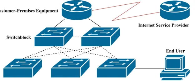
7 Example topology for Cisco Smart Install. . . 10
8 Example topology for Juniper Zero Touch Provisioning. . . 12
9 Device roles in the PIDS architecture. . . 14
10 Software architecture within the PIDS Server. . . 15
11 Concurrent deployment of two Cisco routers. . . 16
12 Concurrent deployment of two Juniper routers. . . 16
13 Client connecting to a server through PIDS API. . . 18
14 The Home-view in PIDS GUI. . . 18
15 Adding processes in PIDS GUI. . . 19
16 Viewing active processes in PIDS GUI. . . 19
17 Analyzing devices in PIDS GUI. . . 20
18 Selecting setup profile for devices in PIDS GUI. . . 20
19 Hold Timer operation in HBEM communication. . . 25
20 Demonstration of Expect Based Execution Method. . . 26
21 The topology when analyzing PIDS. . . 27
22 PIDS analysis - Topology for test 1. . . 29
23 PIDS analysis - Topology for test 2. . . 30
24 PIDS analysis - Topology for test 3. . . 31
25 Average deployment time (no system image upgrades). . . 32
26 Average deployment time (with system image upgrades). . . 32
27 PIDS two step deployment procedure. . . 33
28 S1 experiences failure and must be replaced. . . 34
29 S1 new replaces S1 and is automatically configured by Cisco Smart Install. . . 34
List of Tables
1 Configuration methods for network nodes. . . 82 Functions separated from the Startup Configuration in Cisco switches. . . 11
3 Available Manual Node Deployment Methods per platform. . . 13
4 Required variables for processes within the PIDS kernel. . . 15
5 PIDS kernel process list. . . 16
6 PIDS kernel process list after modification. . . 16
7 Request-packet types in PIDS API. . . 17
8 Drivers methods that must be callable by the kernel. . . 23
9 Methods available for the yost object. . . 24
10 Test result of analysis 1A. . . 29
11 Test result of analysis 1B. . . 29
12 Test result of analysis 2A. . . 30
13 Test result of analysis 2B. . . 30
14 Test result of analysis 3A. . . 31
15 Test result of analysis 3B. . . 31
16 Comparison of PIDS to Zero Touch Deployment Methods. . . 33
1
Introduction
A demarcation point is commonly understood by Internet Service Providers (ISP) as a point at which a ISP network end and a customer network begin. If an error occur within the customer side of the demarcation point, the customers is responsible to fix the error and vice versa.
ISP customers can generally choose the demarcation point placement. Due to its administrative simplicity, many customers choose to exclude the Internet connected routers (Customer-Premises Equipment) from the customer side of the demarcation point, thus handing over the equipment responsibility to the ISP. This responsibility includes:
• configuration, • deployment, • monitoring and
• troubleshooting of the Customer-Premises Equipment.
Zero Touch Deployment Methods automate deployment of networking equipment. Cisco and Juniper are two large actors in the networking equipment domain that have developed their own implementation of Zero Touch Deployment Methods for switches.
Switches (in their simplest form) provide end users with connectivity to a single computer net-work, as opposed to routers that interconnect multiple computer networks. Routers also have sup-port for various transmission media which is why routers often are selected as Customer-Premises Equipment.
1.1
Research Objectives
The process of deploying routers is not very streamlined with the absense of Zero Touch Deployment Methods. Deploying routers often involve manual configuration in various ways (Manual Node Deployment Methods). For this reason, this thesis studies the following objectives:
Objective 1: Determine how the process of deploying Customer-Premises Equipment can be
improved. This is achieved by investigating the requirements for an automated deployment process and by reviewing state-of-the-art tools.
Objective 2: Develop a tool (based on the knowledge from Objective 1 ) to perform an automated deployment of Customer-Premises Equipment. The tool is referred to as the Platform Independent Deployment System (PIDS).
1.2
Motivation
Consider a scenario where an Internet Service Provider (ISP) has to configure and deploy a large number of Customer-Premises Equipment for their clients. Manually configuring the nodes is a time consuming and error prone process and the Zero Touch Deployment Methods available only work with switches and not with routers.
The world is becoming more and more automated; but how come there are no efficient tools for automating Customer-Premises Equipment deployment? No Zero Touch Deployment Methods with support for routers was found, despite thorough research. What node deployment tools exist today and how do they work?
A tool automating deployment of Customer-Premises Equipment is developed and presented in this thesis. Different routers have varied deployment methods and functionalities which leads to the following questions:
• How do routers handle system images and configurations? • What are the methods of accessing unconfigured routers? • What Zero-Touch Deployment Methods exist today?
1.3
Method
In order for PIDS to achieve platform independency, it is important to have knowledge in current deployment methods for networking equipment. This thesis studies the following two fields:
• Current Zero Touch Deployment Methods and • current Manual Node Deployment Methods.
Current Zero Touch Deployment Methods are studied by reviewing documentation for common network operating systems (e.g. Cisco IOS or Junos OS). Current Manual Node Deployment Methods are studied by reviewing the documentation for various networking equipment. A study is performed to determine common methods when manually deploying unconfigured Customer-Premises Equipment from various vendors.
PIDS development starts after studying current Zero Touch Deployment Methods and Manual Node Deployment Methods. Finally, a study is conducted to determine the performance of PIDS.
2
Background
At times, network technicians and engineers encounter situations when a large amount of network nodes need to be configured with a standard template either before deployment or during upgrades. Typical scenarios include:
• Access layer node deployment: The access layer of a campus network architecture con-nects people (End Users) to an IP network. The node quantity requirements expand with the amount of end users.
• Pre-configuration of Customer-Premises Equipment: Internet Service Providers pro-vide customers with pre-configured equipment. Manual configuration of Customer-Premises Equipment is prone to errors.
• Network node upgrades: Network nodes need upgrading. Possible reasons are operating system patches or configuration changes. The need for network node upgrades embodies each layer of the network design architecture and can include a large number of devices.
Each scenario described above can be solved through manual configuration. Manual configuration of production equipment is both time consuming and prone to human errors.
According to J¨orgen Jonasson, Senior Network Architect at TDC1, some of these issues are addressed by creating configuration templates before deployment. Before the configuration can be transferred to a device, the system image of a network node needs to be adopted to accommodate the configuration template. The configuration template process is described below:
1. Identify the platform.
2. Check if the system image is compatible with the configuration template. If so, go to Step 3. (a) Install a compitable system image to the device.
(b) Restart the network node (if necessary). 3. Transfer the configuration template to the device.
4. Manually execute commands that could not be included in the configuration template. 5. Save the active configuration on the network node.
This process is repeated for each network node. Several current Zero Touch Deployment Methods automate deployment of network switches; but no such tool was found for routers despite through research.
2.1
Node Deployment Concepts
The following sections investigates some basic concepts composing the area of node deployment.
2.1.1 Request for Comments
Request for Comments (RFC) are a type of technical report describing functions and protocols for the Internet and computer networks (e.g. DHCP and RADIUS)2.
2.1.2 Computer Networking Basics
Computer networks allow computers and embedded systems to transmit data through a com-mon infrastructure. They consist of nodes contributing specific functions to the network. These functions include:
• Delivering data.
1May 2016 -http://tdc.se/
• Analyzing data for security threats.
• Preventing data from accessing specific resources. • Limiting data-throughput for individual nodes.
The computer networking field has a common terminology to describe the roles. Most of the ter-minology is standardized with RFCs. The following paragraphs describes the terter-minology relevant to this thesis:
IP Addresses: Devices participating in computer networks are assigned a unique IP-address. IP-adresses allow devices to initiate private data-flows between one another. If two devices are assigned the same IP-address, this is called an IP conflict and communication might be interrupted. There are several versions of IP and each version differs in functionality and amount of addresses.[1] IP Subnets: An IP Subnet is a range of IP addresses. If an ISP has ownership of an IP subnet, the range can be further divided into smaller subnets that the ISP can share with its customers. The Internet is divided into millions of subnets [2].
Router: Routers forward data between subnets. If a computer in one subnet needs to reach a device whose IP address is located in another subnet, the computer will forward the packet to a router. The router will make a decision on how to forward the data (this process is called routing). Routing will generally lead to one of three things:
• The router forwards the packet directly to the destination device.
• The router forwards the packet to another router that is between itself and the receiver. • The router has nowhere to forward the data, discards it and optionally returns a ICMP
Destination Unreachable to the sender.
Routing-decisions are generally based on sophisticated algorithms (Routing Protocols). Routers are the main building block of the Internet [3].
Switch: A switch performs data forwarding within a subnet. Switches forwards data based on MAC addresses instead of IP addresses.
Firewall: A firewall performs data analysis and is able to prevent intrusions to a private network. The firewall possesses a database of know vulnerabilities which is compared to analyzed data. If the data has a match in the database, the firewall discards the packet and optionally notifies an administrator [4].
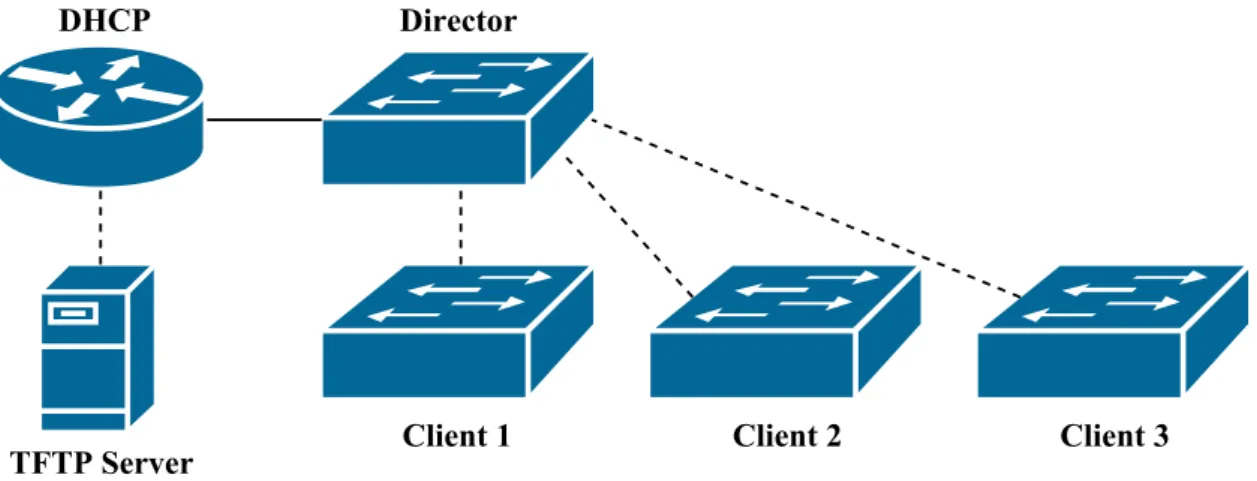
Network Topologies The physical connections in a Computer Network can be graphically represented in a Network Topology. Figure1 shows some icons for common devices in computer networks. Figure2shows how topologies can be help describing networks with (in this case) eight nodes and eleven interconnections:
The cable types connecting the nodes can also be determined by reviewing the topology. In Figure2, it is shown that the connection between the Customer-Premises Equipment and the ISP are of a different type than the rest of the topology.
There are no current standardizations addressing what icons to use in topologies. Instead, the networking company Cisco has published a set of icons which has been widely accepted today3.
Figure 2: Network topology with device connections.
2.1.3 Operating System Management
The operating system (OS) in a router provides for: • Resource Management
• Hardware Drivers • Node Functionality
Without an operating system, a router is not able to function. High-end Customer-Premises
Equipment are embedded systems with specialized hardware to perform routing. Thus, the CPU is not intensively interrupted during high data loads. The hardware performs routing-decisions based on previous instructions received by the OS [5].
The OS is crucial to a routers performance and it is therefore important to run an OS free from bugs in production environments. It is generally a good practice to update the operating system when new versions of the software become available. Vendors have different ways of managing the OS of their devices. It is therefore important to review the platform documentation before managing the operating system of a device. After upgrading the OS of a router, a couple of unexpected events can occur:
• Functions have been removed • Syntax has been changed • New bugs occur
The old configuration might therefore be incompatible to the new OS. It is important for the administrator to consider these events before upgrading production nodes. A downgrade with respect to the points above can also be considered as a good alternative of maintaining a stable production network.
2.1.4 Configuration Management
This section presents alternative ways to manage configurations in Customer-Premises Equipment.
Configuration Locations How a network node handles configurations depends on the active
operating system. There are multiple approaches vendors can take where simplicity is weight against functionality. The list below presents various ways nodes handle configurations:
• Single file: This is the simplest method from an administrators point of view. Only the single configuration file is read by the operating system and loaded into memory during node boot up.
• Multiple files: Some devices divide the configuration into multiple files. In these cases, there is often a main configuration file storing the most general parts of the devices configuration. The administrator needs to be aware of the file structure when performing configuration management, which adds a layer of complexity.
• Database: Databases provide additional functionality to the configuration management. Databases generally consist of a single binary file. Thus, the configuration structure is defined within the database file instead of the devices file system. The configuration database records changes over time and provides the administrator with an option to return to a previous version of the configuration. Cisco refers to this process as a Configuration Rollback [6, p.4-81].
It is necessary to determine how a device handles configurations before performing Configuration Management.
Applying Configurations There are generally two ways of transferring a configuration to a
node:
• Configuration through a Console Cable.
• Configuration through a remote management protocol. • Transferring a configuration file from a remote file server. All three methods are described below:
Console Cable Configurations can be applied to a device through a Console Cable. Console
Cable management is considered as Out-of-band because it is not carried out via an IP network. Figure3demonstrates a computer sending an configuration to a router through a console cable.
Figure 3: Configuration sent through a Console cable.
Remote Management A device can be configured remotely over an existing IP network.
Re-mote management protocols are considered In-band. Common protocols include: • SSH
The device must have IP connectivity for remote management protocols to function. If for some reason the device loses connectivity as of misconfiguration, the device might never be reachable with remote management techniques again, until the misconfiguration is fixed by other means.
Figure4demonstrates how a person in Stockholm can configure a device in Oldenburg through remote management protocols.
Figure 4: Configuration sent over SSH.
Remote File Server Configurations can be transfered to a device from an IP based file server. This method is considered a In-band-management technique since the configuration is carried over an existing IP network. Common protocols for sending configurations include:
• HTTP • FTP • TFTP
Before a configuration can be sent remotely to a node, all participating devices require IP addresses and permissions to establish sessions between one another. Figure5demonstrates a scenario where a configuration is transfered to a device over an existing IP network:
Figure 5: Configuration sent over an IP network.
2.1.5 Manual Node Deployment Methods
Figure 6: A Console cable for network node configuration.
Before network equipment can function in production environments, the equipment must be configured. For example:
• An administrator might need to activate remote management services for a device. • An administrator needs to secure the node by setting an access password.
If the equipment has factory default settings, the techniques for accessing and configuring the devices vary in regard to the platform. Some devices require the administrator to access the device through a console cable (Figure 6) while others initially must be configured with remote
management techniques such as HTTP and Telnet. Table 1 presents two common deployment
methods:
Method Description
GUI-based Some devices require initial configuration to be performed
re-motely through a web browser or some specialized application. A pre-configured IP address is required on the device for it to be accessible for the administrator.
CLI-based Some devices require initial configuration to be performed
Out-of-band through a console cable.
Table 1: Configuration methods for network nodes.
Section2.3 investigates what Manual Node Deployment Methods are most common for
enter-prise equipment as of March 2016.
2.2
Related Work
Several tools exist that automate different aspects of network management. Many vendors have developed their own proprietary configuration management tools for their products.
Cisco Smart Install and Juniper Zero Touch Provisioning respond well to the Problem Formu-lation and were therefore studied in more depth in Section2.2.2.
2.2.1 Available Node Configuration Tools
The following section presents some of the available tools for automated node configuration. A brief discussion is included for each tool. The tools are listed in alphabetical order:
Ansible Ansible performs automated configuration deployment. By grouping network nodes,
Ansible can apply configuration changes to multiple devices at once. Ansible is open source and licensed under GPLv34.
Ansible connects to the nodes through remote management techniques. SSH is the default method. Thus, SSH needs to be manually activated on the nodes before Ansible can operate5. Cisco Smart Install Cisco Smart Install is a vendor specific and proprietary tool performing automated image and configuration deployment on Cisco switches. The tool can not operate on non Cisco based platforms since it is based on the proprietary protocol Cisco Discovery Protocol (CDP). Thus, Cisco Smart Install is not suitable in multivendor environments[7].
Juniper Zero Touch Provisioning Juniper Zero Touch Provisioning performs automatic
de-ployment of juniper switches without manual intervention. The client switches get informed (through DHCP options) about the location of an operating system image and a configuration file [8, p.63].
Juniper Zero Touch Provisioning is only applicable with Juniper switches. Considering that the methods behind Juniper Zero Touch Provisioning are based on DHCP options, other vendors could freely implement this solution [9].
4March 2016 - http://docs.ansible.com/ansible-tower/latest/html/installandreference/updates_
support.html
NetMRI NetMRI is a node management system which specializes in network discovery, network change automation and configuration compliance management. NetMRI has support for both traditional- and virtual nodes (like Cisco VRF). NetMRI is a proprietary software licensed under the Infoblox End-User License Agreement6.
The primary goal behind NetMRI is to provide a tool for performing change deployment and configuration compliance for preconfigured nodes. NetMRI is not intended for node deployment7.
SolarWinds Network Configuration Manager SolarWinds Network Configuration Manager
performs periodic configuration backups, configuration change monitoring and configuration change automation8. SolarWinds Network Configuration Manager is a proprietary software. The tool is intended for pre-configured environments and does not perform automatic node deployment. Summary: A lot of existing node configuration tools are developed to perform configuration management in pre-configured systems and networks. They provide for additional control in com-plex networks where node management is challenging. Most of these tools have no precise method to solve the problems as described in this thesis.
The most interesting of the tools in the scope of this thesis are Cisco Smart Install and Juniper Zero Touch Provisioning. Section 2.2.2 investigates how Cisco Smart Install and Juniper Zero Touch Provisioning perform node deployment.
2.2.2 Zero Touch Deployment Methods
Cisco Smart Install and Juniper Zero Touch Provisioning perform system image upgrades and configuration transfers. Both tools respond to the thesis problem formulation. Some shortages of the tools are:
• platform dependency,
• both tools are proprietary and • they only work with switches.
The following sections investigate the technical concepts, methods and communication protocols of the tools.
2.2.3 Cisco Smart Install
Cisco Smart Install performs system image upgrades and configuration of nodes. Cisco Smart In-stall requires no manual intervention after a client is plugged into a Cisco Smart InIn-stall compatible network.
The device managing a Cisco Smart Install network is called a Director. The Director com-municates directly to client switches. The client provides the Director with information regarding its:
• Main MAC address • Product Identification
The Director provides the client with knowledge about where to find the System Image and the Configuration File. The client then initiates the upgrade. The Cisco Smart Install architecture defines several roles:
• Client - The Client identifies itself to the Director in order to determine if any predefined System Image and Configuration File exist.
• Director - The Director communicates with clients and provides them with TFTP paths for the System Image and the Configuration File.
6March 2016 -https://www.infoblox.com/company/legal/eula-netmri
7March 2016 -https://www.infoblox.com/products/network-automation/netmri 8March 2016 -http://www.solarwinds.com/network-configuration-manager.aspx
• DHCP Server - The DHCP Server provides the client with: – an IP address and
– a destination IP to the TFTP Server.
• TFTP Server - The TFTP Server stores all system images and configuration files for the clients. A TFTP Server can be configured on the Director or on a remote server.
There are in total three communication protocols participating in the Cisco Smart Install archi-tecture:
• CDP - Cisco Discovery Protocol is a Cisco proprietary communication protocol. CDP com-municates through multicast addresses. Thus, no IP addresses are required on the nodes for the communication to function [10, p.321]. In Cisco Smart Install, the Director identifies the client with CDP.
• DHCP - Dynamic Host Configuration Protocol is a communication protocol that dynami-cally assigns IP addresses to network nodes. A DHCP Server can include additional variable data in its packages through DHCP Options [11]. In Cisco Smart Install, DHCP provide clients with IP addresses and a TFTP Server address. The Director inserts additional op-tions into the Offer from the DHCP Server through DHCP Snooping [12, p.1-2]. The following options are inserted into the DHCP Offer by the Director [12, p.1-5]:
– Option 67 - The Configuration File. – Option 125 - Vendor-Specific
∗ Suboption 5 - The image list file ∗ Suboption 16 - Director IP address
• TFTP - Trivial File Transfer Protocol is a communication protocol allowing clients to down-load and updown-load files to a central entity. TFTP uses connectionless transmission techniques (UDP) to request and deliver files [13].
In Cisco Smart Install, a TFTP Server stores the system images and configuration files for the clients. If a remote TFTP Server is configured, the Director will automatically upload a tailored configuration file and an image list file on the TFTP Server.
Cisco Smart Install Example The following section describes how nodes communicate in a
working Cisco Smart Install environment. The example is based on the topology as presented in Figure7:
Configuring Cisco Smart Install Equipment The Cisco Smart Install service must be con-figured on the Director. During configuration, the administrator selects a source IP address and interface for the Cisco Smart Install service to operate on.
The administrator must manually match device identifiers to a System Image and a Configu-ration File for each client in the network. If the network only consists of equipment of the same model, a default identifier can be configured. Otherwise, multiple device groups are configured to accommodate and serve various platforms.
The Director can optionally be configured as a DHCP Server. In the example above, a remote DHCP Server is configured. Option 150 must be included in DHCP Offers specifying the IP address of the TFTP Server.
Connecting Clients to the Network Once all Cisco Smart Install equipment are set up,
clients can be connected to the network. Given Client x is a Cisco Smart Install capable switch with no present Startup Configuration in NVRAM. During startup, Client x registers its platform and MAC address to the Director. The Director stores the client information in a local database. If the client identification matches a default policy or built-in group, the Director informs the client what System Image and Configuration File to download.
The client downloads the System Image and Configuration File from the TFTP Server. It is important for the client to have sufficient memory in order to hold the new System Image. Once the System Image and Configuration File are downloaded from the TFTP Server, the client will perform an automatic reboot to finalize the update.
Post-Install Operations Not all parts of a Cisco Switch configuration are stored in the Startup Configuration. Thus, some manual additions of commands might be required to activate certain functionalities of the node [12, 2-38]. Table2describes functions that are not stored in the Startup Configuration in Cisco switches:
Function Description
VLAN VLAN configurations and information are stored in the
file vlan.dat.[14, Section ”Viewing VLAN Information”]
VTP VTP configurations and information are also stored in
the file vlan.dat.[14, Section ”Filename and Location”] Table 2: Functions separated from the Startup Configuration in Cisco switches.
Some configurations that are stored in the Startup Configuration must be unique for each node. These configurations include:
• Hostname • RSA Key-Pair
These configurations should not be applied in a standard Startup Configuration for a group of switches. Thus, they must be configured manually for each node.
Since release IOS 15.2(2)E it is possible to perform Post-install operations on individual network nodes. The Post-Install Operations are collected in a Post-Install Script (populated with Cisco IOS commands) that the node runs after standard installation.
2.2.4 Juniper Zero Touch Provisioning
Juniper Zero Touch Provisioning is a method to deploy Juniper switches with minimal manual intervention. Juniper Zero Touch Provisioning requires less services to operate than Cisco Smart Install and is only based on open protocols. The following protocols are used in a Juniper Zero Touch Provisioning environment:[8, p.63]
• DHCP
Figure 8: Example topology for Juniper Zero Touch Provisioning.
• HTTP (optional) • TFTP (optional)
The following description refers to Figure8. The topology consists of three client devices (in need for an upgrade), a DHCP Server (which will provide the client devices with IP addresses and configuration paths) and a file server (which will store the System Image and the Configuration Files).
The client devices perform a Juniper Zero Touch Provisioning upgrade only if they have the default factory configuration installed. The administrator can manually install the factory config-uration by executing the command request system zeroize.
Once the client has booted, the client broadcasts a DHCP Request to receive an IP address and paths to the System Image and Configuration File. The DHCP Server must be configured to include the following DHCP Options [8, p.68]:
• Option 43 - Vendor Specific Information
– Suboption 00 - The name of the System Image file on the FTP, HTTP or FTP server. – Suboption 01 - The name of the Configuration File on the FTP, HTTP or FTP server. – Suboption 04 - Specifies the transfer mode used:
∗ FTP ∗ HTTP ∗ TFTP
The client retrieves the necessary files for the upgrade, based on the information in the DHCP offer packet. The client compares the remote System Image to the System Image stored locally. If the images are of the same version and type, no download will be performed [8, p.66].
Once the System Image and Configuration File are downloaded from the file server, the switch will reboot to finalize the installation.
2.3
Manual Node Deployment Study
This theis performs a study to determine what Manual Node Deployment Methods are most common for various Customer-Premises Equipment as of March 2016. The conclusion of the study is that most modern Customer-Premises Equipment must be initially configured through a Console cable before deployment. Remote Management techniques are not generally activated when the devices have only factory default setting.
Method Only Customer-Premises Equipment are analyzed in the study. Vendors are selected to participate based on their current market share holdings in the networking field9. Equipment is selected based on the following criteria:
• The producer identifies the equipment as Customer-Premises Equipment. • The devices are aimed at medium- to large-size enterprises.
Device manuals are reviewed to identify what initial deployment methods are available when no prior configuration has been applied the equipment. AppendixAprovides a list of all the manuals selected for this study.
Result The final result of the study is presented in Table 3. All of the analyzed devices sup-port Console cable configuration out of the box. None of them can be configured with Remote Management techniques without any prior configuration to the device.
Vendor Series Console cable Browser/Application
Cisco 4000 Series X
Cisco 800 Series X
HP MSR3000 Router Series X
HP MSR4000 Router Series X
Juniper LN Series X
Huawei AR3200 Series Enterprise Routers X
Huawei AR2200 Series Enterprise Routers X
Table 3: Available Manual Node Deployment Methods per platform.
Conclusion Initial configuration of enterprise Customer-Premises Equipment is generally per-formed through a console cable. None of the analyzed devices have support for Remote Manage-ment for initial configuration.
Discussion None of the devices in the study can be initially configured with remote management techniques. This could potentially mean there is a general consensus among producers to avoid this method. Security is a main concern when it comes to remote management and this could potentially be a reason not to enable it per default.
Networking equipment aimed at small- and home offices on the other hand typically focuses more on simplicity and user-friendliness. This equipment is often accessed by a web browser or a specialized application. Small- and home office equipment is outside the scope of this thesis and is therefore not selected for this study.
3
Platform Independent Deployment System (PIDS)
The Platform Independent Deployment System (PIDS) is capable of configuring and installing multiple network nodes simultaneously. Altough this thesis focuses on deployment of Customer-Premises Equipment, PIDS is designed to configure a variation of network devices. This section explains how PIDS performs node deployments. Architectural design choices are also discussed.
PIDS automates many deployment steps. The tool can not be considered a Zero-Touch De-ployment Method since it must be managed by an administrator during deDe-ployment. The tool provides the following functionalities:
• PIDS performs the actual installation decreasing the required expertise from administrators, • it supports simultaneous deployments, and
• perform installations based on pre-configured deployment strategies (profiles). The source code is presented in Appendix B (PIDS Source Code Reference).
3.1
Architecture
Figure 9: Device roles in the PIDS architecture.
Several device roles are defined within the PIDS architecture. Figure9 demonstrates each role and how they interconnect to one-another.
• PIDS Client: The PIDS Client role provides end users with a graphical interface to the service. This role communicates to the PIDS Server through a socket-based API (PIDS API). Thus, the Client can run locally on the Server or remotely on a different host.
• PIDS Server: A PIDS Server communicates with Target Nodes through console cables. This role performs the actual installation and configuration of the nodes. The functionalities of the PIDS Server can be further divided into:
– Kernel: The kernel interconnects various functionalities of the service.
– Drivers: Drivers extend PIDS platform support. They communicate to Target Nodes and translates PIDS commands to the devices.
• Target Node: Networking equipment for which deployment will be performed are identified as Target Nodes. PIDS supports Target Nodes for various platforms.
The PIDS kernel allows for simultaneous deployments of multiple Target Nodes. For this to work, the PIDS server must have a console cable connection to multiple Target Nodes.
Figure 10: Software architecture within the PIDS Server.
3.2
Kernel
PIDS is designed with modularity in mind to allow for future optimizations and improvements. System functionalities are separated from each other and interconnected through the kernel. Fig-ure10demonstrates these interconnections. The kernel has the following responsibilities:
• Managing processes,
• Processing Client requests through a socket-based API, and • Managing drivers.
Processes Processes allow multiple drivers to run simultaneously. Thus, concurrent installations can be performed. Processes are started, managed and removed through the API. The kernel must have three variables set for each process. Table4 presents the required variables.
Variable Description
Process ID A unique integer identifying the process.
Driver A driver must be bound to the process. The driver must be able
to understand and communicate with the Target Node.
Interface Operating system path to the Console-cable. Two processes can
not share the same Console-cable, so this value must be unique. Table 4: Required variables for processes within the PIDS kernel.
It is possible to bind multiple processes with various drivers. Thus, multiplatform deployments can be performed simultaneously.
Process Management The kernel can both add and remove processes during operation. A
process should only be removed when changing the active driver for a COM-port in the PIDS platform. A process does not have to be restarted between deployments, given that the active driver for the process can interpret all nodes. Given a scenario where an administrator must upgrade and configure four nodes:
• two Cisco Routers and • two Juniper Routers.
The administrator runs a PIDS platform with two COM-ports (/dev/ttyS0, /dev/ttyS1). The administrator performs a concurrent deployment over the two ports. The administrator begins deploying the Cisco routers. In this example, the administrator needs one process per COM-port. The administrator creates two processes and binds them to their corresponding COM-port and driver. Table 5 shows the current process-list for the PIDS kernel. The deployment is initiated and finalized as shown in Figure11.
Process ID Driver Interface
0 cisco /dev/ttyS0
1 cisco /dev/ttyS1
Table 5: PIDS kernel process list.
Figure 11: Concurrent deployment of two Cisco routers.
Now, deployment is performed on the Juniper routers. The old processes can not be reutilized since they are bound to the Cisco-driver. Thus, the old processes must be removed and new processes must be added. Table 6 demonstrates the new process-list before deployment of the Juniper routers. The second deployment is initiated and finalized as shown in Figure12.
Process ID Driver Interface
2 juniper /dev/ttyS0
3 juniper /dev/ttyS1
Table 6: PIDS kernel process list after modification.
Figure 12: Concurrent deployment of two Juniper routers.
3.3
API
The kernel is managed through a socket-based API, which separates the kernel from the GUI and allows for remote connections to the PIDS service. Because the API is openly documented, any engineer is able to develop their own implementation of a GUI for the service.
Communications over the API utilize a Request-Response method. The Client initiates a
Request and the Server responds to the client with a status-packet (Response). The packet might include additional data if required. Depending on the Request-packet type, the client knows what additional variables to expect in the Response-packet. Table 7 presents the available Request
Request Type Description
PROCADD Starts a new process.
PROCDEL Removes an existing process.
PROCLIST Lists the running processes.
SETUP Prepares a node for deployment.
ANALYZE Analyzes a node before deployment to examine available
methods.
EXECUTE Initiates node deployment based on a predefined method.
Table 7: Request-packet types in PIDS API.
Packet Format TCP allows for both local and remote process-to-process communication. TCP
is a reliable communications protocol [15, p.4]. A PIDS packet is encapsulated in the data field of a TCP packet. It consists of the following fields:
1. PIDS version field 2. Packet Type field
3. Variable fields (Zero or More) 4. Attribute fields (Zero or More)
All data is sent as an uncompressed string of text with fields separated with the ASCII char-acter combination 0x0D0A (\r\n) or 0x0A (\n). Variables provide the kernel with additional information regarding the Request. Attributes provide subprocesses (like drivers) with additional information regarding the Request.
• Variables are identified as: VAR NAME=VAR VALUE • Attributes are identified as: ATTR NAME:ATTR VALUE
Listing1demonstrates a PROCADD packet requesting to create a process through the PIDS API:
PIDS 1 . 0 \ r \n PROCADD \ r \n DRIVER=c i s c o \ r \n VTY: / dev / t t y S 0
Listing 1: Example of a PROCADD request packet.
The Server responds the client with a status packet and a Process ID, as shown in Listing2:
PIDS 1 . 0 \ r \n OK \ r \n
ID : 0
3.4
User Interface
The only way to manage the PIDS kernel is through the API described in Section3.3. The API can be communicated with directly via a standard telnet session or through a GUI. A HTML-based GUI is developed for demonstration purposes in this thesis. The GUI provides the following functionality: • Process management: – Listing – Creation – Deletion • Deployment management
• Troubleshooting errors through a interactive terminal
The device hosting the GUI-application is titled a PIDS Client according to the PIDS Architecture definitions. Figure13demonstrates a PIDS Client connecting to a PIDS Server. The same device hosting the kernel can also host the GUI. In that case, the GUI-application connects to the local loopback address: 127.0.0.1
Figure 13: Client connecting to a server through PIDS API.
Home The index page of PIDS GUI is called the Home view. It provides the administrator with direct links to PIDS documentation and other services of the platform as shown in Figure14.
Adding processes In order to perform a deployment, a process must be added to the kernel. The process must be bound to a driver and a COM-port. Figure15demonstrates a scenario where a process is added, the process is bound to driver cisco and to the COM-port /dev/ttyS0.
In this particular scenario, the driver is not asking for additional data from the administrator. If the driver needs more data to work, it can request this data from the kernel. Additional HTML form inputs would be presented to the administrator through the GUI if that was the case.
Figure 15: Adding processes in PIDS GUI.
Managing processes Processes can be managed through the Process view. The Process view
performs the following functionality: • Add processes.
• Remove running processes.
• Enter Process Execution Mode to perform deployments. Process Execution Mode is presented in the next paragraph.
Figure 17: Analyzing devices in PIDS GUI.
Process Execution Mode The deployments are performed through Process Execution Mode.
Figure17demonstrates this mode. Process Execution Mode consist of three elements:
• Driver Methods - The driver has a set of predefined methods. A method defines a certain function that the driver performs on the Target Node.
• Driver Terminal - The Driver Terminal displays the console cable output from the Target Node in real-time. If something goes wrong during a deployment, the issue can be identified through this terminal.
• Driver Workspace - The Driver Workspace informs the administrator regarding current deployment status and if additional data is requested by the driver. Figure18demonstrates a scenario where the driver needs additional data to perform a deployment.
3.5
Platform Drivers
Platform drivers control certain types of Target Nodes that are attached to the PIDS system. Drivers perform the actual node deployment through instructions received from the kernel. Drivers define the complete deployment procedure, including device access strategies and configuration methods. For example, when a certain device is only accessible through telnet, a driver must be available to allow for this device access strategy.
When an administrator is developing a deployment strategy for a Target Node, the adminis-trator should never be supposed to interfere with the drivers source code. Instead, each driver has a simplified method for administrators to define deployment strategies (Profiles).
3.5.1 Profiles
Deployment strategies are defined within driver profiles. Drivers interpret profiles in real-time during deployments. It is up to the driver developer to define a profile syntax that is suitable for the specific driver.
Multiple profiles can be created for a single platform. The kernel must therefore inform the driver what profile to select before deployment. The kernel can instruct the driver to perform a device analysis and return a list of available profiles for a connected Target Node.
Standard Profile Syntax A standard profile syntax (SPS) is defined for PIDS. It is up to the developer if they chose to implement this suggestion, but it is highly recommended in order to keep PIDS consistent and simplify administrative workload.
SPS is based on XML10and provides the administrator with the option to input variable data prior to each deployment. As mentioned in Section2, variable data inputs are especially necessary when deploying devices that require unique hostnames or IP addresses.
All SPS-based profiles are stored within a file named profiles.xml. The xml-root of the file consists of one driver tag for each driver connected to the PIDS kernel. Each driver-tag will in turn consist of zero or more profile-tags defining deployment profiles within the driver. Listing3
demonstrates multiple driver-tags in a xml-root.
< c i s c o> . . . </ c i s c o> <j u n i p e r> . . . </ j u n i p e r>
Listing 3: Example of driver-tags.
Profiles are defined with a tag named profile. The profile tag requires the following attributes: • id - Unique name for the specific profile.
• platform - Identifies the specific platform for which the profile belongs.
The platform-attribute of a profile must match the platform of a Target Node for a deployment to start. Listing4 demonstrates multiple profile-tags in a driver-tag.
< c i s c o> < p r o f i l e i d=” Customer A ” p l a t f o r m=”ME340x”> . . . </ p r o f i l e> < p r o f i l e i d=” C P E B a s e l i n e ” p l a t f o r m=”ME340x”> . . . </ p r o f i l e> </ c i s c o>
Listing 4: Example of profile-tags within a driver named cisco.
A profile consists of four tags:
• <image> - Contains information of what system image the profile is compatible with. The image-tag both specifies what system image the Target Node is expected to run after the deployment and also where to find the correct system image if an upgrade is needed. Listing
5 demonstrates the image-tag. The location-tag informs the driver on the location of the system image if an upgrade is needed.
< c i s c o> < p r o f i l e i d=” Customer A ” p l a t f o r m=”ME340x”> <image v e r s i o n=” 1 2 . 2 ( 6 0 ) EZ5”> < l o c a t i o n>h t t p : / / 1 7 2 . 1 6 . 0 . 1 / me340x −122 −60.EZ5 . b i n</ l o c a t i o n> </ image> </ p r o f i l e> </ c i s c o>
Listing 5: Example of a image-tag.
• <variables> - Defines zero or more variables an administrator is expected to provide prior to deployment. The list below demonstrates how to declare and reference variables:
– Declaring: <VAR NAME description=”INFO” \ > – Referencing: %VAR NAME%
In the example provided in Listing6, the administrator is expected to provide PIDS with a hostname of the device before each deployment.
< c i s c o>
< p r o f i l e i d=” Customer A ” p l a t f o r m=”ME340x”> < v a r i a b l e s>
<HOSTNAME d e s c r i p t i o n=” Hostname o f t h e T a r g e t Node” \> </ v a r i a b l e s> <p r e> <raw> < !−− R e f e r e n c i n g t h e HOSTNAME v a r i a b l e . −−> hostname %HOSTNAME% </ raw> </ p r e> </ p r o f i l e> </ c i s c o>
Listing 6: Example of the variable-tag.
• <pre> - Defines a set of actions PIDS should perform on the Target Node prior to a system image upgrade, for instance setting the time or copying the current configuration to a remote fileserver.
• <post> - Defines a set of actions PIDS should perform on the Target Node after the system image upgrade, for instance setting a unique hostname, IP address and RSA Key-pair. Actions are defined within the pre- and post-tags. Actions inform the driver of what to do and in what order it should be done. Listing7 demonstrates how actions are called within profiles:
< c i s c o>
< p r o f i l e i d=” Customer A ” p l a t f o r m=”ME340x”> < v a r i a b l e s>
<HOSTNAME d e s c r i p t i o n=” Hostname o f t h e T a r g e t Node” \> </ v a r i a b l e s> <p r e> < !−− Remove t h e c u r r e n t c o n f i g u r a t i o n . −−> < w r i t e e r a s e /> < !−− Raw d a t a i n p u t . −−> <raw> c l o c k s e t 12 : 0 0 : 0 0 JAN 1 2015 c o n f i g u r e t e r m i n a l
i n t e r f a c e Vlan 1 i p a d d r e s s 1 7 2 . 1 6 . 0 . 2 2 5 5 . 2 5 5 5 . 2 5 5 . 0 no shutdown i n t e r f a c e G i g a b i t E t h e r n e t 0/1 no shutdown </ raw> </ p r e> <p o s t>
< !−− Copying a c o n f i g u r a t i o n from a remote s e r v e r t o t h e T a r g e t Node . −−> <copy s r c=” h t t p : / / 1 7 2 . 1 6 . 0 . 1 / s w i t c h c o n f i g ” d s t=” n v r a m : s t a r t u p −c o n f i g ” /> < c o n f i g u r e r e p l a c e>n v r a m : s t a r t u p −c o n f i g</ c o n f i g u r e r e p l a c e>
<e x e c u t e mode=” c o n f i g ”>hostname %HOSTNAME%</ e x e c u t e> <e x e c u t e mode=” c o n f i g ”>i p domain−name t e s t</ e x e c u t e> <c r y p t o k e y g e n e r a t e modulus=” 2048 ” />
<w r i t e /> </ p o s t> </ p r o f i l e> </ c i s c o>
Listing 7: Example of actions called within the pre- and post-tag.
Actions are defined within the pre- and post-tags. Actions are driver-specific. Thus, actions available for the Juniper driver might differ or not work at all for the Cisco driver. The action <write \> instructs PIDS to perform all steps necessary to save the current configuration. The action <copy ... \> instructs PIDS to remotely or locally copy a file.
The <raw> action send raw data over the console cable. This is practical in cases when there are no useful actions defined. Listing8demonstrates how a node can be configured by calling the <raw> action. <raw> c o n f i g u r e t e r m i n a l i n t e r f a c e v l a n 1 i p a d d r e s s 1 9 2 . 1 6 8 . 0 . 1 2 5 5 . 2 5 5 . 2 5 5 . 0 d e s c r i p t i o n T h i s i s a VLAN−i n t e r f a c e . </ raw>
Listing 8: Example usage of the raw-tag.
3.5.2 Kernel Instructions
Drivers run independently and separated from the kernel. The kernel is responsible for managing drivers (processes) and to translate API request to driver instructions. This section explains how instructions are sent to drivers from the kernel.
PIDS is based on the object oriented language python. Drivers are classes based on a skeleton class defining what methods shall be callable by the kernel. The skeleton class provides a template when developing new drivers for PIDS. The kernel provides instructions to drivers based on the methods as defined by the skeleton class. Table 8 explains what methods must be callable for drivers in PIDS in order for the kernel to provide instructions.
Method Description
init Called when a driver is bound to a new process.
setup Verify connectivity and prepare the connected device for deployment. echo Verify connectivity to the connected device.
analyze Check what profiles are defined and available for the connected device.
execute The execute method instructs the driver to execute a profile to the connected device. stop The stop method asks the driver to stop its operation.
3.5.3 Console Cable Communication
According to the study presented in Section2.3, most modern Customer-Premises Equipment must initially be configured through a console cable. For this reason, a standard toolset (PIDS Developer Tools) are developed to simplify console cable communications. The toolset is based on PySerial and is intended for drivers.
A console object (yost) is defined in the toolset. Several methods exist within the object controlling how information should be sent and read over the console cable. Table9presents the methods available in yost.
Method Description
init (port, speed) Creates a console object and allocates the COM port specified in the port variable.
execute(line) Sends the command included in the line-variable over the console cable.
The method will return an integer identifying the specific command.
send(data) Send raw data over the console cable.
listen() Starts a thread listening for information sent over the console cable.
close() Closes the thread listening for information sent over the console cable.
output(id) Returns the collected output (as a list of strings) from the command
specified with id.
Table 9: Methods available for the yost object.
Drivers can include the toolset by importing tools to the source code. Listing9 demonstrates how the tool can simplify communication to a Cisco router over a console cable.
i m p o r t t o o l s # C r e a t i n g a c o n s o l e o b j e c t . # COM p o r t : / dev / t t y S 0 # COM s p e e d : 9600 v t y = t o o l s . y o s t ( ” / dev / t t y S 0 ” , 9 6 0 0 ) # E n a b l i n g t h e l i s t e n t h r e a d . v t y . l i s t e n ( ) v t y . e x e c u t e ( ” e n a b l e ” ) # E x e c u t i n g ’ show i p i n t e r f a c e b r i e f ’ . # The command i d e n t i f i c a t i o n i s s t o r e d i n v a r i a b l e c i d . c i d = v t y . e x e c u t e ( ” show i p i n t e r f a c e b r i e f ” ) # P r i n t i n g t h e o u t p u t g e n e r a t e d from t h e command e a r l i e r . f o r l i n e i n v t y . o u t p u t ( c i d ) : p r i n t( l i n e ) # C l o s i n g t h e l i s t e n t h r e a d . v t y . c l o s e ( )
Listing 9: Console cable communication with PIDS Developer Tools.
3.6
Console Cable Execution Methods
There is no standardized way for the router to inform PIDS that an instruction has stopped processing. For example, when PIDS informs a router to generate SSH-keys with the command crypto key generate rsa modulus 2048, the router might process the command without providing any output for a long time. How does PIDS know that the router is ready to receive the next instruction? PIDS provides two execution-methods over console cable connections to solve this issue:
• Hold Based Execution Method • Expect Based Execution Method
Hold Based Execution Method Hold Based Execution Method (HBEM) is a method where PIDS waits for a specified amount of time (hold time) before assuming that the device is ready for further instructions. The default hold time for PIDS is two seconds. If no data has been recieved from the target node within two seconds after executing a command, PIDS assumes that the Target Node is ready for further instructions. Two events reset the hold time:
• When instructions are sent to a Target Node. • When data is received from a Target Node.
Figure19 demonstrates how the hold timer operates during console cable communications given PIDS has two instructions (#1 and #2) in its instruction queue.
Figure 19: Hold Timer operation in HBEM communication.
The listen thread is responsible of reseting the hold timer when data is received from the Target Node. The execute method both reads and resets the timer as described below:
1. The execute method waits for the hold timer to allow for data transmission. 2. Data is transmitted.
3. The hold timer is reset with the default value (two seconds for PIDS). The send method will neither wait for nor reset the hold-timer.
Expect Based Execution Method Some instructions might result in varied output intervals
where a two second hold-timer is not sufficient. Real world examples are:
• RSA Key creation - This might take up to a minute depending on key-size and system performance.
• Remote and local file copying - The transmission time depends on file size, system- and network performance.
• Scripts - Scripts might include sleep timers longer than two seconds.
1 e c h o ” S l e e p i n g f o r 10 s e c o n d s . ” 2 s l e e p 10
3 e c h o OK
Listing 10: script
Consider that PIDS instructs a Target Node to execute the script presented in Listing10with the Hold Based Execution Method. The command in Line 2 exceeds the hold timer above the standard two seconds. When the Hold Timer is exceeded, PIDS assumes the Target Node to be ready for further instructions. This assumption is wrong because the script will run for at least eight more seconds. This could be solved by increasing the Hold Timer to eleven seconds. Increasing the Hold Timer causes the following issues:
• Processes with output intervals of more than ten seconds will still cause issues.
• Processes with no significant output interval will experience performance loss since PIDS waits ten seconds before performing even the simplest instructions.
The Expect Based Execution Method (EBEM) resolves these issues. Instead of basing assumptions on Hold Timers, EBEM reads the output from a Target Node and waits for a predefined string (expect data) to appear. If the predefined string appears in the output, EBEM assumes the Target Node to be ready for next instruction. EBEM with expect data as OK would be preferable for the script demonstrated in Listing10; this process is visualized in Figure20.
4
Analyzing PIDS
A couple of tests are conducted to determine at what speed PIDS performs deployments of Customer-Premises Equipment and how multiple processes and simultaneous deployments affect the performance and likelihood of errors. The following comparisons were performed:
• Test 1 - Deployment of a single node: A - Where an image upgrade is needed. B - Where an image upgrade is not needed. • Test 2 - Simultaneous deployment of two nodes:
A - Where an image upgrade is needed. B - Where an image upgrade is not needed. • Test 3 - Simultaneous deployment of three nodes:
A - Where an image upgrade is needed. B - Where an image upgrade is not needed.
Each test is executed five times. If an error occurs, it is documented and the test is executed again.
4.1
Design
The equipment is set up as demonstrated in Figure 21. The PIDS platform is connected to a console cable hub bound to multiple processes to allow for simultaneous deployments.
Figure 21: The topology when analyzing PIDS. The following Customer-Premises Equipment is selected for analysis: • Cisco ME3400
• Cisco 800
The following list of criterias must be satisfied for a deployment to be considered successful: 1. Perform the following actions before image upgrade:
(b) Remove the current configuration. (c) Set clock to 1 JAN 2016. (d) Set sdm template to default.
2. Upgrade or downgrade the system to a version compatible with the template configuration (if needed).
3. Perform the following actions after image upgrade: (a) Set a device hostname.
(b) Set a device domain name. (c) Generate RSA key-pairs. (d) Save the configuration.
A PIDS profile is developed for each platform. Listing4.1 demonstrates the profile for the Cisco ME3400. XML-comments describe what criteria are to be fulfilled by the following command:
1 <c i s c o>
2 <p r o f i l e i d=” Customer A ” p l a t f o r m=”ME340x”> 3 <v a r i a b l e s>
4 <HOSTNAME d e s c r i p t i o n=” Hostname o f t h e T a r g e t Node” \> 5 </v a r i a b l e s> 6 7 <image v e r s i o n=” 1 2 . 2 ( 6 0 ) EZ5”> 8 <l o c a t i o n>h t t p : / / 1 7 2 . 1 6 . 0 . 1 / me340x −122 −60.EZ5 . b i n</l o c a t i o n> 9 </image> 10 11 < !−− A c t i o n s p e r f o r m e d b e f o r e t h e image u p g r a d e . −−> 12 <p r e> 13 < !−− Backup t h e c u r r e n t c o n f i g u r a t i o n t o a f i l e s e r v e r . −−> 14 <copy s r c=” n v r a m : s t a r t u p −c o n f i g ” d s t=” t f t p : / / 1 7 2 . 1 6 . 0 . 1 / %HOSTNAME%. o l d ” /> 15 < !−− Remove t h e c u r r e n t c o n f i g u r a t i o n . −−> 16 <w r i t e e r a s e /> 17 < !−− S e t c l o c k t o 1 JAN 2 0 1 6 . −−> 18 <e x e c u t e mode=” p r i v i l e g e ”>c l o c k s e t 12 : 0 0 : 0 0 JAN 1 2016</e x e c u t e> 19 < !−− S e t sdm t e m p l a t e t o d e f a u l t. −−> 20 <e x e c u t e mode=” c o n f i g ”>sdm p r e f e r d e f a u l t</e x e c u t e> 21 < !−− P r e p a r e t h e d e v i c e f o r image u p g r a d e . −−> 22 <raw> 23 c o n f i g u r e t e r m i n a l 24 i n t e r f a c e Vlan 1 25 i p a d d r e s s 1 7 2 . 1 6 . 0 . 2 2 5 5 . 2 5 5 5 . 2 5 5 . 0 26 no shutdown 27 i n t e r f a c e G i g a b i t E t h e r n e t 0/1 28 no shutdown 29 </raw> 30 </p r e> 31 32 < !−− A c t i o n s p e r f o r m e d a f t e r t h e image u p g r a d e . −−> 33 <p o s t> 34 < !−− Download t h e t e m p l a t e c o n f i g u r a t i o n from a f i l e s e r v e r . −−> 35 <copy s r c=” h t t p : / / 1 7 2 . 1 6 . 0 . 1 / s w i t c h c o n f i g ” d s t=” n v r a m : s t a r t u p −c o n f i g ” /> 36 < !−− A c t i v a t e t h e c o n f i g u r a t i o n t e m p l a t e . −−> 37 <c o n f i g u r e r e p l a c e>n v r a m : s t a r t u p −c o n f i g</c o n f i g u r e r e p l a c e> 38 < !−− S e t a d e v i c e hostname . −−>
39 <e x e c u t e mode=” c o n f i g ”>hostname %HOSTNAME%</e x e c u t e> 40 < !−− S e t a d e v i c e domain name . −−>
41 <e x e c u t e mode=” c o n f i g ”>i p domain−name t e s t</e x e c u t e> 42 < !−− G e n e r a t e RSA key−p a i r s . −−> 43 <c r y p t o k e y g e n e r a t e modulus=” 1024 ” /> 44 < !−− Save t h e c o n f i g u r a t i o n . −−> 45 <w r i t e /> 46 </p o s t> 47 48 </p r o f i l e> 49 </c i s c o>
4.2
Test 1: Single Deployment
This test measures the time it takes for PIDS to perform deployment of a single node. Method Figure22demonstrates the topology for this test.
Figure 22: PIDS analysis - Topology for test 1. A process is bound to the console cable in PIDS.
Results Analysis 1A measures the time it takes to perform deployment on a single node when no image upgrade is required. Table10presents the result of this analysis.
Device OS upgrade? #1 #2 #3 #4 #5
ME340x No 40 sec 45 sec 48 sec 40 sec 39 sec
C800 No 40 sec 40 sec 41 sec 40 sec 40 sec
Table 10: Test result of analysis 1A.
Analysis 1B measures the time it takes to perform deployment of a single node with an image upgrade. Table11present the result of this analysis.
Device OS upgrade? #1 #2 #3 #4 #5
ME340x Yes 340 sec 341 sec 339 sec 339 sec 340 sec
C800 Yes 379 sec 380 sec 380 sec 382 sec 379 sec
Table 11: Test result of analysis 1B.
Evaluation For this setup, the average deployment time was: • ME340x
– No upgrade: 42.4 seconds
– With upgrade: 5 minutes and 39.8 seconds • C800
– No upgrade: 40.2 seconds
4.3
Test 2: Dual Deployment
This test measures the time it takes for PIDS to perform simultaneous deployment of two nodes. Method Figure23demonstrates the topology for this test.
Figure 23: PIDS analysis - Topology for test 2.
There are in total two processes managing the console ports in the topology.
Results Analysis 2A measures the time it takes to perform simultaneous deployment of two
nodes when no image upgrade is required. Table12presents the result of this analysis.
Device OS upgrade? #1 #2 #3 #4 #5
ME340x No 40 sec 40 sec 43 sec 45 sec 42 sec
C800 No 35 sec 41 sec 40 sec 41 sec 40 sec
Table 12: Test result of analysis 2A.
Analysis 2B measures the time it takes to perform simultaneous deployment of two nodes where an image upgrade is performed on both nodes. Table13presents the result of this analysis.
Device OS upgrade? #1 #2 #3 #4 #5
ME340x Yes 347 sec 349 sec 346 sec 343 sec 348 sec
C800 Yes 384 sec 384 sec 382 sec 383 sec 381 sec
Table 13: Test result of analysis 2B.
Evaluation For this setup, the average deployment time was: • ME340x
– No upgrade: 42 seconds
– With upgrade: 5 minutes and 46.6 seconds • C800
– No upgrade: 39.4 seconds
4.4
Test 3: Triple Deployment
This test measures the time it takes for PIDS to perform simultaneous deployment of three nodes. Method A third device (Cisco C181X) are selected to participate in the final analysis. Figure
24demonstrates the topology for this test.
Figure 24: PIDS analysis - Topology for test 3.
There are in total three processes managing the console ports in the topology.
Results Analysis 3A measures the time it takes to perform simultaneous deployment of three nodes when no image upgrade is required. Table14presents the result of this analysis.
Device OS upgrade? #1 #2 #3 #4 #5
ME340x No 40 sec 45 sec 42 sec 40 sec 41 sec
C800 No 40 sec 40 sec 41 sec 41 sec 40 sec
C181X No 51 sec 50 sec 51 sec 52 sec 50 sec
Table 14: Test result of analysis 3A.
Analysis 3B measures the time it takes to perform simultaneous deployment of three nodes where a image upgrade is performed on all nodes. Table15presents the result of this analysis.
Device OS upgrade? #1 #2 #3 #4 #5
ME340x Yes 397 sec 400 sec 400 sec 398 sec 397 sec
C800 Yes 409 sec 409 sec 408 sec 410 sec 408 sec
C181X Yes 361 sec 364 sec 362 sec 362 sec 359 sec
Table 15: Test result of analysis 3B.
Evaluation For this setup, the average deployment time was: • ME340x
– No upgrade: 41.6 seconds
– With upgrade: 6 minutes and 38.4 seconds • C800
– No upgrade: 40.4 seconds
5
Interpretation
5.1
PIDS Performance
Deploying multiple nodes simultaneously does not significantly decrease the time required for node configuration. The performance slightly decreases only when multiple nodes require an image upgrade at the same time. This is very likely due to the increased load of the network.
Figure25demonstrates how the deployment time is affected (in seconds) by adding additional nodes where none of the nodes required a system image upgrade:
Figure 25: Average deployment time (no system image upgrades).
Figure 26demonstrates how the deployment time is affected when deploying multiple devices requiring a image upgrade. The figure clearly shows the drop of performance when deploying three devices simultaneously, as compared to only two devices. As mentioned earlier, this drop of performance is very likely due to the increased network load from nodes downloading their corresponding system image from the remote file server.
5.2
PIDS versus Zero Touch Deployment Methods
In Section2.2.2, two proprietary tools are presented for automated deployment. These tools are Cisco Smart Install and Juniper Zero Touch Provisioning. How do these tools differ from PIDS?
Table16compares general characteristics of PIDS, Cisco Smart Install (CSI) and Juniper Zero Touch Provisioning (JZTP).
PIDS CSI JZTP
The software can be 100% automated. X X
Can run as a service on existing production networking equipment. X X
Can perform live deployments in production networks. X X
Can apply unique configurations for individual devices. X X X
Can perform simultaneous deployments. X X X
Software is based on In-band management protocols. X X
Software is based on Out-of-band management protocols. X
Software can perform deployments to equipment from multiple vendors. X
The software can perform deployment of routers. X
Allow to enter parameters prior to each deployment. X
Software requires manual intervention prior to each deployment. X
Table 16: Comparison of PIDS to Zero Touch Deployment Methods.
PIDS performs deployments before the equipment is connected to a production network. The benefits of this are:
• Greater flexibility when configuring of the equipment. • Increased administrator control over the specific device.
The person performing a deployment with PIDS only needs to know how to insert a console cable to the Target Node. PIDS performs the actual configuration and image upgrade if needed.
Deploying equipment with PIDS is generally a two steps process. First, the administrator connects PIDS to the Target Node and performs the upgrade and configuration. Then, the ad-ministrator connects the Target Node to the production network. According to J¨orgen Jonasson (TDC), this process is often performed by electricians with limited knowledge about routers. With PIDS, these electricians will not need the additional education required to perform configurations for various platforms. Figure27demonstrates this process: