No. 92
MOBILIZED THERMAL ENERGY STORAGE FOR
HEAT RECOVERY FOR DISTRIBUTED HEATING
Weilong Wang
2010
Copyright © Weilong Wang, 2010
ISBN 978-91-86135-98-0
ISSN 1651-4238
No. 92
MOBILIZED THERMAL ENERGY STORAGE FOR HEAT RECOVERY FOR DISTRIBUTED HEATING
Weilong Wang
Akademisk avhandling
som för avläggande av teknologie doktorsexamen i energi- och miljöteknik vid Akademin för hållbar samhälls- och teknikutveckling kommer att offentligen försvaras
måndagen den 20 december 2010, 10.00 i Lambda, Mälardalens högskola, Västerås. Fakultetsopponent: Professor Hongxing Yang, The Hong Kong Polytechnic
University, Dept. of Building Services Engineering
Abstract
Conventional energy sources—oil and electricity—dominate the heat supply market. Due to their rising costs and their negative environmental effects on global climate change, it is necessary to develop an alternative heat supply system featuring low cost, high energy efficiency and environment friendliness. At present, it is often challenging to supply heat to detached buildings due to low energy efficiency and high distribution cost. Meanwhile, significant amounts of industrial waste and excess heat are released into the environment without recycling due to the difficulty of matching time and space differences between suppliers and end users. Phase change materials (PCMs), with the advantages of being storable and transportable, offer a solution for delivering that excess heat from industrial plants to detached buildings in sparse, rural areas.
The objective of this thesis is to study PCMs and latent thermal energy storage (LTES) technology, and to develop a mobilized thermal energy storage (M-TES) system that can use industrial waste or excess heat for heat recovery and distribution to areas in need.
Organic PCMs were chosen for study because they are non-toxic and non-corrosive, and they exhibit no phase separation and little sub-cooling when compared to inorganic PCMs. Two major issues including leakage of liquid PCMs and low thermal conductivity. Polyethylene glycol (PEG) was chosen to help analyze the thermal behavior of organic PCMs and PEG-based form-stable composites. To overcome the issue of low thermal conductivity, modified aluminum nitride (AlN) powder was added to the composites. Increased thermal conductivity traded off decreased latent heat. The PEG/EG composite, prepared by mixing the melted PEG into an expanded graphite (EG) matrix showed good thermal performance due to its large enthalpy and high thermal conductivity.
To make a systematic study of the M-TES system, a compact lab-scale system was designed and built. Characteristics of PCM were studied, and the performance of the direct-contact TES container was investigated. A case study using an M-TES system to deliver heat from a combined heat and power (CHP) plant to a small village was conducted. A technical and economic feasibility study was conducted for an integrated heat supply system using the M-TES system. In addition, the options for charging a TES container at a CHP plant were analyzed and compared from the viewpoints of power output, heat output and incomes.
ISBN 978-91-86135-98-0 ISSN 1651-4238
I
Conventional energy sources—oil and electricity—dominate the heat supply market. Due to their rising costs and their negative environmental effects on global climate change, it is necessary to develop an alternative heat supply system featuring low cost, high energy efficiency and environment friendliness. At present, it is often challenging to supply heat to detached buildings due to low energy efficiency and high distribution cost. Meanwhile, significant amounts of industrial waste and excess heat are released into the environment without recycling due to the difficulty of matching time and space differences between suppliers and end users. Phase change materials (PCMs), with the advantages of being storable and transportable, offer a solution for delivering that excess heat from industrial plants to detached buildings in sparse, rural areas.
The objective of this thesis is to study PCMs and latent thermal energy storage (LTES) technology, and to develop a mobilized thermal energy storage (M-TES) system that can use industrial waste or excess heat for heat recovery and distribution to areas in need.
Organic PCMs were chosen for study because they are non-toxic and non-corrosive, and they exhibit no phase separation and little sub-cooling when compared to inorganic PCMs. Two major issues including leakage of liquid PCMs and low thermal conductivity. Polyethylene glycol (PEG) was chosen to help analyze the thermal behavior of organic PCMs and PEG-based form-stable composites. To overcome the issue of low thermal conductivity, modified aluminum nitride (AlN) powder was added to the composites. Increased thermal conductivity traded off decreased latent heat. The PEG/EG composite, prepared by mixing the melted PEG into an expanded graphite (EG) matrix showed good thermal performance due to its large enthalpy and high thermal conductivity. To make a systematic study of the M-TES system, a compact lab-scale system was designed and built. Characteristics of PCM were studied, and the performance of the direct-contact TES container was investigated. A case study using an M-TES system to deliver heat from a combined heat and power (CHP) plant to a small village was conducted. A technical and economic feasibility study was conducted for an integrated heat supply system using the M-TES system. In addition, the options for charging a TES container at a CHP plant were analyzed and compared from the viewpoints of power output, heat output and incomes.
Keywords: Mobilized thermal energy storage system; Phase change materials; Polyethylene
III
Traditionell energi, olja och elektricitet, upptar det mesta av värmeförsörjningsmarknaden. På grund av ökande olje- och elektricitetskostnader och dessa energikällors möjliga negativa konsekvenser på den globala klimatförändringen är det nödvändigt att utveckla ett alternativt värmeförsörjningssystem, som har låg kostnade, hög energieffektivitet och som är miljövänligt. I det nuvarande värmeförsörjningssystemet är det dessutom svårt att försörja hus som ligger utanför fjärvärmenätet på grund av värmeför luster och hög distributionskostnad. Samtidigt så släpps betydande mängder industriell spill- och överskottsvärme ut i miljö utan någon återvinning på grund av svårigheter att knyta ihop värmekällan med slutanvändaren. Fasomvandlingsmaterial (PCM) har fördelen att de kan förvaras och transporteras och erbjuder därmed en lösning till hur värme kan levereras med hög energidensitet från industriella anläggningar till glesbebyggda områden och byggnader som ej är anslutna till fjärrvärmenätet. Målet med denna avhandling är att studera fasomvandlingsmaterial och teknik för latenta termiska energilager samt att utveckla sk. mobila termiska värmelager (M-TES) för att kunna återvinna industriell spill- och överskottsvärme, speciellt för leverans till oanslutna byggnader och glesbebyggda områden.
Organiska fasomvandlingsmaterial valdes ut för att studeras i denna avhandling på grund av att de, till skillnad mot icke-organiska, är giftfria, korrosionsfria, har ingen fasseparation och liten underkylning. Emellertid finns två betydande problem, läckage av flytande fasändringsmaterial och låg termisk konduktivitet. För att undvika läckage under fasomvandligen valdes polyetylenglykol (PEG) ut för att studera det termiska beteendet hos organiskt fasändringsmaterial och PEG baserad stabila kompositer. För att överkomma problemet med låg termisk konduktivitet, blandades kompositerna med modifierat aluminiumnitridpulver. Tillsatsen av aluminiumnitridpulver gav ökad termisk konduktivitet men på bekostnad av den latenta värme kapaciteten. PEG/EG komposit, som tillverkts genom att hälla smält PEG i en matris av expanderad grafit(EG), visade i jämförelse med de två PEG materialen bättre termiska egenskaper på grund av det höga smältvärmet och den höga termisk ledningsförmåga. För att göra en systematisk studie av M-TES systemet, designades och byggdes ett kompakt system i laboratorieskala för detta forskningsprojekt. Karakteristiken hos fasändringsmaterialet i den direktverkande värmeväxlaren studerades och prestanda vid laddning och urladdning undersöktes hos TES behållare, där de två medierna var i direkt kontakt med varandra. En fallstudie utfördes även för användning av M-TES systemet för att leverera värme från ett kraftvärmeverk till en liten by. Dessutom genomfördes en förstudie som inkluderade en teknisk och ekonomisk utvärdering av integrerade värmetillförselsystem. Utöver detta har även möjligheten att ladda TES behållare i kraftvärmeverket analyserats och jämförts med avseende på kraftproduktion, värmeproduktion och intäkt.
Nyckelord: mobil termiskt energilager; värmelagringsmaterial; polyetylenglykol; formstabil; termisk ledningsförmåga; industriell värme; oanslutna byggnader; Sverige
V
This thesis is based on the following papers, which are referred in the text by Roman numbers. I. Wang WL, Yang XX, Fang YT, Ding J. Preparation and performance of form-stable
polyethylene glycol/silicon dioxide composites as solid-liquid phase change materials. Applied Energy 2009; 86 (2): 170- 174.
II. Wang WL, Yang XX, Fang YT, Ding J, Yan J. Enhanced thermal conductivity and thermal performance of form-stable composite phase change materials by using β-aluminum nitride. Applied Energy 2009; 86 (7- 8): 1196- 1200.
III. Wang WL, Yang XX, Ding J, Yan J. Preparation and thermal properties of polyethylene glycol/expanded graphite blends for energy storage. Applied Energy 2009; 86 (9): 1479- 1483. IV. Wang WL, Yan J, Niva L, Nyström J, Dahlquist E. Feasibility study of mobilized thermal
energy storage system for distributed heat supply in Sweden. Submitted to Applied Energy. V. Wang WL, Hu YK, Yan J, Nyström J, Dahlquist E. Combined heat and power plant integrated
with mobilized thermal energy storage (M-TES) system. Frontiers of Energy and Power Engineering in China. On line (SpringerLink, DOI: 10.1007/s11708-010-0123-9), Accessed Sep. 7th, 2010.
VI. Wang WL, Yan J, Dahlquist E. Thermal performance of the mobilized thermal energy storage system. Accepted by International Conference on Applied Energy, Perugia, Italy, May. 16-18th, 2011.
Other publications excluded in this thesis during the Ph.D study
z Fang YT, Kang HY, Wang WL, Liu H, Gao XN. Study on polyethylene glycol/epoxy resin composite as a form-stable phase change material. Energy Conversion and Management 2010; 51(12): 2757-27.
z Wang WL, Yan J, Dahlquist E, Nyström J. A new mobilized energy storage system for industrial waste heat recovery for distributed heat supply. Proceeding of International Conference of Applied Energy, Hong Kong, Jan. 5-7, 2009.
z Wang WL, Yang XX, Ding J, Fang YT, Yang JP. Sorption equilibrium of micro-porous active silica gel. Materials review (Chinese Journal) 2005; (11).
z Wang WL, Yang XX, Fang YT, Ding J. A review on heat transfer enhancement of the latent heat storage system. Renewable Energy (Chinese Journal) 2005; (5).
z Fang YT, Wang WL, Yang XX, Gao XN, Ding J. Preparation method on Polyethylene glycol and silica dioxide composite materials. ZL 2006 I 0032662.2, Authorized patent, China 2006.
VII
Abstract ... I Sammanfattning ... III List of Papers ... V List of Figures ...IX List of Tables ...XI Nomenclature and abbreviations ... XIII
1. Introduction ... 1
1.1 Background ... 1
1.1.1 Current status of energy consumption and heat supply in Sweden ... 1
1.1.2 Advantages of TES technology for distributed heating ... 3
1.1.3 State of the art on thermal energy storage materials and technology ... 3
1.1.4 State of the art on mobilized thermal energy system ... 5
1.2 Problems of delivering industrial heat to distributed users ... 9
1.3 Objectives of this work ... 9
1.4 Methods ... 10
1.5 Thesis outline ... 11
2. Design, modification and analysis of thermal energy storage materials ... 13
2.1 Experiments ... 13
2.1.1 Materials and instruments ... 13
2.1.2 Preparation and modification of PCM ... 14
2.1.3 Characterization ... 14
2.2 Thermal performance of organic thermal energy storage materials ... 16
2.3 Thermal properties of form-stable TES composites ... 17
2.3.1 Preparation of TES composites ... 17
2.3.2 Thermal property investigation ... 18
2.4 Enhanced thermal conductivity by AlN modification ... 23
2.4.1 Preparation ... 23
2.4.2 Mechanism of modification on AlN ... 23
2.4.3 Performance of modification on AlN ... 25
2.4.4 Thermal conductivity enhancement and analysis ... 27
2.5 Comparison of AlN-modified PEG/SiO2 and PEG/EG ... 28
3. Thermal behavior demonstrated with Lab-scale M-TES system ... 31
3.1 Experiment ... 31
3.1.1 Materials ... 31
3.1.2 Lab-scale M-TES system ... 32
3.2 Results and discussion ... 34
3.3 Summary ... 36
4. Systematic study of scaling-up M-TES system for distributed heating ... 39
4.1 Feasibility study of M-TES system for distant heat delivery ... 39
4.1.1 Studied case and boundary conditions ... 39
4.1.2 Methods ... 40
4.1.3 Results and discussion ... 41
4.2 Simulation on the integrated CHP plant with M-TES system ... 42
4.2.1 Charging process design in the CHP plant ... 42
4.2.2 Methods ... 43
4.2.3 Results and discussion ... 43
4.3 Summary ... 44
5. Conclusions ... 47
6. Future work ... 49
7. Acknowledgements ... 51
IX
Figure 1.1 Use of Energy in Sweden 2008 (TWh) [1] ... 1
Figure 1.2 Heat supply alternation for space heating and hot water in detached houses in Sweden 2008 (totally 31.8 TWh/y) [4] ... 2
Figure 1.3 Diagram of mobilized thermal energy storage system ... 5
Figure 1.4 Direct-contact TES container based M-TES system, TransHeat, Germany [77]... 6
Figure 1.5 Indirect-contact TES container based M-TES system, Alfred Schneider, Germany [74] ... 6
Figure 1.6 Thermal energy storage system developed by Climate Well [81] ... 7
Figure 1.7 Demonstration of the M-TES application at LSG Sky Chefs in Cologne [75] ... 8
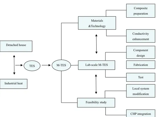
Figure 1.8 Diagram of main scientific work in this thesis ... 11
Figure 2.1 Schematic diagram of the Hotdisk thermal conductivity instrument ... 15
Figure 2.2 Experimental instruments for heat storage and release test ... 16
Figure 2.3 DSC curves of various pure PEG during the heating process ... 16
Figure 2.4 DSC curves of various pure PEG with during the freezing process ... 16
Figure 2.5 (a) Reaction instrument; (b) Vacuum dryer; (c) Shaping instrument; (d) Samples ... 18
Figure 2.6 DSC curves of PEG/SiO2 with different mass ratios during the heating process ... 19
Figure 2.7 DSC curves of PEG/SiO2 with different mass ratios during the freezing process ... 19
Figure 2.8 POM photos of pure PEG during the heating and freezing processes (X200): (a) 25° C (heating process), (b) 60° C (heating process), (c) 64° C (heating process), (d) 68° C (cooling process), (e) 54° C (cooling process) and (f) 25° C (cooling process) ... 20
Figure 2.9 POM photos of pure PEG during the heating and freezing processes (X100): (a) 25° C (heating process), (b) 60° C (heating process), (c) 64° C (heating process), (d) 120° C (heating process), (e) 54° C (cooling process) and (f) 25° C (cooling process) ... 21
Figure 2.10 TG curves of pure PEG, SiO2 and composites ... 22
Figure 2.11 DSC curves of the TES composites under thermal cycles ... 22
Figure 2.12 The structural formula of KH550 ... 24
Figure 2.13 Proposed schematic of modification mechanism for KH550: (a) Hydrolysis of KH550; (b) modification of AlN ... 24
Figure 2.14 The structural formula of the NDZ-401 coupling agent ... 24
Figure 2.15 Proposed schematic of modification mechanism for NDZ-401 ... 25
Figure 2.16 The photos of AlN aqueous suspension before and after modification ... 25
Figure 2.17 Effect of agent amount on AlN modification: (a) KH550; (b) NDZ-401 ... 26
Figure 2.19 Comparison of the PH values of modified AlN aqueous suspensions using various coupling agents ... 27
Figure 2.20 Effect of added AlN amount on thermal conductivity ... 28
Figure 3.1 Setup of oil-bath based thermal test ... 31
Figure 3.2 Sketch of the direct-contact M-TES system ... 32
Figure 3.3 Photos of the experimental facility built at MdH ... 33
Figure 3.4 Tests of repeated heat storage and release cycles ... 34
Figure 4.1 Location of heat supplier and end-user ... 39
Figure 4.2 Scheme of the existing and modified heat supply system in Ärla ... 40
Figure 4.4 Effect of steam-extracting options on the CHP plant including: (a) power output, (b) heat output, (c) steam-extracting flow rate and (d) income of electricity and heat production ... 44
XI
Table 1.1 Energy density comparison of hot water and PCMs ... 3
Table 1.2 Comparison of organic and inorganic PCMs [13, 15, 20, 24-26] ... 4
Table 1.3 Demonstrations of the M-TES system in Japan [82] ... 9
Table 2.1 Characteristics of the experimental materials ... 13
Table 2.2 Information of the experimental instruments and testing devices ... 14
Table 2.3 Measured thermal properties of pure PEG with different molecular weights ... 17
Table 2.4 Measured thermal properties of the composite materials... 19
Table 2.5 Measured thermal properties of the composite materials under thermal cycles ... 23
Table 2.6 Comparison of modified PEG/SiO2 (AlN=15wt. %) and PEG/EG composites ... 28
Table 3.1 Comparison of the charging processes at different flow rates of oil ... 35
Table 3.2 Comparison of the discharging processes at different flow rates of oil ... 36
Table 4.1 Local heat supply with different scenarios... 42
XIII
Nomenclature:
Cp specific heat (kJ/kgC)
ΔHm latent heat of fusion (kJ/kg)
ΔHf latent heat of freezing (kJ/kg)
M quantity of the materials (kg) Tm melting temperature (C)
Tf freezing temperature (C)
Q total heat capacity of a lorry (MWh) Cp specific heat (kJ/kg C) Qm enthalpy (kJ/kg) Ti initial temperature (C) Tf maximum temperature (C) de density (kg/m3) Rn revenue of period n (€) Cn cost of period n (€) n year Io initial investment (€) i discount rate
Qoil,in energy of inlet oil (kWh) Qoil,out energy of outlet oil (kWh) Qs,pcm sensible energy of PCM (kWh) Ql,pcm latent energy of PCM (kWh) Qoil,cont energy of oil in the container (kWh) Qloss energy loss (kWh)
Moil quality of oil (kg)
Cpoil specific heat of oil (kJ/kg °C) Toil,in temperature of inlet (°C) Toil,out temperature of outlet (°C) Ki thermal conductivity (W/m °C) Scont areas of surface of the container (m2) Twall temperature of the container wall (°C) Troom room temperature (°C)
Thins thickness of the insulation (m)
Abbreviations:
AlN Aluminum nitride CHP Combined heat and power DH District heating
DSC Differential scanning calorimeter EEM Eskilstuna Energi och Miljö AB EG Expanded graphite
FT-IR Fourier transformation infrared spectroscope HTO Heat transfer oil
IRR Internal rate of return LTES Latent thermal energy storage M-TES Mobilized thermal energy storage NPV Net present value
PCMs Phase change materials PEG Polyethylene glycol pH Pondus hydrogenii
POM Polarizing optical microscope PP Payback period
POM Polarizing optical microscope SEM Scanning electronic microscope SES Sensible energy storage SG Silica gel
SiO2 Silicon dioxide
TES Thermal energy storage TMA Thermal Mechanism Analysis TG Thermogravimetric analyzer TPS Transient plane source XRD X-ray single crystal diffraction
1
1. Introduction
1.1 Background
1.1.1 Current status of energy consumption and heat supply in Sweden
z Energy use in Sweden
In 2008, total energy use in Sweden amounted to 612 TWh. Of this, total final energy use across three critical sectors made up 397 TWh (Figure 1.1), a 34% increase since 1970 [1].
Figure 1.1 Use of energy in Sweden 2008 (TWh) [1]
In the residential and service sector, energy use reached 141 TWh, accounting for 36 % of the total final energy use. Electricity and district heating are the primary energy consumers in this sector. More than half their supply—78.2 TWh—was consumed for space heating and domestic hot water usage in 2008 [2]. Of this, 31.8 TWh (41%) were used in detached buildings, 25.2 TWh (32%) in multi-dwelling buildings, and 21.2 TWh (27%) in nonresidential buildings. Energy use in the industry sector accounted for 151 TWh, about 38% of the final energy use. The main energy carriers in industry are electricity (35%) and biofuels (37%), complemented by energy from fossil sources (25%). [Fossil energy was provided by 16 TWh of oil products, 16.4 TWh of coal and coke, and 5.4 TWh of natural gas.][1].
z Heat supply in detached buildings and sparse areas in Sweden
Mobilized thermal energy storage for heat recovery for distributed heating
2008, there were about 4.5 million dwellings, 40 % more than in 1970. More than half the Swedish population (56%) lives in detached houses [1]. As of 2007, there were 1.74 million detached houses in use, of which 183,000 were located in farmlands. One third of these were built between 1941 and 1970, and another third between 1971 and 1990. Those built during the early stage are typically equipped with a boiler heating system located in the basement. The houses built later are mostly heated with electricity, either directly with resistance heaters or with an electrical boiler heating system; these houses usually have no basement, boiler room, or chimney [3].
Figure 1.2 Heat supply alternation for space heating and hot water in detached houses in Sweden 2008 (totally 31.8 TWh/y) [4]
Figure 1.2 shows that about 10% of the detached buildings were heated by district heating, 15% were heated by biofuels, and 14% were heated by oil. Electricity represents 13% of the total heat supply exclusively, and 21% when combined with other sources. The most common way of heating in detached houses is with electric heating. Of these dwellings, over half have direct electric heating, and the rest use waterborne electric heating. The main reasons for the high proportion of electric heating are that it is cheap to install and simple to operate. In 2007, the total use of electricity for space heating and domestic hot water production in detached houses was 13.7 TWh.
Although the price of electricity in Sweden has historically been low compared to other European countries, it is gradually approaching the European level. Moreover, high electricity consumption increases the production demand on Sweden’s power plants, especially during the high peak load in the cold winter. Finally, Figure 1.2 also indicates that oil shares 14% of the total heat need of detached buildings. The high price of oil and pollution from the oil combustion are pushing people to search for a clean, sustainable heat supply technology. At present, the Swedish government is promoting a subsidy program for the conversion of electric and oil heating systems. All these factors indicate that there is a huge potential for the conversion of the existing heating system.
13% 21% 14% 15% 4% 11% 10% 12%
Electricity
Electricity with others
oil
biofuel
Heat pump
Heat pump with others
district heating
others
3
1.1.2 Advantages of TES technology for distributed heating
According to the reports on Swedish energy consumption, residential heat demand accounts for a large portion of the total heat consumption, including space heating and hot tap water usage, especially during winter. In the population-dense regions, heat is delivered efficiently by the district heating (DH) network, connecting to centre heating systems or combined heat and power (CHP) plants. However, plenty of detached buildings such as schools and office buildings as well as sparse areas with only a couple of houses are not connected to the DH system. Heat demand for these is usually covered by small-scale heaters such as pellet or electrical boilers, or by a small local heat supply centres usually consisting of biomass or fossil fuel boilers. Fossil fuel is quite costly and produces greenhouse gases (GHGs), specifically carbon dioxide emissions. Meanwhile, abundant waste or excess heat is produced by industrial plants, which creates potential for the recovery of that lost industrial heat. Clearly, it would be of significant importance to find a feasible and economic way to transport the excess industrial heat to detached buildings and sparse areas.
There are two options for transporting industrial heat to end users. One is to build a new pipe network connecting plants and users; this has been discussed and the concerns mainly focus on decreasing the investment cost of the infrastructure construction [5-12]. However, given the small heat demand of distributed users, this method is not economically feasible. The second is to transport heat using a tank filled with hot water or phase change materials (PCMs). Table 1.1 indicates that energy density plays a key role in heat transportation. Hot water has a low energy density and a high transport cost, and hence it is only suitable for transport across a short distance. By comparison, PCMs have large energy densities because they take advantage of additional latent heat during the phase transition. Thus PCMs offer a solution for delivering heat economically over a long distance between the industrial plants and the end users.
Table 1.1 Energy density comparison of hot water and PCMs Storage materials
Energy density
(50-100 0C) (26 tone/lorry, 10km distance) Cost of transportation Distance (26 tone/lorry)
(kWh/tone) Euro cent /kWh km
Hot water 50 3.9 15
PCMs 100~130 1.4~1.9 30
*1 Euro = 10.491 Kr
1.1.3 State of the art on thermal energy storage materials and technology
Latent thermal energy storage (TES) is attractive due to its large energy storage density and its ability to store and release heat at a constant temperature corresponding to the phase change temperature. PCMs can be grouped as inorganic and organic compounds. Inorganic compounds include salt hydrates, salts metals and alloys, etc., while organic compounds consist of paraffin, non-paraffin, fatty acids, etc. [13-17] .
Mobilized thermal energy storage for heat recovery for distributed heating
The prospective energy storage materials should have the following characters for actual application [17, 18]:
z large latent heat and high thermal conductivities;
z variable operation temperatures to accommodate different practical applications; z thermal stability for a long-term use;
z non-toxic, non-corrosive and non-explosive qualities; z low prices and large availability.
A comparison of organic and inorganic materials can be seen in Table 1.2. Most organic PCMs are non-corrosive, thermal stable, exhibit little or no sub-cooling and are compatible with most building materials, in addition to having a high latent heat per unit weight with low vapor pressure. Their disadvantages are low thermal conductivity, high changes in volume on phase change, and flammability. Inorganic materials have a high latent heat per unit volume and high thermal conductivity, and they are non-flammable and low cost compared to organics. However, they are corrosive to most metals and suffer from decomposition and serious sub-cooling, which can affect their phase change properties. The applications of inorganic PCMs require the use of nucleating and thickening agents to minimize sub-cooling and phase separation [19-23].
Table 1.2 Comparison of organic and inorganic PCMs [13, 15, 20, 24-26] Advantages Disadvantages Organic
z No corrosives
z Low or none sub-cooling z Chemical and thermal stability z Volume change
z Lower phase change enthalpy z Low thermal conductivity z Flammability
Inorganic
z Greater phase change enthalpy z High heat transfer rate z Inflammability
z Sub-cooling z Corrosion z Phase separation z Lack of thermal stability
The significant TES applications can be divided into two groups: heat and cool thermal storage. These include solar energy storage [27-32], power peak shift [33-38], food and medicine protection and preservation [39-42], passive energy storage in architecture [43-48], electric device cooling[49-52], thermal cooling supply [53-55], etc. Until now, most work has focused on the development of new TES materials and composites as well as heat transfer enhancement in application. A form-stable composite has been developed without any leakage and volume change during the phase transition, which extends the use of PCMs for specific applications and simultaneously decreases the cost for encapsulation of the transport vessel [26, 56-63]. The
5
enhancement of heat transfer in PCM applications is of significance regarding the thermal conductivity of PCMs and the design structure of TES facilities [64-73].
1.1.4 State of the art on mobilized thermal energy system
z Concept of the M-TES system
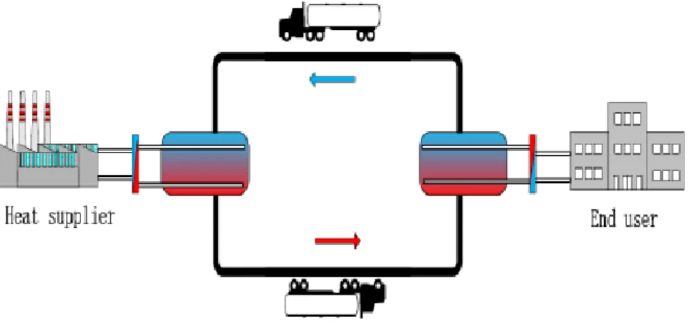
The mobilized thermal energy storage (M-TES) system, illustrated in Figure 1.3, is an energy transportation method using high energy-dense technology. This system has the potential to meet the heating demand of detached buildings and sparse areas, including use in combination with other heat supply systems, and can reduce greenhouse gas emissions by replacing fossil-based heat sources in addition to saving high-grade electricity energy. The M-TES system consists of a thermal energy storage container, a heat exchanger for charging and discharging stations, a pump and a lorry. In it, TES materials play a key role in storing and releasing heat during the charging and discharging processes. A heat transfer oil (HTO) or water serves as a heat transfer medium for transferring heat from heat sources to end users [74-80].
Figure 1.3 Diagram of mobilized thermal energy storage system
Two types of TES containers have been designed based on different heat transfer mechanisms. One is the direct-contact TES container, in which TES material is mixed directly with a heat transfer medium. Hence, the PCM is required to be non-soluble in the transfer medium, and a large density difference between them is necessary to separate them from each other. In Germany, the TransHeat Company uses a direct-contact TES container (Figure 1.4). A heat transfer medium is pumped into the TES container through pipes to heat and melt the PCMs. In this dynamic charging process, direct contact between the PCMs and the transfer media results in a strong heat transfer performance. The thermal storage system has both sensible heat of the PCMs and the transfer media as well as the latent heat of the PCM. Finally, the heat transfer medium rises from the top pipes due to the density difference. The second type of containers is the indirect-contact TES container. It has an immersed heat exchanger, where heat transfer medium passes through the
Mobilized thermal energy storage for heat recovery for distributed heating
pipe’s interior and transfers heat to the TES materials. In this way, the heat transfer rate depends on the contact surface areas and the thermal conductivity of the PCM. In contrast, the direct-contact TES container has a higher heat transfer rate than the indirect-contact unit. Larger heat transfer rate could be gained by immersed heat exchanger design and modification of PCM. Figure 1.5 shows the TES container developed by the Alfred Schneider Company (also in Germany).
Figure 1.4 Direct-contact TES container based M-TES system, TransHeat, Germany [77]
Figure 1.5 Indirect-contact TES container based M-TES system, Alfred Schneider, Germany [74] z Research and applications on M-TES system
In Sweden, Climate Well has developed a direct-contact TES system (Figure 1.6). Two storage tanks contain salt hydrate (thermal energy storage material) and water, separately. Both tanks are connected to each other by a pipe on the top. In the charging process, salt hydrate is heated and crystal water is released and evaporates, moving to the water tank. Thus, heat is stored in the salt container. In the discharging process, water evaporates from the water tank and is absorbed in the
7
salt tank. Heat can be released by recombining salt and crystal water. Moreover, to improve the performance of this system, air is extracted from the tank, reportedly increasing the water transport speed [81].
Figure 1.6 Thermal energy storage system developed by Climate Well [81]
In Germany, TransHeat Company uses a commercial M-TES system which is characterized by the direct-contact heat transfer technique. Two inorganic materials have been selected and developed as potential TES material candidates for different users; these are barium hydroxide (BaH2O2·8H2O) and sodium acetate trihydrate (CH3COONa·3H2O). Another M-TES system is
used by the Alfred Schneider Company, whose TES container is designed with immersed heat exchanger. At present, there is no report available about the practical applications or demonstrations for this type of M-TES system. However, in Japan, some institutes are also working in this field and have developed a container based on a prototype of TransHeat’s technique[76].
The earliest practical application of these systems was reported to be implemented in Germany. LSG Sky Chefs (Neu-Isenberg) must be recognized for its efforts to introduce innovative technology related to environment protection, and TransHeat contributed technique design and support for this effort [75]. The waste heat came from a power station, where generated process heat needed to be cooled down. Barium hydroxide was used as the energy storage medium. A truck provided 25 m3 of materials storing heat to LSG, and one container was found to store 4
MWh of heat—equal to 450 l of heating oil. At LSG, the water was used in kitchens and dishwashing facilities.
Mobilized thermal energy storage for heat recovery for distributed heating
Figure 1.7 Demonstration of the M-TES application at LSG Sky Chefs in Cologne [75] Another case in Germany involved the transport of heat to a school over a 10-km distance from a biomass power plant. The heat demand was approximately 1850 MWh per year, covered by a local oil boiler with an efficiency of 85%. In the modification of the existing system, transported heat became responsible for the base load heat demand, and the oil boiler was left as a backup for the peak demand. The heat transport technology was also from TransHeat, and sodium acetate trihydrate served as the storage material [76].
Three M-TES demonstrations have been implemented in Japan (Table 1.3). In Demonstration I, heat was delivered over 20 km between two factories. The purpose was to preheat feed water for a boiler in another factory, decreasing energy consumption and cost. Meanwhile, the heat was derived from (free) excess heat generated by an electric company, which decreased the operating cost to make it more economical and feasible. In Demonstrations II and III, the M-TES system supplied higher temperature heat, which can be used widely among residential or industrial end users. Moreover, it also can be used to drive absorption chillers to supply absorption cooling; this means that the M-TES system has significant potential in the heating and cooling supply market [82].
9
Table 1.3 Demonstrations of the M-TES system in Japan [82]
Descriptions Demonstration I Demonstration II Demonstration III Heat source Factory of SANYO Electric Co. Ltd. in Gunma Sewage plant in Kiyose-city Tokyo Kagaya factory of KURIMOTO, LTD in Osaka city End user Factory of Furukawa Sky Aluminum Corp. in Saitama
Civic gymnasium Sumiyoshi factory
Distance 20 km 2.5 km 3 km
Usage Preheat feeding water to a boiler
Supply of hot water to the absorption chiller generating cool water to air condition
Heat water for the bath of employees
Heat type Excess steam heat Waste gas form sludge incinerator
Waste gas from annealing furnace
Other info. N.A. N.A.
Container is a small one with 5 m3 and the
storage capacity is about 415kWh
1.2 Problems of delivering industrial heat to distributed users
To transport industrial heat to distributed users, an effective system with a high heat density should be developed—one which is also simple to build and easy to run. It is not economically feasible to transport hot water by building a pipe network. It is not possible to transport hot water by a lorry over a long distance due to its low heat density. Because PCM-based LTES materials have large heat densities, usually 2 or 3 times that of the sensible heat of water, the M-TES system has been based on TES technology for heat transportation. In the M-TES system, TES materials and the structure of storage containers play a key role in the performance of the system. Meanwhile, inorganic materials used in the current M-TES system are not promising due to their low thermal stability caused by severe sub-cooling and phase separation; furthermore, they are also toxic and corrosive, resulting in strict requirements on container capsulation and fabrication materials. It may be instructive to develop M-TES system using organic PCMs. However, they have low thermal conductivities, especially when used in the indirect-contact TES containers, resulting in low heat transfer rates. The problems can be resolved from two aspects. One is to develop a new type of TES material with a large heat density and high thermal conductivity. The other is to develop direct-contact TES containers using organic materials. Thermal behavior and the performance of direct-contact TES containers during the charging and discharging processes require more investigation.
1.3 Objectives of this work
Mobilized thermal energy storage for heat recovery for distributed heating
waste or excess heat for use in distributed heating. This work has three goals: (1) design and investigate new form-stable TES composites for thermal conductivity enhancement, and find new suitable types of composites for indirect-contact containers; (2) investigate the thermal behavior and performance of direct-contact TES containers based on our newly designed and built lab-scale M-TES system; and (3) conduct and analyze a technical and economic feasibility study to evaluate the M-TES system. In addition, the heat charging options and the effect of the steam-extracting on the CHP plant are discussed in this work.
1.4 Methods
An analysis of both the existing heat supply systems for detached houses/sparse areas and thermal energy storage technology was the starting point for this study. Based on a survey of current heat supply measures and previous work, it was decided to develop a new heat transport system using PCM-based LTES technology to deliver industrial heat to end users.
Thermal energy storage technology plays a key role in the transport system, and hence the thermophysical properties of various phase change materials were studied to determine their potential; these included the phase transition melting and freezing temperatures, the latent heat capacity, the thermal stability, and phase change behaviors. On the basis of knowledge about PCM materials, the new form-stable PEG-based TES composites were prepared using different mechanisms and methods. Investigation of the properties of PCM materials and composites included the use of a scanning electronic microscope (SEM), a Fourier transformation infrared spectroscope (FTIR), a polarizing optical microscope (POM) and dynamic mechanic analysis (DMA). In addition, thermal conductivity enhancement was investigated because of the low thermal conductivities of organic PCM materials. Two methods were used, mixing high thermal conductivity additives and absorbing PCMs in the high thermal conductivity matrix.
Based on the existing heat supply for detached houses, a mobilized thermal energy storage (M-TES) system was developed using TES technology. A lab-scale of the M-TES system was designed, built and tested. In the experiments, the phase change behavior of the PCM materials was observed. Measurements were made of different flow rates of oil in the charging and discharging processes.
Simultaneously, a case study in Ärla, a small region in the Eskilstuna municipality in Sweden, was conducted using this new concept. In it, the combination of the M-TES and a locally existing pellet boiler system were used to replace an oil boiler system. A technical analysis was made to investigate the operating conditions of the modified heat supply system. The heat source of the combined heat and power plant and the different methods of extracting heat from the steam cycle in the power plant were studied via simulation using ASPEN software. The M-TES system was analyzed with respect to investment and operation cost. The existing and modified systems were compared in regard to cost distribution and relative heat cost. An economic analysis of the modified heat supply system was evaluated. Finally, a sensitivity study was conducted to investigate the impact of different parameters on the economic feasibility of the modified heat supply system.
11
Figure 1.8 Diagram of main scientific work in this thesis
1.5 Thesis outline
This thesis is composed of three main parts, combining several research papers. Papers I, II, and III focus on the preparation and investigation of the new form-stable composites with high thermal conductivity. In Paper VI, the M-TES system was studied experimentally on the performance of lab-scale facility. In Papers IV and V, the feasibility of M-TES system for a modified heat supply is discussed. The outline of this thesis is as follows:
Chapter 1: Present the background of this thesis, including data on heat consumption in Sweden, the state-of-the-art of TES materials and technology, and the M-TES system. Propose problems in this research field and determine the objective of this thesis is to fix these problems scientifically. Chapter 2: Present the preparation and investigation of two form-stable composites.
Chapter 3: Present the experiments of the lab-scale M-TES system and the investigation of the thermal behavior and performance of the direct-contact TES container.
Materials &Technology Component design Fabrication Feasibility study Industrial heat Detached house
M-TES Lab-scale M-TES
TES Test Composite preparation Conductivity enhancement Local system modification CHP integration
Mobilized thermal energy storage for heat recovery for distributed heating
Chapter 4: Provide a feasibility analysis based on a case study of the M-TES system for the modified heat supply.
Chapter 5: Draw conclusions.
13
2. Design, modification and analysis of thermal energy storage
materials
Due to a low heat transfer rate in indirect-contact TES containers, TES materials need to be modified for improved thermal conductivities with reasonable thermal enthalpy. In this chapter, TES composites were prepared and studied to develop a new type of composite that can be used in an indirect-contact container. This chapter is based on Papers I, II and III.
2.1 Experiments
2.1.1 Materials and instruments
The materials and instruments used in the following experiments are described in Tables 2.1 and 2.2. Polyethylene glycol (PEG) is a substance having many applications in industrial manufacturing and in the field of medicine. PEG is prepared by polymerization of ethylene oxide. It is commercially available at different melting temperatures corresponding to a wide range of molecular weights. For this experiment, PEG (molecular weight from 800 to 10,000) was selected. The structure of PEG is HO-CH2-(CH2-O-CH2-)n-CH2-OH. Silica gel and expandable graphite are
also commercially available. They are used as the supporting material and matrix in the composites, respectively. β-Aluminum nitride (β-AlN) is a commercial grade element that was selected to enhance thermal conductivity of TES composites; it was first modified by a commercial coupling agent composed of silane (KH550) and titanic acid ester (NDZ-401). Thus, all the materials and agents needed are available in the commercial market, which keeps the cost of material production low both now and in the future. All the instruments and measurement devices in Table 2.2 are available in the laboratory and testing centre.
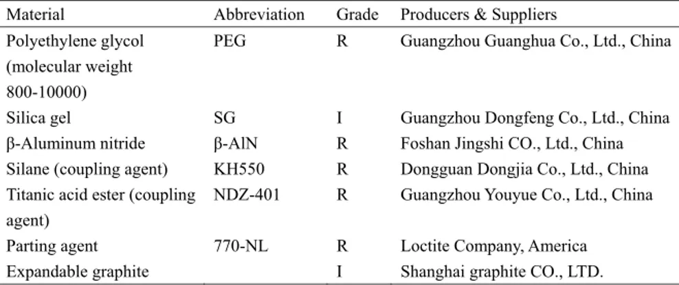
Table 2.1 Characteristics of the experimental materials
Material Abbreviation Grade Producers & Suppliers Polyethylene glycol
(molecular weight 800-10000)
PEG R Guangzhou Guanghua Co., Ltd., China
Silica gel SG I Guangzhou Dongfeng Co., Ltd., China β-Aluminum nitride β-AlN R Foshan Jingshi CO., Ltd., China Silane (coupling agent) KH550 R Dongguan Dongjia Co., Ltd., China Titanic acid ester (coupling
agent)
NDZ-401 R Guangzhou Youyue Co., Ltd., China Parting agent 770-NL R Loctite Company, America Expandable graphite I Shanghai graphite CO., LTD.
Mobilized thermal energy storage for heat recovery for distributed heating
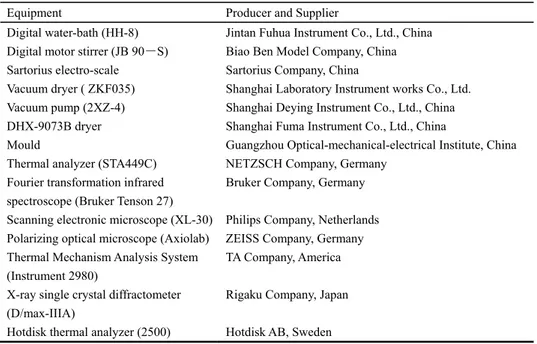
Table 2.2 Information of the experimental instruments and testing devices Equipment Producer and Supplier
Digital water-bath (HH-8) Jintan Fuhua Instrument Co., Ltd., China Digital motor stirrer (JB 90-S) Biao Ben Model Company, China Sartorius electro-scale Sartorius Company, China
Vacuum dryer ( ZKF035) Shanghai Laboratory Instrument works Co., Ltd. Vacuum pump (2XZ-4) Shanghai Deying Instrument Co., Ltd., China DHX-9073B dryer Shanghai Fuma Instrument Co., Ltd., China
Mould Guangzhou Optical-mechanical-electrical Institute, China Thermal analyzer (STA449C) NETZSCH Company, Germany
Fourier transformation infrared spectroscope (Bruker Tenson 27)
Bruker Company, Germany Scanning electronic microscope (XL-30) Philips Company, Netherlands Polarizing optical microscope (Axiolab) ZEISS Company, Germany Thermal Mechanism Analysis System
(Instrument 2980)
TA Company, America X-ray single crystal diffractometer
(D/max-IIIA)
Hotdisk thermal analyzer (2500)
Rigaku Company, Japan Hotdisk AB, Sweden
2.1.2 Preparation and modification of PCM
PEG was selected for study as an organic PCM. First, PEG/SiO2 was prepared by blending PEG in
silica gel solution. Second, AlN was added into the PEG/SiO2 composites to enhance thermal
conductivity. Third, another PEG/EG composite was prepared by mixing melted PEG with EG. The detailed preparation and conditions can be found in attached papers.
2.1.3 Characterization
z Scanning electronic microscopy (SEM)
The surface morphology of each sample was examined using a scanning electron microscope (Philips Scanning Electron Microscope XL30FEG). Microphotographs were taken of the surface made by fracturing the specimen in liquid nitrogen and then casting it with gold (AU) powder. z Differential scanning calorimetry (DSC)
The melting point and the heat of fusion of the solid composite were determined using a differential scanning calorimeter calibrated with an indium standard in the range from -20 ° C to 120 ° C. The scanning rate was 10° C /min. The temperature accuracy was ±0.01 ° C, and heat flow repeatability was 0.2 μW. The sample (10mg) was sealed in an aluminum pan. The melting and crystallization points were taken as onset temperatures. The latent heat of the PCM was determined by numerical integration of the peak thermal transition area. All DSC measurements were repeated two times for each sample.
15
z Fourier transformation infrared spectroscope (FT-IR)
Fourier transformation infrared spectrum analysis was used to study the functional groups of PCM molecules. In this test, the PCM was melted and formed into a thin film on the surface of a KBr slice, which was used to conduct the FTIR tests.
z Polarizing optical microscopy (POM)
An observation with a polarizing optical microscope was performed on a 12pol microscope equipped with a digital camera. The sample was placed between a microscope glass and a cover slip. z Thermal mechanism analysis system (TMA)
The physical characteristics of the materials were measured using a thermal mechanism analyzer (Instrument 2980, TA). Thermal elongation, expansion, and penetration during the thermal mechanism test applied a constant force at different temperatures and stretching ratios. A constant force of 1 N was applied at a constant heating rate of 5° C /min, with a nitrogen flow rate of 100ml/min, from -30° C to 130° C.
z X-ray single crystal diffraction (XRD)
Samples were spotted with gold to prevent charging. X-ray diffraction was used to investigate the crystalline phase of the composite PCM powders, and XRD patterns of the composite PCMs were recorded in the 2θ range from 5° to 45°. XRD patterns were obtained by means of continuous scanning mode at the rate of 4°/min and operating conditions of 40kv and 100mA.
z Thermogravimetric analyzer (TG)
The thermal stabilities of the materials were evaluated using a thermogravimetric analyzer (NETZSCH STA 449C) under a N2 atmosphere, and the scanning rate was 10° C /min in the
temperature range of 25° C to 700° C. z Thermal conductivity analyzer
The thermal conductivity of the sample was measured by using the transient plane source (TPS) technique at room temperature. Figure 2.1 shows the schematic diagram of the Hotdisk thermal conductivity instrument. The sensor needs to be placed between two identical samples. The samples should be tightened for good contact with the sensor.
Figure 2.1 Schematic diagram of the Hotdisk thermal conductivity instrument z Experiments on heat storage and release performance
Mobilized thermal energy storage for heat recovery for distributed heating
Figure 2.2 shows the experimental instrument for the heat storage and release test. Phase change material and the composites were put into two identical tubes. One thermocouple was placed in the middle of each tube. First, the two test tubes were put in the water at room temperature. Next, the two tubes were put into a water bath at the constant temperature. After the sample reached the designed temperature, the two tubes were put into the water at the same temperature again. The temperature measured by the thermocouple was recorded automatically using an Agilent data acquisition instrument.
Figure 2.2 Experimental instruments for heat storage and release test
2.2 Thermal performance of organic thermal energy storage materials
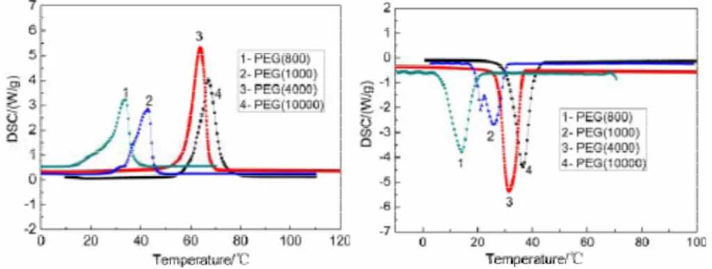
First, thermal properties of PEG were measured by DSC calorimetry. The DSC curves for PEG are illustrated in Figures 2.3 and 2.4, respectively, and the detailed thermal properties are also presented in Table 2.3.
Figure 2.3 DSC curves of various pure PEG during the heating process
Figure 2.4 DSC curves of various pure PEG with during the freezing process
17
Table 2.3 Measured thermal properties of pure PEG with different molecular weights
PEG Thermal properties
Tm (° C) ΔHm (kJ/kg) Tf (° C) ΔHf (kJ/kg)
PEG(10000) 61.1 187.3 49.5 142.1
PEG(4000) 57.7 186.7 36.3 152.2
PEG(1000) 32.9 173.4 30.1 154.3
PEG(800) 28.5 137.3 14.2 129.8
Figures 2.3 and 2.4 and Table 2.3 indicate that the latent heat of pure PEG with different molecular weights (800, 1000, 4000, 10000) ranged from 137.3 kJ/kg to 187.3 kJ/kg. The latent heat of PEG increased with the increase of molecular weights, proving that PEG has a large latent heat. From Table 2.3, it can be seen that the melting and freezing temperatures varied from 28.5° C to 61.1° C in the heating process, and from 14.2° C to 49.5° C in the freezing process for different molecular weights of PEG. The large range of melting temperatures makes it possible to use PEG in different applications.
2.3 Thermal properties of form-stable TES composites
2.3.1 Preparation of TES composites
Form-stable composites of PEG/SiO2 were prepared with different component ratios to investigate
the maximum weight percentage of PEG in the composite. Figures 2.5 (a)-(c) show the photos of the main experimental devices used in the composite material preparation. Figure 2.5 (d) shows the samples that were made in the experiments.
Mobilized thermal energy storage for heat recovery for distributed heating
Figure 2.5 (a) Reaction instrument; (b) Vacuum dryer; (c) Shaping instrument; (d) Samples
2.3.2 Thermal property investigation
z Thermal enthalpy analysis
From Figures 2.6 and 2.7 and Table 2.4, it can be seen that the enthalpy of the compositesdecreased with the diminution of the weight percentage of PEG. Moreover, comparedto the measured latent heat of the composite PCMs with the calculated value, it was found that the measured values were slightly lowerthan the calculated ones. This was because SiO2 kept quite stable in the phase
transition of PEG. Therefore, SiO2 can be considered as an impurity in PEG affecting the perfection
of the crystallization process. In addition, the melting and crystallizing temperatures had exhibited no significant change. Table 2.4 shows that compared to pure PEG, the change in melting temperature of the composite materials rangeed from 0.43- 4.58° C, and the changes in freezing temperature were 1.16- 3.46° C. These changes were not significant for the practical application.
19
Figure 2.6 DSC curves of PEG/SiO2 with
different mass ratios during the heating process
Figure 2.7 DSC curves of PEG/SiO2 with
different mass ratios during the freezing process Table 2.4 Measured thermal properties of the composite materials
Composite Materials Thermal properties Tm (℃) ΔHm (kJ/kg) Tf (℃) ΔHf (kJ/kg) PEG(85wt. %)/SiO2 61.61 162.9 48.36 124.2 PEG(70wt. %)/SiO2 60.85 129.5 47.25 98.4 PEG(60wt. %)/SiO2 60.32 108.7 47.64 68.3 PEG(50wt. %)/SiO2 56.60 86.5 46.06 38.5
z Phase change behavior analysis
From Figure 2.8(a), it can be seen that pure PEG was crystalline and its crystal structure was orbicular at 25° C. This indicates that polyethylene glycol had a good crystalline capacity, which contributed to the reasonable latent heat. When the temperature reached 64℃ in the heating process, the color became faint and parts of the crystal structure disappeared. This was because parts of PEG started to melt and the crystal structure was consequently damaged. No color light appears in Figure 2.8(c). This indicates that the entire quantity of PEG was almost melted completely at 68° C. In other words, the phase change process was finished at this point. The whole process occurred quickly, indicating that PEG has a narrow melting temperature range from 60° C to 68° C. The results were in good agreement with the results of the DSC analysis. In the freezing process, when the temperature dropped down to 54° C, the crystalline light reappeared. Compared to the photo at the same temperature during the heating process (Figure 2.8 (b)), the color turned lighter. The same observations can be found in the photo image when temperature dropped to 25℃. The results show that PEG has a sub-cooling problem and its crystal structure cannot be recovered completely.
Mobilized thermal energy storage for heat recovery for distributed heating
(a) 25° C (heating process) (b) 60° C (heating process) (c) 64° C (heating process)
(d) 68° C (cooling process) (e) 54° C (cooling process) (f) 25° C(cooling process) Figure 2.8 POM photos of pure PEG during the heating and freezing processes (X200): (a) 25° C
(heating process), (b) 60° C (heating process), (c) 64° C (heating process), (d) 68° C (cooling process), (e) 54° C (cooling process) and (f) 25° C (cooling process)
Figure 2.9(a) shows the POM photo image of the composite material at 25° C. Unlike the pure PEG, the orbicular shape of the crystal structure cannot be observed in the composite materials due to the limitation of the supporting materials. However, the colored lights representing the PEG crystalline can still be seen in the photo. With the temperature rising, the color becomes faint. The POM micrograph of the composite PCMs at 120° C is shown in Figure 2.9(d). At this point, all the light has disappeared and solid particles can still be found in this last stage. This indicates that SiO2,
serving as a supporting material, helped prevent leakage of the melted polyethylene glycol. This solid–solid phase-change behavior of the composite is further confirmed by visual observation. When the composite was slowly heated to 120° C, it was observed that liquid leakage did not occur during the process. In the freezing process, the color reappeared but was lighter than it was at 25° C.
21
(a) 25° C(heating process) (b) 60° C (heating process) (c) 64° C (heating process)
(d) 120° C (heating process) (e) 54° C (cooling process) (f) 25° C (cooling process) Figure 2.9 POM photos of pure PEG during the heating and freezing processes (X100): (a) 25° C
(heating process), (b) 60° C (heating process), (c) 64° C (heating process), (d) 120° C (heating process), (e) 54° C (cooling process) and (f) 25° C (cooling process)
z Thermal stability analysis
Figure 2.10 illustrates TG results of the SiO2, PEG, and PEG/SiO2 composites, respectively. From
the figure, it can be seen that the supporting material, SiO2, was quite stable during the measuring
temperature range from 0° C to 800° C. No mass losses occurred in it during the heating process. In contrast, pure PEG lost its weight starting at 227° C. When the temperature reached 358° C., there was almost nothing left of PEG, which means that it combusted and decomposed completely before that point. Hence, PEG can be used safely below a temperature of 227° C. For the composite materials, the curves show that the weight loss occurred at 300° C as the PEG in the composite started to vanish. Up to 310° C, the mass fraction did not change. PEG mass fractions in the two composites can be obtained at 82.7 wt. % and 84.5 wt. %, respectively.
Mobilized thermal energy storage for heat recovery for distributed heating
Figure 2.10 TG curves of pure PEG, SiO2 and composites
z Thermal cycle tests
In this experiment, the composite material at PEG mass proportion of 85 wt.% was chosen for testing its stability of thermal performance after 1, 150, and 300 periods of thermal cycling. Figure 2.11 and Table 2.5 show the detailed results of the PEG/SiO2 composites and thermal properties
after repeated thermal cycles. It can be seen that for all cycles, the melting temperatures of composite PCM changed by 0.17° C and 3.18° C, and the freezing temperature changed by 1.62° C and 2.97° C, respectively. It can be seen that the form-stable composite PCM has good thermal reliability in terms of the latent heat. The latent heat of melting changed by 4.1% and 2.7%, while the latent heat of freezing changed by 7.3% and 4.9%, respectively, which indicated that PEG and its composites had a quite good thermal stability.
23
Table 2.5 Measured thermal properties of the composite materials under thermal cycles Cycles Thermal properties of the PEG/SiO2 materials
Tm [° C] ΔHm [kJ/kg] Tf [° C] ΔHf [kJ/kg]
1 61.61 162.9 48.36 124.2
150 60.78 156.2 46.74 116.9
300 58.43 158.5 45.39 118.1
2.4 Enhanced thermal conductivity by AlN modification
2.4.1 Preparation
Due to the hydrolysis of AlN, two coupling agents were selected to modify the surface AlN particles. Different coupling agents were dissolved in different solvents. Ethanol and isopropanol served as solvents for the silane coupling agent (KH550) and NDZ-401 coupling agent, respectively. First, the two coupling agents were dissolved in 100ml of solvent. Then, the solution was added to a three-neck flask connected with a water-condensing unit. Subsequently, 20g of AlN was added to flask and stirred. The flask was heated in a water bath at a given temperature (50, 60 and 70° C) for three hours. After washing and filtering, the powder was dried at 110° C. Finally, 1g of treated powder was taken and put into 50ml water at 60° C. The performance of modification of AlN was conducted by pH measurement. After that, the modified AlN was added during the composite preparation with different ratios, and thermal conductivity was tested using a Hot Disk device.
2.4.2 Mechanism of modification on AlN
z Hydrolysis of AlN Powder
The hydrolysis of AlN can produce aluminum hydroxide and ammonia. The reaction of AlN powder with water at room temperature is illustrated by the following scheme[83-85]:
AlN + 3H2O = AlOOH (amor) + NH3 (1)
NH3 + H2O =NH4+ + OH- (2)
AlOOH + H2O = Al(OH)3 (3)
AlN powder first reacts with water to form amorphous hydroxide (pseudoboehmite, AlOOH). Subsequently, amorphous aluminum hydroxide recrystallizes to bayerite (Al(OH)3 ). Consequently,
this hydrolysis process will damage the thermal conductivity performance of AlN. Therefore, it is necessary to modify the AlN surface to avoid hydrolysis.
z KH550 coupling agent
γ-aminopropyl triethoxy silane, NH2(CH2)Si(OC2H5)3(KH550), was used as a coupling agent to
Mobilized thermal energy storage for heat recovery for distributed heating
N
H2 CH2 CH2 CH2 Si O CH2 CH3
O CH2 CH3
O CH2 CH3
Figure 2.12 The structural formula of KH550
The silane coupling agent undergoes chemical changes during hydrolysis as shown Figure 2.13. When the KH550 meets with water, the SiOC2H5 group transforms to the Si-OH group. Each Si-OH
group in the coupling agent is supposed to react with one hydroxyl group of the β-AlN particle surface and form a covalent bond [86-89].
Si O CH2 CH3 O CH2 CH3 O CH2 CH3 Y
+
3H2O Y Si OH OH OH+
3CH3CH2 OH (a) (b)Figure 2.13 Proposed schematic of modification mechanism for KH550: (a) Hydrolysis of KH550; (b) modification of AlN
z NDZ-401 coupling agent
Another coupling agent used was C44H96O10TiP2 (NDZ-401), and the structural formula of
NDZ-401 can be seen in Figure 2.14. CH3 CH O
C H3
4 Ti O P O C8 H17
O C8H17
2
Figure 2.14 The structural formula of the NDZ-401 coupling agent
The modification mechanism is illustrated in Figure 2.15. It can be seen that the NDZ-401 coupling agent has two different types of groups. One of these is (CH3)2CHO-, which reacts with the
25
Figure 2.15 Proposed schematic of modification mechanism for NDZ-401
2.4.3 Performance of modification on AlN
z Comparison of AlN powder with and without modification
Figures 2.16(a) and (b) show the AlN powder mixed with water before and after modification. Because AlN reacts easily with water, Figure 2.16(a) shows the powder precipitated immediately when it was put into the beaker. In contrast, Figure 2.16(b) shows that the treated powder was quite stable on the surface of water, which was confirmed by pH measurements.
Because of the hydrolysis, a large amount of –OH groups were produced. By measuring the pH value of the suspension, it can be seen that the pH value quickly reached a maximum value of about 10. Consequently, KH550 and NDZ-401 were used to modify the surface of the AlN to prevent its hydrolysis. To test the anti-hydrolysis performance of the modified AlN powder, the pH values of the suspension were measured and compared. If the pH value was small, it indicated that the modified AlN had a good hydrolysis-resistance performance. Some parameters affecting the hydrolysis-resistance performance were also discussed.
(a) Before (b) After
Figure 2.16 The photos of AlN aqueous suspension before and after modification z Effect of the amount of coupling agent
Figures 2.17 (a) and (b) show the effects of two coupling agents on the pH values of the AlN aqueous suspensions. It can be seen in Figure 2.17 (a) that as the mass fraction of the KH550 increased from 1wt.% to 7 wt.%, the pH values decreased, which means the hydrolysis-resistance
Mobilized thermal energy storage for heat recovery for distributed heating
performance of the AlN powder was enhanced. When the mass fraction was 5 wt.%, the pH value of the aqueous suspension was quite stable at around 8.5 for 26 hours. When the mass fraction was as high as 7 wt.%, the pH value of the aqueous suspension was measured at 7.6, without any change during the same time. In contrast, the pH value jumped from 6.5 to 9.5 in five and ten minutes when the mass fraction of KH550 was 1 and 3 wt.%, respectively. This means that the surface of AlN was not completely modified. Therefore, for KH550, the optimum mass fraction is 7 wt.% in this experiment. From Figure 2.17 (b), the same trend of mass fraction vs. pH value can also be observed for another coupling agent, NDZ-401. The difference is that for NDZ-401, only more than 2.5 wt.% of the mass fraction can reach a pH-stable aqueous suspension. For the experiment, 3 wt.% of NDZ-401can be considered as the optimum mass fraction.
(a) KH550 (b) NDZ-401
Figure 2.17 Effect of agent amount on AlN modification: (a) KH550; (b) NDZ-401 z Effect of reaction temperature
In this section, the reactions between the coupling agents and AlN were carried out at various temperatures. The results obtained are shown in Figures 2.18 (a) and (b), respectively. It was found that reaction temperature had a stronger impact on KH550 than on NDZ-401. With a rise in temperature from 50° C to 70° C, the pH value decreased with the enhanced anti-hydrolysis performance of modified AlN. Therefore, in this experiment, 70° C is recommended as the appropriate reaction temperature.
27
(a) (b)
Figure 2.18 Effect of reaction temperature on the AlN modification: (a) KH550; (b) NDZ-401 z Comparison of various coupling agents
Testing the optimum operation condition for each coupling agent, KH550 (7 wt. %, 70° C) and NDZ-401 (3 wt. %, 60° C), the results are compared and shown in Figure 2.19. Compared with an unmodified AlN aqueous suspension, both agents definitely contributed to the enhancement of anti-hydrolysis performance. According to the pH values of the stable suspensions, NDZ-401 produced a better modification on AlN.
Figure 2.19 Comparison of the PH values of modified AlN aqueous suspensions using various coupling agents
2.4.4 Thermal conductivity enhancement and analysis
Thermal conductivities of the composite PCMs were improved by using β-Aluminum nitride additive as a heat transfer promoter due to its high thermal conductivity. The conductivities increased with the increase of the AlN mass proportion. However, latent heat decreased after
Mobilized thermal energy storage for heat recovery for distributed heating
adding AlN powder in the composite. The optimal AlN weight percentage is 15% with the consideration of both thermal conductivity and heat capacity.
Figure 2.20 Effect of added AlN amount on thermal conductivity
2.5 Comparison of AlN-modified PEG/SiO
2and PEG/EG
Two types of the TES composites were prepared using physical methods, and most of their thermal performance was similar. Hence, the results and analysis are not presented in this thesis. A comparison of the two composites is described in Table 2.6.
Two types of composite materials were prepared in two different ways. AlN-modified PEG/SiO2
was prepared by blending two components in an aqueous solution and modified by adding AlN power. PEG/EG was prepared by mixing melted PEG and EG together. In a comparison of the two methods, the preparation process of the PEG/EG took less time than the modified PEG/SiO2. Both
composites were easy and simple to prepare. The PEG/EG composite had quite a high thermal conductivity (1.324 W/m K) in comparison to the modified PEG/SiO2, which would have a strong
affect on heat transfer in practical applications.
Table 2.6 Comparison of modified PEG/SiO2 (AlN=15wt. %) and PEG/EG composites Descriptions Modified PEG/SiO2 (AlN=15wt. %) PEG/EG
Materials PEG and Silica gel (AlN additive) PEG and expandable graphite Reaction Category Physical method Physical method
Preparation methods Blend PEG with silica gel and AlN in aqueous solution, and then dried.
Melted PEG mixed with EG Preparation time More than 27 hours Around 3 hours
Maximum latent heat Approx. 137.7 kJ/kg Approx. 161.2 kJ/kg Melting temperature 60.4 ° C 61.46 ° C
![Figure 1.1 Use of energy in Sweden 2008 (TWh) [1]](https://thumb-eu.123doks.com/thumbv2/5dokorg/4914270.135297/19.718.135.618.371.637/figure-use-energy-sweden-twh.webp)
![Figure 1.2 Heat supply alternation for space heating and hot water in detached houses in Sweden 2008 (totally 31.8 TWh/y) [4]](https://thumb-eu.123doks.com/thumbv2/5dokorg/4914270.135297/20.718.138.580.258.507/figure-supply-alternation-heating-detached-houses-sweden-totally.webp)
![Figure 1.4 Direct-contact TES container based M-TES system, TransHeat, Germany [77]](https://thumb-eu.123doks.com/thumbv2/5dokorg/4914270.135297/24.718.152.531.453.745/figure-direct-contact-tes-container-based-transheat-germany.webp)
![Figure 1.7 Demonstration of the M-TES application at LSG Sky Chefs in Cologne [75]](https://thumb-eu.123doks.com/thumbv2/5dokorg/4914270.135297/26.718.124.558.88.326/figure-demonstration-tes-application-lsg-sky-chefs-cologne.webp)