This is the published version of a paper presented at Proceedings of the 23rd ISPE Inc. International
Conference on Transdisciplinary Engineering, Parana, Curitiba, October 3–7, 2016..
Citation for the original published paper:
Heikkinen, T., Stolt, R., Elgh, F., Andersson, P. (2016)
Automated Producibility Assessment Enabling Set-Based Concurrent Engineering.
In: Milton Borsato, Nel Wognum, Margherita Peruzzini, Josip Stjepandić and Wim J.C.
Verhagen (ed.), Transdisciplinary Engineering: Crossing Boundaries (pp. 947-956). IOS Press
Advances in Transdisciplinary Engineering
http://dx.doi.org/10.3233/978-1-61499-703-0-947
N.B. When citing this work, cite the original published paper.
Open Access
Permanent link to this version:
Automated Producibility Assessment
nabling
Set-Based Concurrent Engineering
Tim HEIKKINENa,1, Roland STOLTa, Fredrik ELGHa and Petter ANDERSSONb a
Product Development Research Group, Jönköping University, Sweden b
GKN Aerospace Sweden AB, Trollhättan, Sweden
Abstract. The aero-engine industry is continuously faced with new challenging
cost and environmental requirements. This forces company’s, active in the industry, to work toward more fuel efficient engines with less environmental impact at a lower cost. This paper presents a method for assessing producibility of large sets of components within aircraft engines to enable a Set-Based Concurrent Engineering development approach. A prototype system has been developed aimed at enabling weldability analysis at a sub-supplier within the aero-engine industry. It is a part of a multi-objective decision support tool used in early design stages. The tool produces sets of CAD-models reaching the hundreds for different analyses, mainly focusing on performance aspects within structural analysis, aerodynamics and thermodynamics.
Keywords. Manufacturability, Producibility, Set-based Concurrent Engineering,
Aero-engine industry
Introduction
An important task in engineering is to ensure that a product fulfils a wide range of requirements that are placed on it. This is one prerequisite for Set-Based Concurrent Engineering (SBCE). In SBCE a larger set of design solutions are under negotiation, with several disciplines at once. Within the aero-engine industry examples of disciplines are concerned with thermo-, aero- and structural-dynamics as well as manufacturing. Each striving to optimize the product with respect to different aspects such as performance, longevity and cost. All these disciplines are connected. For example, a change in the environmental temperature can lead to a change in structural behaviour and therefore make a change of material necessary. This in turn can lead to a necessary change in the way the product is manufactured, increasing the overall cost. These dependencies need to be analysed and visualized in a systematic way throughout the entire development process. Ultimately used to find the best trade-off.
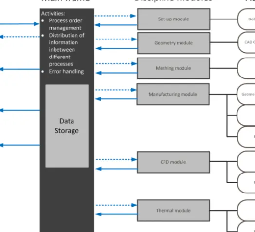
In this paper a tool for assessing manufacturability and sustainability in early stages is presented. It is intended to be a part of a larger system to analyse conceptual designs (see Figure 1). When a parametric CAD-model of a design concept is made, the purpose is to find out how changes of the geometrical and environmental (e.g. temperature) parameters affect the performance of the concept. It is done by creating a
1
Corresponding Author, E-Mail: tim.heikkinen@ju.se
E
Transdisciplinary Engineering: Crossing Boundaries M. Borsato et al. (Eds.)© 2016 The authors and IOS Press.
This article is published online with Open Access by IOS Press and distributed under the terms of the Creative Commons Attribution Non-Commercial License 4.0 (CC BY-NC 4.0). doi:10.3233/978-1-61499-703-0-947
multitude of variants of the CAD-model (in the order of hundreds) and environmental definitions by use of Design of Experiments (DoE). These models are then analysed using FEA and CFD software. Making all these analyses interactively is too time consuming. Instead the process has been automated so that all analyses can be run on a powerful cluster in a matter of hours or days. The results can then be reviewed, making it possible to better understand the possible trade-offs so that insightful design decisions can be taken.
This system has formerly not been capable of analysing manufacturability. As part of the work presented here, a rule-based evaluation of the manufacturability has been added. The method results in list(s) of operations which are evaluated with respect to sustainability, manufacturing preference, and cost. A case of application is presented for evaluation of the tool on the weldability of static turbine parts.
Figure 1. Envisioned future system.
1. Method
The work which this paper is based on originates from a master thesis [1]. In the master thesis the DRM (Design Research Methodology) [2] has been employed. It involved interviewing staff at the aerospace company where the thesis work was conducted to first describe the current state and then finding in which aspects to improve in
consecu-tive descripconsecu-tive and prescripconsecu-tive loops. Five key employees were interviewed in this fashion; domain experts within thermal analysis (developer), parametric CAD devel-opment (developer), design of experiment (user), and computational fluid analysis (developer). Further by daily being present at the company for about six months in the spring of 2015, informal opportunities emerged to learn more about the state of practice at the company.
2. Literature
Within the field of Set-based Concurrent Engineering (SBCE), reuse of knowledge is a cornerstone [3]. Failing to reuse knowledge has also been found to hinder the positive effects of SBCE [4]. One way to represent knowledge is the use of visualization, often referred to as “visual knowledge”. There is no common definition but it is often used to describe a palette of approaches that aims at displaying complex information in an efficient way for product design and project planning [5]. Visual knowledge is also recognized as a tool to capture, communicate and document corporate knowledge [6]. One type of visual knowledge is trade- off curves, usually graphical representations of the relations between different parameters. Carefully made trade-off curves can be generic, which implies that the results can be reused in following projects. Deriving curves from experiments, human knowledge or from response surfaces leads to the build-up of knowledge of a product. It is also a source of verifying that the knowledge base is accurate since these curves can be verified by experiments. Trade-off curves and similar structured codified information obtained through systematic tests and simulations is also important in the Lean Product Development approach [5].
2.1. Manufacturability Assessment Systems
Manufacturability has traditionally been discussed from a machining point of view. Features in CAD models are identified interactively and automatically by feature recognition such that a process plan for their manufacture can be generated [7]. These process plans form the basis for planning toolpaths and making predictions on the manufacturing costs.
However, evaluating manufacturability is not restricted to automated process planning of machining. Using MAS (Manufacturability Analysis System) [8] many other aspects of manufacturability can be analysed. Manufacturability Assessment Systems (MAS) have three main mechanisms; capture, analyse and evaluate
There have been numerous attempts on evaluation of geometries for weld processes to find the cost of welding a particular geometry represented in CAD. Some examples: [9], [10], [11]. These are based on the automated or interactive evaluation of CAD-models. Ordinary CAD models only hold the geometrical information. This type of CAD models can be said to be augmented with various manufacturing information. 2.2. Sustainability
The work presented here will result in process plans for the various manufacturing operations. Having such plans enables the evaluation of sustainability, e.g. as presented in [12]. Many of the products that are designed today can be expected to be manufactured for a long time. One example is aviation, where the airframes are T. Heikkinen et al. / Automated Producibility Assessment Enabling SBCE 949
expected to be in use for decades. Therefore not only environmental sustainability aspects need to be taken into account but also the long-term economic and social sustainability [13].
3. Results
Through structured and informal interviews it was concluded in which aspects the CAE environment needed to improve. The number of "loop-backs" between the design and production needed to be decreased. This was planned to be addressed by introducing the manufacturability module in the CAE environment. The measurable success criteria which will be used as one part to evaluate the level of success are:
x Number of increased manufacturing constraints caught. x Number of increased producibility metrics caught.
The final evaluation of the suggested manufacturing module is made by measuring the identified success criteria variables as well as presenting it to affected employees and listening to their feedback.
3.1. Manufacturing module
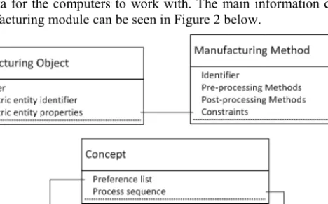
Since the manufacturing module presented here is intended to be a part of a CAE envi-ronment where hundreds of geometric models are analysed automatically the same level of automation is required. As with any automation task this requires well-structured data for the computers to work with. The main information classes utilized by this manufacturing module can be seen in Figure 2 below.
Figure 2. Manufacturing module, information classes and relations.
The five different classes are: manufacturing object, manufacturing method, con-cept, preference list, and process sequence. The Manufacturing Object refers to geo-metric entities which are thought to be manufactured. It contains two identifiers, one to itself and another to the geometric entity, as well as properties of the geometric entity.
Examples of geometric entities are edges, faces, or bodies. Properties could be as sim-ple as weight and dimensions or data used for conducting reachability analyses. Manu-facturing Method represents available operations to realize the manuManu-facturing objects. It can be instantiated to represent e.g. weld or machining processes including its pre and post processes such as washing and deburring. Each process, pre- and post-processes included, are also associated with a number of constraints relating to the manufacturing object properties. There are also the Preference List, which can be used to denote the preference of the different methods in a particular workshop, and the Process Sequence, which describes the sequence of realising the manufacturing objects. These two can of course become extremely complex to define. One way of supporting this has been to enable the instantiation of several so called Concept-classes which can represent variations of the preference lists and process sequences, ultimately visualiz-ing the impacts of altervisualiz-ing them. Figure 3 below is a flow-chart attemptvisualiz-ing to aid in understanding how the information classes are used throughout the manufacturing module.
Figure 3. Manufacturing module, process and information flow
The first two actions are to Get Geometric Entity Data and Get Manufacturing Methods and Constraints which represent the geometric entities and available manufacturing operations along with its constraints, stored as instances of the Manufacturing Object class and Manufacturing Method class respectively. Once the geometric entities and available operations have been retrieved the feasibility of each method is checked on each geometric entity by evaluating if any constraints have been breached. This is the Check Methods feasibility for Objects activity. Each defined configuration of preferred manufacturing methods and process sequences, stored as instances of the Concept class, are then retrieved in the Get Concept activity comprised of Get Object Sequence and Get Object Preference List activities. These are all worked upon by first Choosing Manufacturing Method for each manufacturing object, which is based upon which method of the feasible ones that was highest ranked in the preference list retrieved. Followed by Create List of Operations, where each method is placed in the correct order defined by the object sequence retrieved. Finally, the list of operations is evaluated with respect to manufacturability and sustainability in the Evaluate List of Operations activity.
3.2. Test case related to welding
A test case has been applied to the welding of a static turbine part as depicted in Figure 4 below. There is a sequence for the welding often starting with building sub-assemblies as several sectors. The component consists of several cast or sheet metal parts that are welded together. These type of products have very high demands on quality. Therefore, the parts are to be inspected rigorously to detect any faults, such as cracks. The length of the service interval depends on the length of the largest crack. The parts are checked using both x-ray and dye penetrant investigations.
Figure 4. Static turbine part.
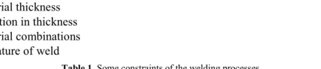
The parts and sub-assemblies are welded together using robotic welding. There are several types of welding methods such as TIG, Laser, Electron beam and Plasma. Each requires several different pre- and post-processing operations and have a number of different constraints related to:
x Access for welding x Access for inspection x Material thickness x Variation in thickness x Material combinations x Curvature of weld
Table 1. Some constraints of the welding processes.
Process Curvature Thickness of plate Material Reachability x, y, z
Laser min R=20 0,25mm - 20mm Fe, Al, Ni, Ti 210, 240, 230 Electron min R=30 0,3mm-50 mm Fe, Al, Ni, Ti ...
TIG min R=15 0,7mm-8mm <List> 300, 70, 70 Plasma min R=35 0,075mm-6mm <List> ...
Table 1 gives some examples, some from GRANTA’s CES EduPack2 software, the actual values used are confidential.
The manufacturing module has been realized in the existing CAE environment by using the MS Excel program to manage the user input and to review the results. For controlling the program flow scripts have been written as Excel macros, Siemens NX journals, and Siemens NX Knowledge Fusion (KF) rules. The declarative scripting language KF has been used for the I/O-interface to the CAD-model. KF has been useful in that the geometric entities and their properties are efficiently transcribed directly to the Excel document. Siemens NX Journals enabled the instantiation and execution of KF rules. Excel macros were used to perform the necessary data analyses.
The KF application works by first retrieving the necessary inputs given by the user in an Excel file. In this case the inputs given were names of the geometric entities to get data from and the names of the corresponding geometric entities which could cause a reachability issue. It knows which cells to read with a user-defined Excel named range. Reachability assessments are then conducted by first projecting lines in the direction of the normal of the corresponding face (see Figure 5). Secondly checking for collision with the user specified constraining entity(s) given. Finally, if the lines do not collide, the maximum allowed angle of the lines to the entity(s) is saved for export. However, if it collided only the distance to the object is withdrawn.
Figure 5. Reachability analysis.
What method that is finally used depends mainly on the conditions at the welding place, the possibility to access with the weld gun, and which type of joint that is re-quired. If there are several feasible methods however the preferences differ depending on whom you ask. To enable the evaluation of different variations relating to the pref-erences as well as process sequences the use of “Concepts” were introduced. In this case two such concepts were defined and the difference is manufacturability could be retrieved for further analysis. Figure 6 below shows a small section of a couple of lists of operations created as a result of different concept-definitions. The first concept
2
http://www.grantadesign.com/education/edupack/
clearly favours the electron beam welding and the second the laser beam welding. Also seen are pre- and post-processing steps such as spot welding for initial alignment, dif-ferent cleaning procedures, and very important inspections.
Figure 6. Results of the analysis.
As a result of supplying a list of operations different estimates could be estab-lished. Manufacturability preference index was one which was calculated as a result of how preferred the different methods chosen were. Cost could be approximated by looking at historical cost-results of the different operations. Sustainability metrics was being developed in a different research project depending on e.g. material choices and chemicals needed in the different processes.
3.3. Evaluation
The measurable success criteria “Number of increased manufacturing constraints caught” was increased by two, one was the maximum curvature of edges and another was related to reachability. “Number of increased producibility metrics caught” was increased by three, which are manufacturing preferred index, cost, and sustainability.
As a result of presenting the method and the prototype system to an audience varying from experts within producibility assessments, design methods, and
simulations the feedback is positive but skeptical. Nobody questions the importance of enabling producibility assessments. However, they wonder about the list of preference and how it could be realized. Others gave examples of what the system did not catch; such as if several fixtures are necessary or how material deformations due to localized heat, such as in welding, is affected.
4. Discussion
A method for assessing manufacturability in early stages of design has been proposed and demonstrated through a case of robotic welding. The method enables an automated assessment of large amounts of concepts, reaching the hundreds. These large number of evaluated concepts provides the capability of providing visual knowledge in the form of trade-offs between the manufacturing discipline and others. It is essentially a MAS method specialised for the early phases of product development and large numbers of concepts providing cost, sustainability, and manufacturing preference metrics. It can provide a repeatable and quick evaluation, which if used routinely in the development process makes it possible to increase the company’s capability in concurrent engineering by involving the production in earlier stages of design. The rapid evaluation of proposed design concepts can enable the company to quickly respond to requests for changes in the requirements and to predict the consequences of requirement changes. The set of different conceptual designs that can be evaluated during the same amount of time is expected to increase the possibility for SBCE. However, when interviewing the staff and incorporating the prototype system into the companies IT-infrastructure some issues emerged. It primarily involved knowledge acquisition and trustworthiness of the different metrics.
Utilising interviews of experts as the main source of acquiring knowledge with re-spect to rules, constraints, and available methods was time-consuming. In order to keep the tool up to date this has to be repeated regularly. Rules and constraints are expected to change over time as the production methods are continuously developed. The tool needs to be updated to supply relevant results. One interesting way of assisting maintenance as well as search of constraints could be to utilise different data-analysis approaches such as machine learning. The interviews have indicated that process “win-dows” exist. These windows are favourable combinations of processing parameters that can be found for certain combinations of materials and weld-methods. However, they cannot be caught and expressed as simple rules in an interview context.
The other issue involves the trustworthiness or accuracy of the metrics. In the pro-posed prototype system the manufacturing preference index, cost, and sustainability are used to rank the design suggestions. All analyses, in the entire CAE system, are simplified to increase analysis speed and because the information required for detailed analysis is missing in these early stages of development. However, all other modules work with well-established physical laws where the loss of accuracy is known to some extent. The manufacturing cost can change unexpectedly due to malfunctioning machines and materials cost fluctuations etc. Sustainability all the same with new discoveries regarding which materials and chemicals that affect the environment or have negative social and economic effects. Not to mention new technological solutions emerging and taking over. What basis the manufacturing preference index is based upon has not been addressed in this paper and it is partially due to its poor established definition. It might have been a product of the complexity involved. Cost and
sustainability evaluations were not possible to model to a satisfactory level of accuracy at the time. The number of factors affecting these metrics were overwhelming. Being able to formalise rules which take current and future manufacturing potential as well as sustainability aspects into consideration is a tall, if not impossible, order. The manufacturing preferred index therefore enables the user to affect the weight of each method based on his intuition or tacit knowledge. It is a metric which is thought to disappear as the knowledge regarding cost and sustainability analyses is improved.
5. Conclusion
Manufacturability analysis in the early design stages is a way to increase the capability for companies to respond to requirement changes from their customers and to improve their prospects for SBCE. A method has been introduced and evaluated which extends the technology platform with rule and constraint based manufacturability evaluation. Gathering the information needed and keeping it up-to-date as well as calculating and interpreting the results has shown to be obstacles when attempting to put the method into service. Using rough cost and sustainability estimates as the only means of ranking the design suggestions is not sufficient. Streaming data from production and utilizing machine learning as a means of producing up-to-date relevant rules has been presented as one aim for future work.
References
[1] T. Heikkinen and J. Müller, Multidisciplinary analysis of jet engine components: Development of
methods and tools for design automatisation in a multidisciplinary context, Jönköping University,
http://urn.kb.se/resolve?urn=urn:nbn:se:hj:diva-27784, 2015.
[2] L. T. M. Blessing, DRM, a design research methodology, Springer, London, 2009.
[3] D. K. Sobek II, A. C. Ward, and J. K. Liker, Toyota's principles of set-based concurrent engineering,
Sloan Management Review, vol. 40, pp. 67-83, Winter99 1999.
[4] D. Raudberget, Practical applications of set-based concurrent engineering in industry, Strojniski
Vestnik/Journal of Mechanical Engineering, Vol. 56, 2010, pp. 685-695.
[5] M. Kennedy, Ready, set, dominate : implement Toyota's set-based learning for developing products and
nobody can catch you, Oaklea Press, Richmond, 2008.
[6] A. C. Ward, Lean product and process development, Lean Enterprise Institute, Cambridge, 2007. [7] J. J. Shah, Parametric and feature-based CAD/CAM : concepts, techniques, and applications, Wiley,
New York, 1995.
[8] S. A. Shukor and D. A. Axinte, Manufacturability analysis system: Issues and future trends, International
Journal of Production Research, Vol. 47, 2009, pp. 1369-1390.
[9] P. G. Maropoulos, Z. Yao, H. D. Bradley and K. Y. G. Paramor, An integrated design and planning environment for welding: Part 1: Product modelling, Journal of Materials Processing Technology, Vol. 107, 2000, pp. 3-8.
[10] S. Chayoukhi, Z. Bouaziz and A. Zghal, Cost estimation of joints preparation for GMAW welding process using feature model, Journal of Materials Processing Technology, vol. 199, 2008, pp. 402-411. [11] F. Elgh and M. Cederfeldt, Cost-based producibility assessment: analysis and synthesis approaches
through design automation, Journal of Engineering Design, Vol. 19, 2008, pp. 113-130.
[12] S. I. Hallstedt, M. Bertoni and O. Isaksson, Assessing sustainability and value of manufacturing processes: a case in the aerospace industry, Journal of Cleaner Production, Vol. 108, Part A, 2015, pp. 169-182.
[13] S. I. Hallstedt, A. W. Thompson and P. Lindahl, Key elements for implementing a strategic sustainability perspective in the product innovation process, Journal of Cleaner Production, Vol. 51, 2013, pp. 277-288.