O N IT O R IN G O F A U TO M A TE D D R IV IN G S YS TE M S 20 19 ISBN 978-91-7485-434-3 ISSN 1651-9256
Address: P.O. Box 883, SE-721 23 Västerås. Sweden Address: P.O. Box 325, SE-631 05 Eskilstuna. Sweden E-mail: info@mdh.se Web: www.mdh.se
RUNTIME MONITORING OF AUTOMATED DRIVING SYSTEMS
Ayhan Mehmed
2019
School of Innovation, Design and Engineering
RUNTIME MONITORING OF AUTOMATED DRIVING SYSTEMS
Ayhan Mehmed
2019
Copyright © Ayhan Mehmed, 2019 ISBN 978-91-7485-434-3
ISSN 1651-9256
Printed by E-Print AB, Stockholm, Sweden
Copyright © Ayhan Mehmed, 2019 ISBN 978-91-7485-434-3
ISSN 1651-9256
Abstract
Vehicles with automated driving capabilities target making driving safer, more comfortable, and economically more efficient by assisting the driver or by tak-ing responsibilities for different drivtak-ing tasks. While vehicles with assistance and partial automation capabilities are already in series production, the ultimate goal is in the introduction of vehicles with full automated driving capabilities. Reaching this level of automation will require shifting all responsibilities, in-cluding the responsibility for the overall vehicle safety, from the human to the computer-based system responsible for the automated driving functional-ity (i.e., the Automated Driving System (ADS)). Such a shift makes the ADS highly safety-critical, requiring a safety level comparable to an aircraft system. It is paramount to understand that ensuring such a level of safety is a complex interdisciplinary challenge. Traditional approaches for ensuring safety have worked well for ensuring the safety of standard, well constraint, and deterministic automotive control systems (e.g., anti-lock braking system). However, these approaches are unproven, given the novelty and complexity of the technology in ADSs, and currently, there is no single straightforward solution for ensuring the automated vehicle’s safety. Instead, the consensus of cross-domain experts is to use a set of complementary safety methods that combined are sufficient to ensure the required level of safety.
In the context of automated driving, runtime monitors that verify the safe operation during its execution, are a promising complementary approach for ensuring safety. However, to develop a runtime monitoring solution for ADS, one has to handle a wide range of challenges. On a conceptual level, the com-plex and opaque technology used in ADS often make researchers ask the ques-tion “how should ADS be verified in order to judge it is operating safely?”.
i
Abstract
Vehicles with automated driving capabilities target making driving safer, more comfortable, and economically more efficient by assisting the driver or by tak-ing responsibilities for different drivtak-ing tasks. While vehicles with assistance and partial automation capabilities are already in series production, the ultimate goal is in the introduction of vehicles with full automated driving capabilities. Reaching this level of automation will require shifting all responsibilities, in-cluding the responsibility for the overall vehicle safety, from the human to the computer-based system responsible for the automated driving functional-ity (i.e., the Automated Driving System (ADS)). Such a shift makes the ADS highly safety-critical, requiring a safety level comparable to an aircraft system. It is paramount to understand that ensuring such a level of safety is a complex interdisciplinary challenge. Traditional approaches for ensuring safety have worked well for ensuring the safety of standard, well constraint, and deterministic automotive control systems (e.g., anti-lock braking system). However, these approaches are unproven, given the novelty and complexity of the technology in ADSs, and currently, there is no single straightforward solution for ensuring the automated vehicle’s safety. Instead, the consensus of cross-domain experts is to use a set of complementary safety methods that combined are sufficient to ensure the required level of safety.
In the context of automated driving, runtime monitors that verify the safe operation during its execution, are a promising complementary approach for ensuring safety. However, to develop a runtime monitoring solution for ADS, one has to handle a wide range of challenges. On a conceptual level, the com-plex and opaque technology used in ADS often make researchers ask the ques-tion “how should ADS be verified in order to judge it is operating safely?”.
ii
Once the initial Runtime Verification (RV) concept is developed, re-searchers and practitioners have to deal with research and engineering chal-lenges encountered during the realization of the RV approaches into an actual runtime monitoring solution for ADS. These challenges range from, estimating different safety parameters of the runtime monitors, finding solutions for dif-ferent technical problems, to meeting scalability and efficiency requirements.
This thesis is proposing novel runtime monitoring solutions for verifying the safe operation of ADS. This encompasses (i) defining novel RV approaches explicitly tailored for automated driving, and (ii) developing concepts, meth-ods, and architectures for realizing the RV approaches into an actual runtime monitoring solution for ADS. Contributions to the former include defining two runtime verification approaches, namely the Computer Vision Monitor (CVM) and the Safe Driving Envelope Verification. The latter includes (i) estimating the sufficient diagnostic test interval of the runtime verification approaches (in particular the CVM), (ii) addressing the out-of-sequence measurement prob-lem in sensor fusion-based ADS, and (iii) developing an architectural solution for improving the scalability and efficiency of the runtime monitoring solution.
Sammanfattning
Fordon med automatiserad k¨orf¨orm˚aga f¨orv¨antas k¨ora s¨akrare, bekv¨amare och ekonomiskt effektivare genom att hj¨alpa f¨oraren och genom att ta ansvar f¨or olika k¨oruppgifter. Aven om fordon med vissa k¨orfunktioner automa-¨ tiserade redan ¨ar i serieproduktion, ¨ar det ultimata m˚alet fordon som kan k¨ora helt p˚a egen hand. F¨or att n˚a denna automatiseringsniv˚a kr¨avs att alla ansvarsomr˚aden, inklusive ansvaret f¨or den totala fordonss¨akerheten, ¨overf¨ors fr˚an det m¨anskliga till det datorbaserade systemet (dvs. det automatiska k¨orsystemet (the Automated Driving System; ADS)). En s˚adan f¨orskjutning av ansvar kr¨aver en s¨akerhetsniv˚a som ¨ar j¨amf¨orbar med den som g¨aller f¨or flygplan.
Att n˚a en s˚adan s¨akerhetsniv˚a utg¨or en komplex tv¨arvetenskaplig utman-ing. Traditionella metoder f¨or att s¨akerst¨alla systemets funktionss¨akerhet kr¨aver anv¨andning av feltoleranstekniker som inte ¨ar bepr¨ovade n¨ar det g¨aller sj¨alvk¨orande fordon. Dessutom lider befintliga s¨akerhetsmetoder (t.ex. ISO 26262) av krav som ¨ar ofullst¨andiga i det automatiska k¨orsammanhanget. F¨or n¨arvarande finns det ingen uppenbar enkel l¨osning f¨or dessa utmaningar. Den allm¨anna uppfattningen hos experter i omr˚adet ¨ar att det kommer att kr¨avas en upps¨attning kompletterande s¨akerhetsmetoder som tillsammans ¨ar tillr¨ackliga f¨or att s¨akerst¨alla den n¨odv¨andiga s¨akerhetsniv˚an.
Runtimemonitorer som verifierar ADSers s¨akerhet under drift ¨ar en lo-vande kompletterande strategi f¨or att h¨oja s¨akerhetsniv˚an. En s˚adan l¨osning kr¨aver dock att ett brett spektrum av utmaningar adresseras. En ¨overgripande fr˚aga ¨ar “hur ska ADS verifieras f¨or att man ska kunna avg¨ora att det fungerar s¨akert?”.
iii
Sammanfattning
Fordon med automatiserad k¨orf¨orm˚aga f¨orv¨antas k¨ora s¨akrare, bekv¨amare och ekonomiskt effektivare genom att hj¨alpa f¨oraren och genom att ta ansvar f¨or olika k¨oruppgifter. Aven om fordon med vissa k¨orfunktioner automa-¨ tiserade redan ¨ar i serieproduktion, ¨ar det ultimata m˚alet fordon som kan k¨ora helt p˚a egen hand. F¨or att n˚a denna automatiseringsniv˚a kr¨avs att alla ansvarsomr˚aden, inklusive ansvaret f¨or den totala fordonss¨akerheten, ¨overf¨ors fr˚an det m¨anskliga till det datorbaserade systemet (dvs. det automatiska k¨orsystemet (the Automated Driving System; ADS)). En s˚adan f¨orskjutning av ansvar kr¨aver en s¨akerhetsniv˚a som ¨ar j¨amf¨orbar med den som g¨aller f¨or flygplan.
Att n˚a en s˚adan s¨akerhetsniv˚a utg¨or en komplex tv¨arvetenskaplig utman-ing. Traditionella metoder f¨or att s¨akerst¨alla systemets funktionss¨akerhet kr¨aver anv¨andning av feltoleranstekniker som inte ¨ar bepr¨ovade n¨ar det g¨aller sj¨alvk¨orande fordon. Dessutom lider befintliga s¨akerhetsmetoder (t.ex. ISO 26262) av krav som ¨ar ofullst¨andiga i det automatiska k¨orsammanhanget. F¨or n¨arvarande finns det ingen uppenbar enkel l¨osning f¨or dessa utmaningar. Den allm¨anna uppfattningen hos experter i omr˚adet ¨ar att det kommer att kr¨avas en upps¨attning kompletterande s¨akerhetsmetoder som tillsammans ¨ar tillr¨ackliga f¨or att s¨akerst¨alla den n¨odv¨andiga s¨akerhetsniv˚an.
Runtimemonitorer som verifierar ADSers s¨akerhet under drift ¨ar en lo-vande kompletterande strategi f¨or att h¨oja s¨akerhetsniv˚an. En s˚adan l¨osning kr¨aver dock att ett brett spektrum av utmaningar adresseras. En ¨overgripande fr˚aga ¨ar “hur ska ADS verifieras f¨or att man ska kunna avg¨ora att det fungerar s¨akert?”.
iv
N¨ar en konceptuell l¨osning f¨or Runtime Verifiering (RV) under drift utvecklats, ˚aterst˚ar utmaningen att implementera en l¨osning som fungerar i praktiken. Centrala delproblem ¨ar h¨ar att hitta s¨att att uppskatta relevanta s¨akerhetsparametrar f¨or runtimemonitoreringen, l¨osa diverse tekniska problem, samt att skalbarhets- och effektivitetskrav.
I denna avhandling f¨oresl˚ar vi nya ¨overvakningsl¨osningar f¨or att un-der drift verifiera ADSers s¨akerhet. Detta omfattar (i) att definiera nya metoder f¨or verifiering under drift, specifikt skr¨addarsydda f¨or automatiserad k¨orning, och (ii) utveckla koncept, metoder och arkitekturer f¨or att realis-era RV-tillv¨agag˚angss¨atten i praktiskt fungrealis-erande k¨ortid¨overvakningsl¨osning f¨or ADS. Bidrag till (i) inkluderar tv˚a RV-tillv¨agag˚angss¨att, n¨amligen Com-puter Vision Monitor (CVM) och Verifiering av s¨akra k¨orintervaller. Bidrag till (ii) inkluderar (a) uppskattning av tillr¨ackligt diagnostiskt testinter-vall f¨or k¨ortidsverifieringsmetoderna (i synnerhet CVM), (b) adressering av m¨atproblemet utanf¨or sekvensen i sensorfusionsbaserade ADSer, och (c) utveckling en arkitektonisk l¨osning som f¨orb¨attrar skalbarhet och effektivitet vid ¨overvakning under drift.
List of publications
Publications Included in the Thesis
1Paper A Improving Dependability of Vision-Based Advanced Driver Assis-tance Systems Using Navigation Data and Checkpoint Recognition, Ayhan Mehmed, Sasikumar Punnekkat, Wilfried Steiner, Giacomo Spampinato, and Martin Lettner. In International Conference on Com-puter Safety, Reliability, and Security (SafeComp) Delft, The Nether-lands, September 2015. Springer, LNCS.
Paper B Improving Intelligent Vehicle Dependability By Means of Infrastructure-Induced Tests, Wilfried Steiner, Ayhan Mehmed, Sasikumar Punnekkat. In International Workshop on Safety and Secu-rity of Intelligent Vehicles (SSIV), DSN, Rio de Janeiro, Brazil, June 2015. IEEE Computer Society.
Paper C Deterministic Ethernet: Addressing the Challenges of Asynchronous Sensing in Sensor Fusion Systems, Ayhan Mehmed, Sasikumar Pun-nekkat, Wilfried Steiner. In International Workshop on Safety and Secu-rity of Intelligent Vehicles (SSIV), DSN, Denver, CO, USA, June 2017. IEEE Computer Society.
Paper D System Architecture and Application-Specific Verification Method for Fault-Tolerant Automated Driving System, Ayhan Mehmed, Wilfried Steiner, Moritz Antlanger, Sasikumar Punnekkat. In Workshop on En-suring and Validating Safety for Automated Vehicles (EVSAV), IV Sym-posium, Paris, France, June 2019. IEEE Computer Society.
1The included publications are reformatted to comply with the thesis printing format.
vii
List of publications
Publications Included in the Thesis
1Paper A Improving Dependability of Vision-Based Advanced Driver Assis-tance Systems Using Navigation Data and Checkpoint Recognition, Ayhan Mehmed, Sasikumar Punnekkat, Wilfried Steiner, Giacomo Spampinato, and Martin Lettner. In International Conference on Com-puter Safety, Reliability, and Security (SafeComp) Delft, The Nether-lands, September 2015. Springer, LNCS.
Paper B Improving Intelligent Vehicle Dependability By Means of Infrastructure-Induced Tests, Wilfried Steiner, Ayhan Mehmed, Sasikumar Punnekkat. In International Workshop on Safety and Secu-rity of Intelligent Vehicles (SSIV), DSN, Rio de Janeiro, Brazil, June 2015. IEEE Computer Society.
Paper C Deterministic Ethernet: Addressing the Challenges of Asynchronous Sensing in Sensor Fusion Systems, Ayhan Mehmed, Sasikumar Pun-nekkat, Wilfried Steiner. In International Workshop on Safety and Secu-rity of Intelligent Vehicles (SSIV), DSN, Denver, CO, USA, June 2017. IEEE Computer Society.
Paper D System Architecture and Application-Specific Verification Method for Fault-Tolerant Automated Driving System, Ayhan Mehmed, Wilfried Steiner, Moritz Antlanger, Sasikumar Punnekkat. In Workshop on En-suring and Validating Safety for Automated Vehicles (EVSAV), IV Sym-posium, Paris, France, June 2019. IEEE Computer Society.
1The included publications are reformatted to comply with the thesis printing format.
viii
Additional Publications not Included in the Thesis
21. Development of Sensor Fusion Based ADAS Modules in Virtual Envi-ronments, Velibor Ili´c, Maliˇsa Marijan, Ayhan Mehmed, and Moritz Antlanger, Zooming Innovation in Consumer Technologies Conference (ZINC), Novi Sad, Serbia , May 2018. IEEE Computer Society. 2. Next generation real-time networks based on IT technologies, Wilfried
Steiner, Pablo Guti´errez Pe´on, Marina Guti´errez, Ayhan Mehmed, Guillermo Rodriguez-Navas, Elena Lisova, Francisco Pozo, Interna-tional Conference on Emerging Technologies and Factory Automation (ETFA), Berlin, Germany , September 2016. IEEE Computer Society.
2The publications are listed in reverse chronological order.
viii
Additional Publications not Included in the Thesis
21. Development of Sensor Fusion Based ADAS Modules in Virtual Envi-ronments, Velibor Ili´c, Maliˇsa Marijan, Ayhan Mehmed, and Moritz Antlanger, Zooming Innovation in Consumer Technologies Conference (ZINC), Novi Sad, Serbia , May 2018. IEEE Computer Society. 2. Next generation real-time networks based on IT technologies, Wilfried
Steiner, Pablo Guti´errez Pe´on, Marina Guti´errez, Ayhan Mehmed, Guillermo Rodriguez-Navas, Elena Lisova, Francisco Pozo, Interna-tional Conference on Emerging Technologies and Factory Automation (ETFA), Berlin, Germany , September 2016. IEEE Computer Society.
Contents
I
Thesis
1
1 Introduction 3
1.1 Problem Statement . . . 6
1.2 Scope of the Thesis . . . 11
1.3 Thesis Outline . . . 11
2 Research Summary 13 2.1 Research Methodology . . . 13
2.2 Research Problems . . . 17
2.2.1 RP A: The Verification Approach . . . 18
2.2.2 RP B: Defining the Diagnostic Test Interval . . . 18
2.2.3 RP C: The Out-of-Sequence Measurements Problem . 19 2.2.4 RP D: Scalability . . . 20
2.2.5 RP E: Efficiency . . . 20
2.3 Research Goals . . . 21
3 Thesis Contributions and Overview of Included Papers 23 3.1 Thesis Contributions . . . 24
3.1.1 C1: The Computer Vision Monitor Concept . . . 25
3.1.2 C2: Estimating the Diagnostic Test Interval . . . 26
3.1.3 C3: Ensuring Precise Sensor Measurements Times-tamping . . . 26
3.1.4 C4: The Safe Driving Envelope Verification Concept . 27 3.1.5 C5: The Verification Modules . . . 29
3.1.6 C6: Efficiency Improvements . . . 30 ix
Contents
I
Thesis
1
1 Introduction 3 1.1 Problem Statement . . . 61.2 Scope of the Thesis . . . 11
1.3 Thesis Outline . . . 11
2 Research Summary 13 2.1 Research Methodology . . . 13
2.2 Research Problems . . . 17
2.2.1 RP A: The Verification Approach . . . 18
2.2.2 RP B: Defining the Diagnostic Test Interval . . . 18
2.2.3 RP C: The Out-of-Sequence Measurements Problem . 19 2.2.4 RP D: Scalability . . . 20
2.2.5 RP E: Efficiency . . . 20
2.3 Research Goals . . . 21
3 Thesis Contributions and Overview of Included Papers 23 3.1 Thesis Contributions . . . 24
3.1.1 C1: The Computer Vision Monitor Concept . . . 25
3.1.2 C2: Estimating the Diagnostic Test Interval . . . 26
3.1.3 C3: Ensuring Precise Sensor Measurements Times-tamping . . . 26
3.1.4 C4: The Safe Driving Envelope Verification Concept . 27 3.1.5 C5: The Verification Modules . . . 29
3.1.6 C6: Efficiency Improvements . . . 30
x Contents
3.2 Overview of Included Papers . . . 30
3.2.1 Paper A: Improving Dependability of Vision-Based Advanced Driver Assistance Systems Using Naviga-tion Data and Checkpoint RecogniNaviga-tion . . . 30
3.2.2 Paper B: Improving Intelligent Vehicle Dependability By Means of Infrastructure-Induced Tests . . . 31
3.2.3 Paper C: Deterministic Ethernet: Addressing the Chal-lenges of Asynchronous Sensing in Sensor Fusion Sys-tems . . . 31
3.2.4 Paper D: System Architecture and Application-Specific Verification Method for Fault-Tolerant Auto-mated Driving System . . . 32
4 Related Work 35 4.1 Academic Survey . . . 35
4.2 Industrial Survey . . . 36
5 Conclusions and Future Work 39 5.1 Conclusions . . . 39
5.2 Future Work . . . 40
Bibliography 41
II
Included Papers
45
6 Paper A: Improving Dependability of Vision-Based Advanced Driver Assis-tance Systems Using Navigation Data and Checkpoint Recognition 47 6.1 Introduction . . . 496.2 Problem Statement . . . 51
6.3 The Computer-Vision Monitor (CVM) Concept . . . 52
6.4 Reliability Analysis . . . 54
6.4.1 Functional Hazard Analysis . . . 54
6.4.2 FTA for Vision-Based ADAS . . . 55
6.4.3 FTA for Vision-Based ADAS with CVM . . . 57
6.5 Conclusions and Future Work . . . 63
Bibliography . . . 64
x Contents 3.2 Overview of Included Papers . . . 30
3.2.1 Paper A: Improving Dependability of Vision-Based Advanced Driver Assistance Systems Using Naviga-tion Data and Checkpoint RecogniNaviga-tion . . . 30
3.2.2 Paper B: Improving Intelligent Vehicle Dependability By Means of Infrastructure-Induced Tests . . . 31
3.2.3 Paper C: Deterministic Ethernet: Addressing the Chal-lenges of Asynchronous Sensing in Sensor Fusion Sys-tems . . . 31
3.2.4 Paper D: System Architecture and Application-Specific Verification Method for Fault-Tolerant Auto-mated Driving System . . . 32
4 Related Work 35 4.1 Academic Survey . . . 35
4.2 Industrial Survey . . . 36
5 Conclusions and Future Work 39 5.1 Conclusions . . . 39
5.2 Future Work . . . 40
Bibliography 41
II
Included Papers
45
6 Paper A: Improving Dependability of Vision-Based Advanced Driver Assis-tance Systems Using Navigation Data and Checkpoint Recognition 47 6.1 Introduction . . . 496.2 Problem Statement . . . 51
6.3 The Computer-Vision Monitor (CVM) Concept . . . 52
6.4 Reliability Analysis . . . 54
6.4.1 Functional Hazard Analysis . . . 54
6.4.2 FTA for Vision-Based ADAS . . . 55
6.4.3 FTA for Vision-Based ADAS with CVM . . . 57
6.5 Conclusions and Future Work . . . 63
Contents xi
7 Paper B:
Improving Intelligent Vehicle Dependability By Means of Infrastructure-Induced Tests 69
7.1 Introduction . . . 70
7.2 The Computer-Vision Monitor Example . . . 71
7.2.1 Principle of CVM Operation . . . 71
7.2.2 Landmark Maintenance Center . . . 74
7.2.3 Landmark Gathering . . . 75
7.3 CPS Architecture Supporting Infrastructure-Induced Tests . . 76
7.4 Potential Test Scenarios . . . 80
7.4.1 Landmark Occurrence: at Specific Points of Interest . 80 7.4.2 Landmark Occurrence: about Once per Hour . . . 81
7.4.3 Landmark Occurrence: about Once per Minute . . . . 81
7.4.4 Landmark Occurrence: about Once per Second . . . . 81
7.5 Research Directions . . . 82
7.6 Conclusion . . . 83
Bibliography . . . 84
8 Paper C: Deterministic Ethernet: Addressing the Challenges of Asyn-chronous Sensing in Sensor Fusion Systems 87 8.1 Introduction . . . 88
8.2 The OOSM Problem . . . 89
8.2.1 The Kalman Filter . . . 89
8.2.2 The Cause of the OOSM . . . 91
8.2.3 The Effect of OOSM . . . 92
8.2.4 Solutions Dealing with OOSM and their Drawbacks . 93 8.3 Methods for Measurement Timestamping . . . 94
8.3.1 Timestamping Data at Arrival (Centralized Method) . 94 8.3.2 Triggering Method . . . 96
8.3.3 Timestamping at the Time of Acquisition (Distributed Method) . . . 97
8.4 The use of Deterministic Ethernet Networks for Precise Times-tamping . . . 98
8.4.1 System-wide Synchronized Time . . . 99
8.4.2 Low Latency and Jitter . . . 99
8.4.3 Suitability of the Standards for Achieving Precise Measurement Timestamps . . . 100
8.5 Conclusion and Future Work . . . 103
Contents xi 7 Paper B: Improving Intelligent Vehicle Dependability By Means of Infrastructure-Induced Tests 69 7.1 Introduction . . . 70
7.2 The Computer-Vision Monitor Example . . . 71
7.2.1 Principle of CVM Operation . . . 71
7.2.2 Landmark Maintenance Center . . . 74
7.2.3 Landmark Gathering . . . 75
7.3 CPS Architecture Supporting Infrastructure-Induced Tests . . 76
7.4 Potential Test Scenarios . . . 80
7.4.1 Landmark Occurrence: at Specific Points of Interest . 80 7.4.2 Landmark Occurrence: about Once per Hour . . . 81
7.4.3 Landmark Occurrence: about Once per Minute . . . . 81
7.4.4 Landmark Occurrence: about Once per Second . . . . 81
7.5 Research Directions . . . 82
7.6 Conclusion . . . 83
Bibliography . . . 84
8 Paper C: Deterministic Ethernet: Addressing the Challenges of Asyn-chronous Sensing in Sensor Fusion Systems 87 8.1 Introduction . . . 88
8.2 The OOSM Problem . . . 89
8.2.1 The Kalman Filter . . . 89
8.2.2 The Cause of the OOSM . . . 91
8.2.3 The Effect of OOSM . . . 92
8.2.4 Solutions Dealing with OOSM and their Drawbacks . 93 8.3 Methods for Measurement Timestamping . . . 94
8.3.1 Timestamping Data at Arrival (Centralized Method) . 94 8.3.2 Triggering Method . . . 96
8.3.3 Timestamping at the Time of Acquisition (Distributed Method) . . . 97
8.4 The use of Deterministic Ethernet Networks for Precise Times-tamping . . . 98
8.4.1 System-wide Synchronized Time . . . 99
8.4.2 Low Latency and Jitter . . . 99
8.4.3 Suitability of the Standards for Achieving Precise Measurement Timestamps . . . 100
xii Contents
Bibliography . . . 104
9 Paper D: System Architecture and Application-Specific Verification Method for Fault-Tolerant Automated Driving System 109 9.1 Introduction . . . 110
9.2 Problem Statement and Proposed Solution . . . 111
9.2.1 Unconditional Prioritization . . . 112
9.2.2 The Problem of Replica Determinism . . . 113
9.2.3 Proposed System Architecture . . . 114
9.3 Safety Co-pilot . . . 115
9.3.1 Sensor Fusion . . . 116
9.3.2 Verification Modules . . . 117
9.3.3 Decision Maker . . . 119
9.4 Vehicle Collision Verification . . . 119
9.4.1 Safe Driving Envelope Assembler . . . 120
9.4.2 Safe Driving Envelope Verifier . . . 121
9.5 Experimental Results . . . 121 9.6 Conclusions . . . 124 Bibliography . . . 124 xii Contents Bibliography . . . 104 9 Paper D: System Architecture and Application-Specific Verification Method for Fault-Tolerant Automated Driving System 109 9.1 Introduction . . . 110
9.2 Problem Statement and Proposed Solution . . . 111
9.2.1 Unconditional Prioritization . . . 112
9.2.2 The Problem of Replica Determinism . . . 113
9.2.3 Proposed System Architecture . . . 114
9.3 Safety Co-pilot . . . 115
9.3.1 Sensor Fusion . . . 116
9.3.2 Verification Modules . . . 117
9.3.3 Decision Maker . . . 119
9.4 Vehicle Collision Verification . . . 119
9.4.1 Safe Driving Envelope Assembler . . . 120
9.4.2 Safe Driving Envelope Verifier . . . 121
9.5 Experimental Results . . . 121
9.6 Conclusions . . . 124
I
Thesis
1I
Thesis
1Chapter 1
Introduction
Aiming at better comfort, efficiency, and safer driving experience, Automated Driving(AD) is one of the fastest-growing sectors in the automotive industry. Generally speaking, the AD functionality is implemented in a computer-based system (i.e., the Automated Driving System (ADS)) that perceives the envi-ronment via sensors, calculates driving commands using complex algorithms, and controls the vehicle through actuators. The ADS can support the driving function at different levels of automation (see Figure 1.1).
Figure 1.1: Summary of levels of driving automation. Based on [1].
3
Chapter 1
Introduction
Aiming at better comfort, efficiency, and safer driving experience, Automated Driving(AD) is one of the fastest-growing sectors in the automotive industry. Generally speaking, the AD functionality is implemented in a computer-based system (i.e., the Automated Driving System (ADS)) that perceives the envi-ronment via sensors, calculates driving commands using complex algorithms, and controls the vehicle through actuators. The ADS can support the driving function at different levels of automation (see Figure 1.1).
Figure 1.1: Summary of levels of driving automation. Based on [1].
4 Chapter 1. Introduction
At the lowest level of automation (Level 1 (L1)), the ADS provides assis-tance features like Adaptive Cruise Control (ACC) or Lane Keep Assisassis-tance (LKA). At the intermediate level of automation (L2, L3), the ADS is capable of providing both, ACC and LKA at the same time, as well as other functions like lane change and merge. Passenger vehicles with these levels of AD capa-bilities are already in series production. About 9 million vehicles with L1 and L2 AD capabilities have been sold in 2018 [2]. The first L3 series production vehicle was announced in early 2018 [3].
It is essential to understand that L1-L3 AD capable vehicles, do still require a human driver to be alert and ready to interfere with the ADS’s decisions immediately (L1, L2) or within a predefined time frame (L3). In this case, the ADS can be characterized as in Figure 1.2. Here, the human driver is an operatorthat activates or deactivates the system. Once the activation criteria is met (e.g., the vehicle is in the correct operational design domain), the ADS starts perceiving the environment and the state of the vehicle using a set of sensors(e.g., camera, lidar, radar, inertial measurement unit, etc.).
Figure 1.2: ADS with a human in charge of the backup driving function.
4 Chapter 1. Introduction
At the lowest level of automation (Level 1 (L1)), the ADS provides assis-tance features like Adaptive Cruise Control (ACC) or Lane Keep Assisassis-tance (LKA). At the intermediate level of automation (L2, L3), the ADS is capable of providing both, ACC and LKA at the same time, as well as other functions like lane change and merge. Passenger vehicles with these levels of AD capa-bilities are already in series production. About 9 million vehicles with L1 and L2 AD capabilities have been sold in 2018 [2]. The first L3 series production vehicle was announced in early 2018 [3].
It is essential to understand that L1-L3 AD capable vehicles, do still require a human driver to be alert and ready to interfere with the ADS’s decisions immediately (L1, L2) or within a predefined time frame (L3). In this case, the ADS can be characterized as in Figure 1.2. Here, the human driver is an operatorthat activates or deactivates the system. Once the activation criteria is met (e.g., the vehicle is in the correct operational design domain), the ADS starts perceiving the environment and the state of the vehicle using a set of sensors(e.g., camera, lidar, radar, inertial measurement unit, etc.).
5
Based on the sensor inputs, the Automated Driving Function (ADF) calcu-lates driving commands that it proposes to be executed by the vehicle.
The human driver is also responsible for the backup driving function. Thus, in parallel to the ADS, the human driver perceives the environment and the state of the vehicle (e.g., speed, position, orientation, etc.) in the given context, using human senses. The human driver is ready to interfere with the ADS at any time, e.g., whenever he/she identifies the vehicle operation to be erroneous or receives a request for intervention from the ADS. The prioritization function is designed in a way that the driving commands exercised by the human driver are always and unconditionally prioritized over the driving commands from the ADF. In such a setup, the human driver is responsible for overall vehicle safety, thus, significantly reducing safety requirements towards the ADS.
Ultimately, in the race for higher levels of AD capabilities (L4, L5 in Figure 1.1), all driving responsibilities will be shifted to the ADS, and the driver will no longer be responsible for the backup driving function. Such ADSs have characteristics as depicted in Figure 1.3.
Figure 1.3: ADS without a human in charge of the backup driving function.
5
Based on the sensor inputs, the Automated Driving Function (ADF) calcu-lates driving commands that it proposes to be executed by the vehicle.
The human driver is also responsible for the backup driving function. Thus, in parallel to the ADS, the human driver perceives the environment and the state of the vehicle (e.g., speed, position, orientation, etc.) in the given context, using human senses. The human driver is ready to interfere with the ADS at any time, e.g., whenever he/she identifies the vehicle operation to be erroneous or receives a request for intervention from the ADS. The prioritization function is designed in a way that the driving commands exercised by the human driver are always and unconditionally prioritized over the driving commands from the ADF. In such a setup, the human driver is responsible for overall vehicle safety, thus, significantly reducing safety requirements towards the ADS.
Ultimately, in the race for higher levels of AD capabilities (L4, L5 in Figure 1.1), all driving responsibilities will be shifted to the ADS, and the driver will no longer be responsible for the backup driving function. Such ADSs have characteristics as depicted in Figure 1.3.
6 Chapter 1. Introduction
In this case, the ADS is responsible for performing (i) the ADF, now called Primary ADF, (ii) the backup driving function, also known as Backup ADF, and (iii) the prioritization function. In this setup, the overall responsibility for the automated vehicle safety is within the ADS. The shift of responsibility significantly increases the safety requirements towards the ADS, requiring a safety level comparable to an aircraft system (e.g., about 1 billion operating hours per catastrophic event [4]).
Reaching this level of safety is a complex task that requires numerous cross-domain challenges to be addressed. For example, traditional approaches for ensuring safety require (i) diverse implementation of the ADS components and (ii) the use of fault-tolerance techniques, which however are relatively un-proven, particularly when it comes to the AD domain. We elaborate on these problems in the next section.
1.1
Problem Statement
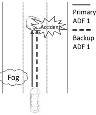
In contrast to a human backup driver, a Backup ADF shall not be prioritized unconditionallyas it can also be in an unsafe state, due to common cause fail-ure. That is, both Primary and Backup ADF may be in failure due to a single internal or external root cause and generate driving commands leading to an accident. Figure 1.4, illustrates an example common cause failure, where due to foggy weather, both Primary and Backup ADF do not recognize a static object (e.g., a rock) on the road, which then leads to a generation of driving commands (e.g., a trajectory) colliding into the object.
Backup ADF 1 Primary ADF 1 Fog Accident Accident
Figure 1.4: Example for common cause failure.
6 Chapter 1. Introduction
In this case, the ADS is responsible for performing (i) the ADF, now called Primary ADF, (ii) the backup driving function, also known as Backup ADF, and (iii) the prioritization function. In this setup, the overall responsibility for the automated vehicle safety is within the ADS. The shift of responsibility significantly increases the safety requirements towards the ADS, requiring a safety level comparable to an aircraft system (e.g., about 1 billion operating hours per catastrophic event [4]).
Reaching this level of safety is a complex task that requires numerous cross-domain challenges to be addressed. For example, traditional approaches for ensuring safety require (i) diverse implementation of the ADS components and (ii) the use of fault-tolerance techniques, which however are relatively un-proven, particularly when it comes to the AD domain. We elaborate on these problems in the next section.
1.1
Problem Statement
In contrast to a human backup driver, a Backup ADF shall not be prioritized unconditionallyas it can also be in an unsafe state, due to common cause fail-ure. That is, both Primary and Backup ADF may be in failure due to a single internal or external root cause and generate driving commands leading to an accident. Figure 1.4, illustrates an example common cause failure, where due to foggy weather, both Primary and Backup ADF do not recognize a static object (e.g., a rock) on the road, which then leads to a generation of driving commands (e.g., a trajectory) colliding into the object.
Backup ADF 1 Primary ADF 1 Fog Accident Accident
1.1 Problem Statement 7
To avoid such hazardous scenarios, safety experts follow two conventional approaches during the development of the system. Firstly, the system is de-signed considering diversity of the redundant components in order to avoid common cause failures. In the context of ADS, diversity between Primary and Fallback ADFcan be achieved by developing these systems in different teams or companies, with different sensors, algorithms, and hardware, and by use of different programming languages.
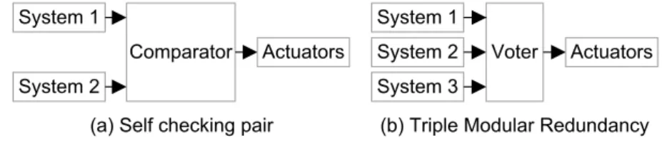
Secondly, instead of simply prioritizing the Backup ADF in case of Primary ADF failure, more sophisticated prioritization function is used to manage their coordinated operation. Such functionality can be achieved using fault-tolerance techniques. Fault-tolerance techniques, in general, use some form of redundancy in the system (e.g., hardware, software) and fault detection techniques to ensure the system output commands are safe. Common fault-tolerant architectures are the self-checking pair and triple modular redundancy (see Figure 1.5).
Figure 1.5: Common fault-tolerant architectures.
To detect faults in the overall system, both architectures in Figure 1.5 rely on differences between the redundant components’ outputs. For example, in the case of the self-checking pair architecture (Figure 1.5, (a)), the outputs of the redundant components (System 1, System 2) are given to the comparator, which compares whether the signals are identical. The comparator requires that the outputs of System 1 and System 2 are the same before any output is sent to the actuators. In the case of triple modular redundancy (Figure 1.5, (b)), a voting block (i.e., voter) collects the outputs from the three redundant components (System 1, System 2, System 3) and compares whether they are identical. The voter requires at least two out of the three systems produce the same output before any output is sent to the actuators.
It is important to note that both comparison and voting approaches work under the assumption that all redundant components show consistent outputs in the absence of faults, also known as replica determinism [5]. In the context
1.1 Problem Statement 7
To avoid such hazardous scenarios, safety experts follow two conventional approaches during the development of the system. Firstly, the system is de-signed considering diversity of the redundant components in order to avoid common cause failures. In the context of ADS, diversity between Primary and Fallback ADFcan be achieved by developing these systems in different teams or companies, with different sensors, algorithms, and hardware, and by use of different programming languages.
Secondly, instead of simply prioritizing the Backup ADF in case of Primary ADF failure, more sophisticated prioritization function is used to manage their coordinated operation. Such functionality can be achieved using fault-tolerance techniques. Fault-tolerance techniques, in general, use some form of redundancy in the system (e.g., hardware, software) and fault detection techniques to ensure the system output commands are safe. Common fault-tolerant architectures are the self-checking pair and triple modular redundancy (see Figure 1.5).
Figure 1.5: Common fault-tolerant architectures.
To detect faults in the overall system, both architectures in Figure 1.5 rely on differences between the redundant components’ outputs. For example, in the case of the self-checking pair architecture (Figure 1.5, (a)), the outputs of the redundant components (System 1, System 2) are given to the comparator, which compares whether the signals are identical. The comparator requires that the outputs of System 1 and System 2 are the same before any output is sent to the actuators. In the case of triple modular redundancy (Figure 1.5, (b)), a voting block (i.e., voter) collects the outputs from the three redundant components (System 1, System 2, System 3) and compares whether they are identical. The voter requires at least two out of the three systems produce the same output before any output is sent to the actuators.
It is important to note that both comparison and voting approaches work under the assumption that all redundant components show consistent outputs in the absence of faults, also known as replica determinism [5]. In the context
8 Chapter 1. Introduction
of AD, the replica determinism can, in general, be expressed as: “the Primary and Backup ADFs shall output consistent driving commands that safely ma-neuver the vehicle on the road”. However, achieving such consistent driving commands is challenging. The rationale for this is the requirement for diver-sity (e.g., dissimilar design, hardware, software) between the redundant ADS’s components (i.e., Primary and Backup ADFs) to cope with common cause fail-ures in a first place. For this reason, the Primary and Backup ADFs will not produce the same output (e.g., trajectories) at the same time, also known as replica indeterminismproblem. The resulting problems of this inconsistency are illustrated in Figure 1.6 (a), (b), and (c).
(a) Inconsistent outputs: both correct
(b) Inconsistent outputs: correct and incorrect
Accident Accident
(c) Inconsistent outputs: all three correct
STOP
Primary ADF 1 Backup ADF 1 Backup ADF 2
Trajectories of shown by
Figure 1.6: Scenarios of inconsistent Primary and Backup ADF outputs.
Figure 1.6 (a) illustrates a case where the Primary and Backup ADFs gen-erate two correct but differing results. Because of that, a simple comparison of Primary and Backup ADFs output (e.g., a self checking pair) will falsely conclude on existing fault (i.e., false positive). Furthermore, the comparison approach will as well not be able to conclude which ADF is faulty or not (see Figure 1.6 (b)). It is a similar matter with fault-tolerant approaches that use majority voting (e.g., triple modular redundancy). As all three (Primary ADF, Backup ADF 1, and Backup ADF 2) are likely to generate different outputs (see Figure 1.6 (c)), no consensus will be reached. Inexact voting or approximate
1.1 Problem Statement 9
agreement algorithms can theoretically solve the replica indeterminism prob-lem. However, these algorithms are proven to be “more complicated due to intransitivity of approximate equality” [6]. Furthermore, inexact voting algo-rithms reduce fault detection coverage [7].
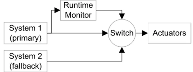
One way to address the replica indeterminism problem in fault-tolerant computing is to use correctness checks for fault detection instead of compar-ison or voting. The dual standby fault-tolerant architecture is one example application of the correctness checks (see Figure 1.7).
Figure 1.7: General dual standby fault-tolerant architecture.
In a typical dual standby fault-tolerant architecture, one of the redun-dant systems is assigned to be the Primary (i.e., System 1) and the other the Backup(System 2). The architecture has a runtime monitor block that verifies the correctness of the Primary system based on application-specific knowledge about how the system may fail. The result of the verification is then given to the switch. If the Primary system is identified to be in a failure state, the switch en-gages the Backup system, and thus Backup system’s commands are forwarded to the actuators.
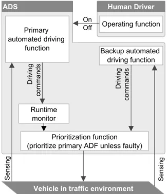
Figure 1.8 depicts an example of adopting the dual standby fault-tolerant ar-chitecture to the ADS arar-chitecture described earlier in Figure 1.3. The runtime monitor verifies the correctness of the Primary ADF. Based on the verifica-tion results, the prioritizaverifica-tion funcverifica-tion (equivalent to the switch) prioritizes the Primary or Backup ADF driving commands. If the verification has been successful (i.e., the Primary ADF concluded to be correct), the prioritization function forwards the Primary ADF driving commands to the actuators. In case the Primary ADF verified to be in failure mode, the prioritization func-tionswitches to the Backup ADF and forwards its driving commands to the actuators. Moreover, to avoid switching to a faulty backup system, the runtime monitorcan also check for faults in the Backup ADF.
1.1 Problem Statement 9
agreement algorithms can theoretically solve the replica indeterminism prob-lem. However, these algorithms are proven to be “more complicated due to intransitivity of approximate equality” [6]. Furthermore, inexact voting algo-rithms reduce fault detection coverage [7].
One way to address the replica indeterminism problem in fault-tolerant computing is to use correctness checks for fault detection instead of compar-ison or voting. The dual standby fault-tolerant architecture is one example application of the correctness checks (see Figure 1.7).
Figure 1.7: General dual standby fault-tolerant architecture.
In a typical dual standby fault-tolerant architecture, one of the redun-dant systems is assigned to be the Primary (i.e., System 1) and the other the Backup(System 2). The architecture has a runtime monitor block that verifies the correctness of the Primary system based on application-specific knowledge about how the system may fail. The result of the verification is then given to the switch. If the Primary system is identified to be in a failure state, the switch en-gages the Backup system, and thus Backup system’s commands are forwarded to the actuators.
Figure 1.8 depicts an example of adopting the dual standby fault-tolerant ar-chitecture to the ADS arar-chitecture described earlier in Figure 1.3. The runtime monitor verifies the correctness of the Primary ADF. Based on the verifica-tion results, the prioritizaverifica-tion funcverifica-tion (equivalent to the switch) prioritizes the Primary or Backup ADF driving commands. If the verification has been successful (i.e., the Primary ADF concluded to be correct), the prioritization functionforwards the Primary ADF driving commands to the actuators. In case the Primary ADF verified to be in failure mode, the prioritization func-tionswitches to the Backup ADF and forwards its driving commands to the actuators. Moreover, to avoid switching to a faulty backup system, the runtime monitorcan also check for faults in the Backup ADF.
10 Chapter 1. Introduction
Figure 1.8: Dual standby fault-tolerant ADS architecture with a runtime monitor.
While such an architecture solves the problem of unconditional prioritiza-tion of the Backup ADF, as well as the problem of replica indeterminism, it opens new challenges for scientists and practitioners. Firstly, a good under-standing of the system is necessary to be able to develop a runtime monitor that detects system failures. Secondly, the integrity of the runtime monitor is essential for ensuring the automated vehicle safety. Consider a case where the runtime monitordoes not detect a failure in the Primary ADF and thus mis-leads the prioritization function to forward the unsafe Primary ADF driving commands to the actuators. Therefore the runtime monitor should be devel-oped with sufficient quality and safety in mind.
1.2 Scope of the Thesis 11
1.2
Scope of the Thesis
This thesis aims at contributing to the overall automated vehicle safety by de-veloping runtime monitoring solutions for verifying the safe operation of the ADS during runtime. In particular, we propose two Runtime Verification (RV) approaches to be built in a runtime monitoring solution: (i) the Computer Vi-sion Monitor(CVM) and (ii) the Safe Driving Envelope Verification (SDE-V). The former is an example of verification of an internal component of the ADF (i.e., the computer vision functionality). The latter verifies the correctness of the driving commands generated by the ADF.
Furthermore, we propose concepts, methods, and architectures that ad-dress challenges encountered during the subsequent development of the RV approaches (i.e., towards an actual runtime monitoring solution). This in-cludes, (i) estimating the sufficient diagnostic test interval of the RV ap-proaches (in particular the CVM), (ii) addressing the Out-of-Sequence Mea-surements(OOSM) problem in sensor fusion-based ADS, as well as (iii) ar-chitectural solutions for improving the scalability and efficiency of the runtime monitoringsolution.
1.3
Thesis Outline
This thesis is organized in two main parts. The first part provides a summary of the thesis, organized as follows. In Chapter 1, a high-level introduction to ADS, problem statement, and motivation for selecting runtime monitoring as a research topic is given. Chapter 2 presents the research methodology used for conducting the research activities, followed by a definition of the research problems and research goals. Chapter 3 describes the contributions of this thesis and provides an overview of the included papers. Chapter 4 surveys the related work on runtime monitoring. Chapter 5 concludes part one of the thesis with conclusions and future work.
The second part of the thesis consists of a collection of four peer-reviewed research publications that encompass all thesis contributions.
Chapter 2
Research Summary
2.1
Research Methodology
Traditionally, the goal of science has been to explore, develop, and justify the-ories (i.e., principles and laws) that explain or predict given phenomena and at the same time advance the knowledge in a given area. Eventually, such the-ories are used by researchers and practitioners while seeking to design and develop a solution for a given real-world problem. Research, where the solu-tion is designed and developed rather than discovered, is referred to as Design Science Research (DSR). Also known as “sciences of the artificial” [8], “sys-temeering”[9], and “constructive research” [10], DSR is a problem solving method that “seeks to create innovations that define ideas, practices, technical capabilities, and products”[11].
This thesis uses DSR as a method for conducting research studies. Over the years, different DSR processes have been proposed [11–14]. We find the pro-cess proposed by Vaishnavi and Kuechler [14] as most suitable for the research conducted in this thesis. Figure 2.1 presents our adaptation of this process. We include two additional steps before the solution implementation step. In the first step, the real-world problems in the AD safety field are investigated. For that, a thorough study of the state-of-practice and state-of-art has been carried out. As a result, the problem of replica indeterminism in fault-tolerant ADS has been identified (description of the problem provided earlier in Chapter 1).
13
Chapter 2
Research Summary
2.1
Research Methodology
Traditionally, the goal of science has been to explore, develop, and justify the-ories (i.e., principles and laws) that explain or predict given phenomena and at the same time advance the knowledge in a given area. Eventually, such the-ories are used by researchers and practitioners while seeking to design and develop a solution for a given real-world problem. Research, where the solu-tion is designed and developed rather than discovered, is referred to as Design Science Research (DSR). Also known as “sciences of the artificial” [8], “sys-temeering”[9], and “constructive research” [10], DSR is a problem solving method that “seeks to create innovations that define ideas, practices, technical capabilities, and products”[11].
This thesis uses DSR as a method for conducting research studies. Over the years, different DSR processes have been proposed [11–14]. We find the pro-cess proposed by Vaishnavi and Kuechler [14] as most suitable for the research conducted in this thesis. Figure 2.1 presents our adaptation of this process. We include two additional steps before the solution implementation step. In the first step, the real-world problems in the AD safety field are investigated. For that, a thorough study of the state-of-practice and state-of-art has been carried out. As a result, the problem of replica indeterminism in fault-tolerant ADS has been identified (description of the problem provided earlier in Chapter 1).
14 Chapter 2. Research Summary
Figure 2.1: An adaptation of a design science research from [14]. In the second step, a solution for the identified problem has been proposed. Based on the general description and problems formulated in Chapter 1, we fo-cus on runtime monitoring as a solution for addressing the identified problem. The development of a runtime monitoring solution for ADS requires solv-ing a variety of research and engineersolv-ing problems. The solution implementa-tionstep (step 3. in Figure 2.1) is intended to guide through these activities.1.
1The solution implementation step is an iterative process. For example, since not all research problems are known in the very beginning, they can be refined in the later stages of the research once a given know-how is reached. Corresponding research goals are then further defined.
2.1 Research Methodology 15
In step 3.1, research problems are identified. A detailed description of the identified research problems is given in Section 2.2. In step 3.2, research goals are defined. We summarize the research goals in Section 2.3
In step 3.3, solutions are proposed. Figure 2.2, left part, depicts a sum-mary of the proposed solutions in this thesis. We propose two RV concepts, namely the CVM (see Section 3.1.1) and the SDE-V (see Section 3.1.4). More-over, we propose solutions for problems encountered during the further de-velopment of the verification concept (i.e., towards an actual product). For example, we propose the use of Fault Tree Analysis (FTA) to estimate the re-quired Diagnostic Test Interval (DTI2) of the CVM (see Section 3.1.2). We also propose methods for ensuring the correct timestamping of sensor mea-surements in order to solve the OOSM problem in sensor fusion-based ADS (see Section 3.1.3). Finally, we propose an architectural solution for improv-ing the scalability (Section 3.1.5 ) and efficiency (Section 3.1.6) of the runtime monitoringsolution.
Figure 2.2: Proposed solution, implementation status and evaluation. In step 3.4 and 3.5, the proposed solutions are respectively implemented and evaluated. Solutions proposed in DSR are rarely full-grown solutions as the implementation for each would require a dedicated full-scale team and fi-nancial resources. Hence, most of the solutions proposed in this thesis have
2Diagnostic Test Interval (DTI) is the amount of time between the executions of verifications by a runtime monitor.
16 Chapter 2. Research Summary
been evaluated theoretically (see Figure 2.2, right part). For example, the methods for achieving precise measurement timestamps have been evaluated by conducting theoretical performance studies (see details in Paper C).
The main criteria for the technical feasibility of the CVM concept has been noted to be dependent on the requirements for the DTI (see details in Section 2.2.2). Therefore we evaluated the feasibility of the concept theoret-ically by conducting FTA that gave estimates on the required DTI (see details in Paper A).
The conducted FTA for ADS have been evaluated based on feedback from the submitted scientific paper (i.e., reviewers) and internal company (TTTech) safety experts. The evaluation of the proposed scalability and efficiency im-provements has also been feedback based. This time we relied on feedback from internal, as well as on external (i.e., OEMs and Tier 1 companies) experts. As the SDE-V concept gained internal company interest, a dedicated team (including the author) created an experimental setup (i.e., simulation and em-bedded platform) to evaluate the feasibility of the concept (see Paper D). The concept is further being developed and evaluated. The generated road scenar-ios for testing the concept currently sum up to approximately 5 hours (from about 2000 scenarios) of simulated road scenarios.
Finally, in step 3.6 of the solution implementation, conclusions are sum-marized. The outcome of each solution implementation iteration is an artifact, which essentially is a contribution containing new knowledge. This knowledge is then used to advance knowledge in the general and specific field of interest. The artifact can be in the form of constructs, models, architectures, methods, concepts, and instantiations (see Table 2.1).
Table 2.1: A summary of artifact types [14]. Extensive list can be find in [15].
No. Type Description
1 Constructs Terms, notations, definitions, and concepts that are needed for
formulating problems and their possible solutions
2 Models A representation of possible solution to practical problem.
3 Architectures
Describes the internal organization of a computer in an abstract way; that is, it defines the capabilities of the computer and its programming model.
4 Methods Sets of steps used to perform tasks. How-to knowledge.
5 Concepts An idea of how something is, or how something should
be done to solve a a problem of interest
6 Instantiations The realization of the artifact in an environment.
16 Chapter 2. Research Summary
been evaluated theoretically (see Figure 2.2, right part). For example, the methods for achieving precise measurement timestamps have been evaluated by conducting theoretical performance studies (see details in Paper C).
The main criteria for the technical feasibility of the CVM concept has been noted to be dependent on the requirements for the DTI (see details in Section 2.2.2). Therefore we evaluated the feasibility of the concept theoret-ically by conducting FTA that gave estimates on the required DTI (see details in Paper A).
The conducted FTA for ADS have been evaluated based on feedback from the submitted scientific paper (i.e., reviewers) and internal company (TTTech) safety experts. The evaluation of the proposed scalability and efficiency im-provements has also been feedback based. This time we relied on feedback from internal, as well as on external (i.e., OEMs and Tier 1 companies) experts. As the SDE-V concept gained internal company interest, a dedicated team (including the author) created an experimental setup (i.e., simulation and em-bedded platform) to evaluate the feasibility of the concept (see Paper D). The concept is further being developed and evaluated. The generated road scenar-ios for testing the concept currently sum up to approximately 5 hours (from about 2000 scenarios) of simulated road scenarios.
Finally, in step 3.6 of the solution implementation, conclusions are sum-marized. The outcome of each solution implementation iteration is an artifact, which essentially is a contribution containing new knowledge. This knowledge is then used to advance knowledge in the general and specific field of interest. The artifact can be in the form of constructs, models, architectures, methods, concepts, and instantiations (see Table 2.1).
Table 2.1: A summary of artifact types [14]. Extensive list can be find in [15].
No. Type Description
1 Constructs Terms, notations, definitions, and concepts that are needed for
formulating problems and their possible solutions
2 Models A representation of possible solution to practical problem.
3 Architectures
Describes the internal organization of a computer in an abstract way; that is, it defines the capabilities of the computer and its programming model.
4 Methods Sets of steps used to perform tasks. How-to knowledge.
5 Concepts An idea of how something is, or how something should
be done to solve a a problem of interest
2.2 Research Problems 17
Constructsprovide the language in which problems and solutions are de-fined and communicated. “The field of mathematics was revolutionized, for example, with the constructs defined by Arabic numbers, zero, and place no-tation” [11]. Another example is the Unified Modeling Language (UML). Models, use constructs to represent a topic or a solution for a given problem (e.g., a UML database model). Methods define processes for how to solve a given problem and achieve a goal. FTA and failure mode and effects analysis (FMEA) are both methods for conducting a hazard analysis. Concepts are the initial proposal for solving a problem of interest. Last but not least, Instan-tiationsdemonstrate the feasibility of an artifact (e.g., a concept) in a real or prototypical implementation.
The artifacts generated in this thesis are as follows. The two RV approaches (i.e., the CVM and SDE-V) are classified as concepts. Moreover, some arti-facts support the further development of the RV concepts. This includes, two methods. The first is a method for estimating the required DTI of the CVM by means of FTA, and the second is the method for achieving correct sensor measurement timestamping in sensor fusion systems. Finally, we provide two architectureartifacts. The first enhancing the scalability, and the second en-hancing the efficiency of runtime monitoring solution under development. A detailed description of the generated artifacts can be found in Section 3.1.
2.2
Research Problems
Building a runtime monitoring solution requires various challenges to be solved. We classify them into four different groups (see Figure 2.3).
Figure 2.3: Research problems and their classification.
2.2 Research Problems 17
Constructsprovide the language in which problems and solutions are de-fined and communicated. “The field of mathematics was revolutionized, for example, with the constructs defined by Arabic numbers, zero, and place no-tation” [11]. Another example is the Unified Modeling Language (UML). Models, use constructs to represent a topic or a solution for a given problem (e.g., a UML database model). Methods define processes for how to solve a given problem and achieve a goal. FTA and failure mode and effects analysis (FMEA) are both methods for conducting a hazard analysis. Concepts are the initial proposal for solving a problem of interest. Last but not least, Instan-tiationsdemonstrate the feasibility of an artifact (e.g., a concept) in a real or prototypical implementation.
The artifacts generated in this thesis are as follows. The two RV approaches (i.e., the CVM and SDE-V) are classified as concepts. Moreover, some arti-facts support the further development of the RV concepts. This includes, two methods. The first is a method for estimating the required DTI of the CVM by means of FTA, and the second is the method for achieving correct sensor measurement timestamping in sensor fusion systems. Finally, we provide two architectureartifacts. The first enhancing the scalability, and the second en-hancing the efficiency of runtime monitoring solution under development. A detailed description of the generated artifacts can be found in Section 3.1.
2.2
Research Problems
Building a runtime monitoring solution requires various challenges to be solved. We classify them into four different groups (see Figure 2.3).
![Figure 1.1: Summary of levels of driving automation. Based on [1].](https://thumb-eu.123doks.com/thumbv2/5dokorg/4826178.130083/18.718.154.566.616.868/figure-summary-levels-driving-automation-based.webp)


![Figure 2.1: An adaptation of a design science research from [14].](https://thumb-eu.123doks.com/thumbv2/5dokorg/4826178.130083/29.718.180.530.207.650/figure-adaptation-design-science-research.webp)

