Mobile IP Handover Delay Reduction
Using Seamless Handover Architecture
Khalid Eltayb Aldalaty
This thesis is presented as part of Degree of
Master of Science in Electrical Engineering with emphasis on Telecommunications
Blekinge Institute of Technology
August 2009
Blekinge Institute of Technology School of Engineering
Department of Telecommunication Supervisor: Dr. David Erman
Page | 3
Abstract
Seamless communication is becoming the main aspect for the next generation of the mobile and wireless networks. Roaming among multiple wireless access networks connected together through one IP core makes the mobility support for the internet is very critical and more important research topics nowadays.
Mobile IP is one of the most successful solutions for the mobility support in the IP based networks, but it has poor performance in term of handover delay. Many improvements have been done to reduce the handover delay, which result in two new standards: the Hierarchical MIP (HMIP) and the Fast MIP (FMIP), but the delay still does not match the seamless handover requirements. Finally Seamless MIP (S-MIP) has been suggested by many work groups, which combine between an intelligent handover algorithm and a movement tracking scheme.
In This thesis, we show the handover delay reduction approaches, specifically the Seamless Mobile IP. The thesis studies the effects of the S-MIP in the handover delay and the network performance as well. A simulation study takes place to compare between the standard MIP and the new suggested S-MIP protocol in term of handover delay, packet loss and bandwidth requirement. The thesis concludes with the analyzing of the simulation results, evaluating the S-MIP performance and finally gives some suggestions for the future work.
Page | 4
Table of Contents
Chapter 1 INTRODUCTION... 8
1.1 Research Motivations………. . 8 1.2 Seamless Communications………. 11 1.3 Research objectives……… 12 1.4 Thesis outlines………12Chapter 2 MOBILE IP PROTOCOL (MIP)……… 13
2.1 Internet Protocol (IP) overview………. 13
2.2 Mobile IP version 4 (MIPv4)……… 14
2.3 Mobile IP version 6 (MIPv6) ………... 16
2.4 Wireless Local Area Networks (WLAN)……….. 19
Chapter 3 HANDOVER DELAY………. 21
3.1 Handover Delay Reasons……….. 21
3.2 Hierarchical Mobile IP (HMIP) ………... 22
3.3 Fast Mobile IP (FMIP)……….. 24
3.4 Seamless Mobile IP (S-MIP) ………... 26
Chapter 4 THE SIMULATION……… 31
4.1 Simulation Goals……….. 31
4.2 Simulation Model………..31
4.3 Simulation Scenario……….. 35
Chapter 5 THE RESULTS………. 37
Page | 5
Chapter 6 CONCLUSION………45
REFERENCES……….46
Appendix……….47
Page | 6
List of figures
Figure 1 Mobile IP version 4 ... 16
Figure 2 Mobile IP version 6 ... 19
Figure 3 Hierarchical Mobile IP ... 23
Figure 4 Fast Mobile IP ... 25
Figure 5 Seamless MIP Architecture ... 27
Figure 6 S-MIP signaling operation ... 30
Figure 7 NS2 Model of Mobile IP Node ... 33
Figure 8 Simulation Network Topology ... 36
Figure 9 Handover delay for standard MIP... 37
Figure 10 handover delay for S-MIP ... 38
Figure 11 link usage for standard MIP ... 39
Figure 12 link usage for S-MIP ... 40
Figure 13 packets loss for standard MIP ... 41
Page | 7
Acronyms
ARP Address Resolution Protocol
BS Base Station
CoA Care-of-Address
CN Correspondent Node
DHCP Dynamic Host Configuration Protocol
DSR Dynamic Source Routing
DSDV Destination Sequence Distance Vector
FA Foreign Agent
FBACK Fast Binding Acknowledge
FBU Fast Binding Update
FMIP Fast Mobile IP
FNA Fast Neighbor Advertisement
FNAACK Fast Neighbor Advertisement Acknowledgment
HA Home Agent
HACK Handover Acknowledge
HI Handover Initiate
HMIP Hierarchical Mobile IP
IETF Internet Engineering Task Force
LCOA On-Link Care-of-Address
L2 Layer 2
L3 Layer 3
MAP Mobility Anchor Point
MN Mobile Node
NAR New Access Router
NOAH NO Ad-Hoc Routing Agent
nFA New Foreign Agent
oFA Old Foreign Agent
PAR Previous Access Router
PrRtAdv Proxy Router Advertisement
RtSolPr Router Solicitation for Proxy Advertisement
SCTP Stream Control Transmission Protocol
SIP Session Initiation Protocol
WLAN Wireless Local-area Access Network
WPAN Wireless Personal-area Access Network
Page | 8
Chapter 1
INTRODUCTION
1.1 Research Motivation
The mobile communications growing very fast, in order to meet today world’s needs and desires. People are moving from one place to another rapidly, changing their attachment points to the communication networks (Mobile Cellular Networks, Wireless Local Area networks WLAN and Wireless Personal Access Networks WPAN). The main challenge produced by this scenario is how to keep those people connected to their destinations, with the minimum delay, while their moving among these different wireless and mobile networks.
The fourth generation (4G) of mobile communication networks will be more flexible for users to communicate anywhere anytime. Using the seamless connection ability can facilitate the access to a large number of networks. 4G represents wireless networks integrated with all existing mobile technologies through a common IP core. It consists of an IP based heterogeneous networks, connected together through an IP core using the Internet. Users will be free to move among these networks, and remain connected to their home networks. IP based networks and mobility management are the main features for the 4G communications. Supporting mobility in IP networks will give the possibility to manage the moving between the various wireless networks connected through the Internet.
The high demand for the real time applications through the Internet is one of the 4G challenges. Real time applications are increasing over the Internet, more and more users are attracted by these kinds of applications, which can be in the form of audio applications, video applications, conference applications, and this is besides the interactive games. Voice over IP (VoIP) and voice chatting services are the major real time applications used in the Internet. Video streaming, radio and TV over the
Page | 9
Internet also are spreading very fast. All these real time applications and others require a high speed connection with a minimum amount of delay.
Reducing the connection delay to satisfy the real time application’s requirements must be considered carefully. The goals of supporting mobility around different wireless and mobile networks (the 4G networks), in addition to reduce the connection delay as less as possible in order to satisfy the real time application’s requirements, are the main focus in this research. We will concentrate mainly in how to reduce the handover delay in the IP layer, specifically the mobile IP (MIP) handover delay using a seamless approach.
1.2 Seamless Communications
Seamless means the user’s free roaming among different networks, and stay connected without any disturbance to the ongoing session. Further more users should not notice the changing of these access networks, which make the handover process from one network to another need to be more sensitive to the handover delay. Considering that each communication session (especially for the real time applications) has its own requirements to be not interrupted by the handover such as the error rate, the delay, the jitter, and the security level.
Most of the wireless networks and the mobile cellular networks are moving to be all IP based. These networks are either connected together through the Internet, or through private IP core networks using the TCP/IP protocol. This opens the door widely to improve the mobility support through the Internet (the TCP/IP stack). TCP/IP was originally designed to manage the communication in the fixed networks; many modifications have been done to support mobility in TCP/IP stack.
A protocols architecture consists of five layers is used in the Internet. The transmission control protocol (TCP), the user datagram protocol (UDP) and the internet protocol (IP) together represent the main protocols known collectively the TCP/IP stack. TCP provides an end to end reliable connection, with control and congestion control ability, while UDP provides an unreliable delivery service. The IP layer is responsible from the routing and delivery of the data among same or different networks.
Page | 10
1.2.1 Mobility supports in TCP/IP stack
Internet mobility support is the keeping of an ongoing communication session without interruption for an IP based mobile device, while it moves from one network to another (changing its point of attachment). Mobility support required handover management, to reduce the service interruption during the handover. Also, it required location management, to identify the mobile device current location, and keep tracking for its movement. In addition, mobility support required multihoming, the mobile device can use many access networks (GPRS, UMTS and WLAN) to access the Internet, and switch links while moving. Finally the security issues, which is one of the important mobility support requirement.
The performance metrics of the network will be affected by the mobility support especially the handover latency, which represent the time between the last received packet from the old network until the first received packet from the new network. The packet loss represents the number of the lost packets during the handover. Signaling overhead and throughput are also performance metrics element which affected by the mobility supporting.
Extensions to the TCP/IP stack to support mobility are necessary; the most successful protocol is that modifying the network layer named as mobile IP (MIP) protocol. Also, some works have been done in the transport layer to support mobility in the TCP, such as the stream control transmission protocol (SCTP), and the datagram congestion control protocol (DCCP). The transport layer is also interacting with the mobility supporting process, trying to remove the dependent on the network layer is the main idea of enabling transport layer mobility support [1]. Session initiation protocol (SIP) is dominating the mobility support in the application layer [1].
The IP address is the addressing and location identifier in the Internet, supporting mobility in the networking layer is the most successful approach; Mobile IPv4 (MIPv4), proposed by Perkins [2], and Mobile IPv6 (MIPv6), proposed by Johnson
Page | 11
1.2.2 Seamless Handover
There are two main types of handover: horizontal and vertical handovers. The horizontal or homogenous handover happen within the same single network. It uses Link layer (L2) information to support mobility. When the received signal strength is getting low a handover will be initiated to connect the mobile device to another transmitter. The vertical handover or heterogeneous handover is happen between different types of networks, using L3, L4 or L5 mobility support. This gives the possibility to the global mobility support.
A combined L2/L3 handover mechanism also can be used to perform both types of handovers. L2 gives the possibility to track the mobile device movement, and help to predict the next access point the mobile will attached to, while L3 provides the ability to roaming between different access networks across the Internet. There are some problems facing this kind of handover; the lack of L2/L3 interaction (cross layer management), L2 and L3 are independently working and there are separate operations for each layer. These problems can be solved using prediction techniques, to enable the mobile node to pre-initiate the handover process, and that by allowing L3 to control certain L2 actions related to the handover, which called the seamless handover approach.
1.2.3 The mobility management
Mobility management has two major elements, location and handover management. Location management is done by the network to discover the current mobile node location besides perform the movement tracking, using location registration, location updating and paging. Only static algorithms are used for location updating, with no adaptation or tracking capability. Using dynamic location updating and paging algorithms will improve the location management performance.
Handover management is also done by the network to keep the mobile node connected while changing its attachment points to the internet. Internet complexity increased recently, mobility nowadays refer to the changing the logical location (point of attachment to the internet), more than just changing the geographical position. Therefore mobility management is turn to more or less a connectivity management procedure.
Page | 12
1.3 Research objectives
The main objective of this research is to study the reducing of mobile IP handover delay, using seamless approach; this will be done in the following steps:
Study Mobile IP delay reduction approaches (Hierarchal MIP, Fast MIP and seamless MIP).
Simulate the Mobile IP protocol and the Seamless MIP protocol using Network Simulator (NS2).
The simulation will study the following performance metrics (the handover delay, the packet loss and the signaling overhead).
Compare the simulation results for MIP protocol and S-MIP approach. Evaluate the Seamless Mobile IP: in term of handover delay, packet loss and
network performance as well, compared to the standard MIP.
1.4 Thesis outlines
The remaining parts of this report will be organized as follow: chapter 2 will discuss the mobile IP protocol, MIPv4 and MIPv6 overview, the mobility management and the signaling operations. Then a description for the WLAN as practical example for the MIP will follow. Chapter 3 will go deeper in the handover delay, reasons and solutions, HMIP, FMIP and S-MIP. Chapter 4 presents the simulation, the simulation model, the simulator and the studied performance metrics. Chapter 5 covers the simulation results, and results analysis. Chapter 6 summarizes the results and concludes the thesis.
Page | 13
Chapter 2
MOBILE IP PROTOCOL (MIP)
2.1 Internet Protocol (IP) overview
The Internet protocol (IP) provides an unreliable, connectionless delivery mechanism. It defines the basic unit of data transfer through the TCP/IP Internet. Also, IP performs the routing function, choosing a path for data transmission. IP includes the rules for the unreliable data delivery: how hosts and routers process packets, how and when error messages should be generated, and which condition packets can be discarded.
IP is responsible from internetwork; interconnects multiple networks (subnetworks) into the internet. Getting the packets from the source and deliver them to the destination, this require the pre knowledge about the network topology, the choice of the suitable path, and the avoidance of congestion, this can be done using IP addressing scheme. IPv4 addresses are 32 bits long, and IPv6 addresses are 128 bits long, some part is reserved for the current IPv4 addresses, and the other part is reserved for the link local addresses, which are not routable and unique on the link. These help nodes on the same link in one local network to communicate using their link local addresses without the needs for routers. Nodes know each other, the local routers and the network prefix using neighbor discovery protocol, which will be used by the MIP protocol as well, as will be shown next section. The IPv6 neighbor discovery protocol is a much improved version of two IPv4 protocols, the address resolution protocol (ARP) and the ICMP router discovery protocol [3].
The main features of IPv6 are:
The Hierarchical addresses, to reduce the routing table size in the memory. The simple header, for more fast forwarding and routing process.
Page | 14
Security improvement, including the availability of authentication and encryption.
The dynamic assignment of addresses.
2.2 Mobile IP version 4 (MIPv4)
The IETF designed a solution for Internet mobility officially called “IP mobility support” and popularly named mobile IP (MIP). The general characteristics include: transparency to application and transport layer protocols, interoperability with IPv4 (using the same addressing scheme), scalability and security.
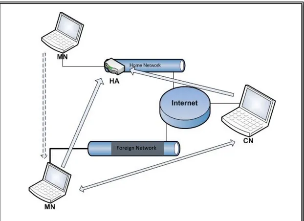
The mobility challenge is how the host will keep its address while it’s moving, without requiring routers to learn host-specific routes. Mobile IP solves this problem by allowing the mobile node to hold two addresses simultaneously. The first is permanent and fixed, it used by the applications and transport protocols. The second is temporary; it changes as the mobile node moves, and is valid only while the mobile node visits a given location. The mobile node gets the fixed (permanent) address on its original home network. Then it moves to a foreign network and gets the temporary address, after that mobile node must send the temporary address to an agent (router) at home network. The agent then will intercept packets sent to the mobile node’s permanent address, and uses encapsulation to tunnel the packets to the mobile node’s temporary address. When the mobile node moves again, it gets a new temporary address, and informs the home agent of its new location. When the mobile node back home, it must contact the home agent to stop intercepting the packets. The mobile’s fixed address is called the home address, because it is assigned by the home network, and it is a same address like that one assigned to a stationary node. When the mobile node connects to a foreign network, it must obtain the temporary address which known as a care of address (CoA), with contact to a router in the foreign network called the foreign agent; the mobile node must first discover the foreign agent, and then contact the agent to obtain the care of address. The care of address is treated like any other address on the foreign network [4].
Finding the foreign agent (foreign agent discovery mechanism) is done by means of the ICMP router discovery procedure. Routers send an ICMP router advertisement message periodically for each other, and a host sending an ICMP router solicitation
Page | 15
to prompt for an advertisement, this process is called the Router discovery mechanism. The foreign agent discovery mechanism added more information to the router discovery message called mobility agent extension. This will allow the foreign agent to advertise its existence and the mobile node to solicit the advertisement [2]. After the mobile node registers with an agent on the foreign network, it must also register with its home agent requesting to forward packets to it care of address. The mobile node sends registration requests to the foreign agent, which forwards it to the home agent.
A Mobile node communicates with other nodes using the following procedure: when the MN sends information to another node, the packets follow the shortest path from the foreign network to the specific destination. The reply will not follow the same route, packets are sent to the mobile’s home network first to the home agent, which has registered the mobile CoA. Second the HA intercepts the packets to distinguish its destination address, and then it encapsulates and tunnels the packets to the care of address. This care of address on the outer datagram specifies the foreign agent, which receives the packets from the home agent, decapsulate them, and then checks its registered mobiles table, and finally transmits the packets to the correct mobile node. When the mobile node moves to a foreign network and wants to communicate with another node near to the foreign network this causes a delay problem called the triangular routing. Each packet sent to the mobile node travel across the internet to the mobile’s home agent which then forwards the packets back again at the foreign network. The problem can be solved using a host specific route, which can be propagating to the nodes near the FAs; this can help eliminating the delay.
Page | 16
Figure 1 Mobile IP version 4
2.3 Mobile IP version 6 (MIPv6)
MIPv6 is the modified version of MIPv4, in order to match IPv6 requirements. It has the same protocol architecture as MIPv4, with some differences in the foreign agent discovery process, care of address registration, security and encapsulation enhancement.
Three IPv6 addresses will be assigned to the mobile node: the permanent home address, the current link local address and the care of address, which is associated with the mobile node’s home address, only when it is visiting a foreign network. The network prefix of the care of address will be similar to the foreign network prefix, and therefore all packets destined to this care of address will be directly forward to the mobile node.
Page | 17
While the mobile node moves from one network to another, the care of address must be configured using stateless address auto configuration or stat full address auto configuration (DHCP) according to the IPv6 neighbor discovery protocol. Mobile node’s home address is associated with its CoA, which is known as a binding, MIPv6 is using a binding cache as a central data structure collected by each IPv6 node. After the mobile node has registered its care of address with a home agent, the home agent uses proxy neighbor discovery to intercept IPv6 packets destined to the mobile node home address, and tunnel them to the mobile node’s care of address using IPv6 encapsulation [3].
MIPv6 gives the opportunity to other nodes to communicate directly with the mobile node; a correspondent node will learn the mobile node’s binding, adds this binding to the binding cache, and when it sends packets to the mobile node, it forwards them to the mobile node’s care of address indicated in the binding (this is similar to the existing MIPv4 route optimization).
In order to communicate with the mobile node in the future, the MN registers its CoA with it’s HA, and informs correspondent nodes (CNs) with its binding to create or update their binding cache, which know as the binding update. A binding acknowledgement is sent by a node acknowledging that it receives the binding update. The binding acknowledgement is sent directly to the mobile node, the destination address of the packets carrying the acknowledgement must be the mobile node’s care of address which can be known from the binding update message. After receiving the binding update and registering it to the binding cache, the correspondent node (CN) can directly sends packets to the mobile node without the need for forwarding the packets first to the mobile node’s home agent. This procedure will help to eliminate the triangular routing problem, which generates longer delay to the packets delivery process [3].
A Mobile node must be able to: execute IPv6 decapsulation, send binding updates and receive binding acknowledgment. The same rules apply to the correspondent nodes [3].
Page | 18
In the home network, the mobile node finds out new routers using router discovery protocol based on received routers advertisements messages. The IPv6 neighbor discovery protocol is used by MIPv6 for movement detection as mentioned before. Away from home, mobile node selects one router from the default routers list to be used as a default router, and when the router become unreachable, mobile node must switch to another default router.
In the wireless communication case, the mobile node is usually connected to the internet through multiple points of attachments or multiple access routers (wireless coverage overlap). The mobile node will accept packets at its old care of address even after the setup of its new care of address and report it to the home agent, this makes the handover process smoother among the access routers.
MIPv6 is more supporting for security, using IPv6 some security specifications should be considered; authentication required to be implemented by all IPv6 nodes, so the mobile node will be able to send authenticated binding updates.
MIPv6 adds more overhead than MIPv4, because the sending of a binding update not just to the home agent but also to all the correspondent nodes (CN) that the MN will connect to them. There is also extra overhead produced from the binding acknowledgement exchange. All this extra overhead will affect the handover delay for the mobile node while it’s moving, and probably increasing the handover delay.
Page | 19
Figure 2 Mobile IP version 6
2.4 Wireless Local Area Networks (WLAN)
WLAN is spreading very fast, because it has the ability to support mobility using wireless coverage and MIP protocol, its flexibility and its fast installation. WLAN products use the free industrial, scientific, and medical (ISM band, 2.4 GHz), which makes the owners, operators and users do not need permission for deploying the service and using it.
IEEE 802.11 is the most famous WLAN standard; it takes in specifications for medium access and radio transmission technology for ISM based WLAN: the MAC layer protocol, the physical layer protocol and also it offers same interface to upper layer protocols as regular 802.x LANs (Ethernet) [5].
Page | 20
Wireless LAN offers high data rates, it reaches up to 54Mbps (the highest data rate provided by a wireless network for indoor applications). Wireless LAN supports a layer 2 handover when the mobile node switches from one access point to another. MIP is used among the IP core connected WLAN access points to perform the handover process. MIP is working independently for link layer (L2) technologies which cost more overhead to perform the handover; in the WLAN when the mobile node moves from one access router to another it first perform a link layer handover (according to the signal strength procedure), then the MIP handover will take place, which will require another time to be setup and to continue the ongoing communication.
In WLAN L2 handover is used to change access routers, which cause interruption for the transmitted data (L2 handover delay). Layer 2 handover is needed the following: movement detection, searching for new access router and reconnection. The mobile node, the old access router and the new access router are the participating nodes in the handover process. Then the L3 MIP handover will start because the mobile node can just communicate with the foreign agent with the same link. MIP handover involves two processes: agent discovery and agent registration as mentioned before [6].
In order to support high speed movement, and real time connection in WLAN an improvement to the handover process should be done, next chapter will discuss MIP handover delay reduction approaches, with focus of combined L2 and L3 handover approach named as seamless MIP.
Page | 21
Chapter 3
HANDOVER DELAY
3.1 Handover Delay Reasons
A mobile node (MN) using MIP to support mobility will perform several tasks exchanging information and signaling with the Home Agent (HA) and the Foreign Agent (FA): after it moves, a mobile node must detect that it has moved, communicate across the foreign network to obtain a secondary address, and then communicate across the internet to its home agent to arrange packets forwarding. It requires considerable overhead after each move.
Handover delay is the time that taken for redirecting the ongoing connection, when the mobile node changes its attachment point from one to another. The handover delay is comprised of two distinct delays: First the time taken for the HA registration process, named as registration delay. Second the time that taken for MN to configure a new network care of address in the foreign network called address resolution delay, both combined represent the overall handover delay in mobile IP (MIP).
Delay reduction solutions are mainly focus to reduce the HA registration delay and the FA address resolution delay. Hierarchical network structure approach is suggested to minimize the registration delay using hierarchical handover. For the address resolution delay, an address pre-configuration is suggested to minimize the delay time using fast handover approach. A combined hierarchical and fast approach also is suggested to improve the performance of mobile IP [7].
The approximate handover delay of 300 to 400 millisecond observed by many studies [7]. This means that the packet loss for the IP layer handover process is still not sufficient to handle the real time applications.
Page | 22
3.2 Hierarchical Mobile IP (HMIP)
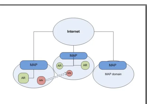
The hierarchical approach separates the mobility support management to micro mobility (intra domain) and macro mobility (inter domain). The mobile node can move inside a specific domain with no need to inform the Home Agent, as long as it moves inside that domain.
A new conceptual entity named Mobility Anchor Point (MAP) is used to support the hierarchical structure. MAP is a router that maintains the binding process with the mobile nodes currently visiting its domain. It is usually located in the network’s edges controlling many access routers, and receives packets on behalf of the mobile nodes inside its domain. When the mobile node moves to another network’s domain it must register itself with the MAP serving that network domain.
The function of the MAP is to act as a Home Agent for the mobile node. So it intercepts the packets targeted to the mobile nodes address inside its domain and then tunnels them to the correspondent care of address of the mobile nodes in their foreign network. When the mobile node changes its care of address inside the MAP domain, it just needs to register this new address with the MAP and this called Local care of address (LCoA). When the mobile node moves to a new MAP domain, it must acquire a new regional care of address (RCoA) to receive packets from outside the domain and also LCoA for inside domain movement.
The mobile node will use the MAP’s address as an RCoA, and it gets the LCoA from the Foreign Agent. After forming the address the mobile node sends a binding update to the MAP, which will bind the mobile node’s RCoA to its LCoA. Then the MAP will send back a binding acknowledgement to the mobile node informing the successful registration. Another binding update should be also sent to the mobile node’s Home Agent every time it changes its RCoA.
The frequency of the home agent registration will be reduced, because the hierarchical structure helps to minimize the location update signaling. Using HMIP, the mobile node just needs to perform home agent registration when it changes the entire MAP domain. As long as the mobile node moves inside the MAP domain, the
Page | 23
HA registration will be avoided. This procedure will minimize the overall handover delay by reducing the HA registration delay [8].
Page | 24
3.3 Fast Mobile IP (FMIP)
The fast handover approach reduces the handover delay by reducing address resolution delay. The mobile node will pre-configure a new care of address before it moves to a new network. In the fast handover the mobile node moves among access routers which defined as the last router connects the wired network to the wireless network. The old access router (oAR) is the router to which the mobile node is currently connected, and the new access router (nAR) is the router to which the mobile node is planning to move. Fast handover uses the wireless link layer (L2) trigger which informs the mobile node that it will soon need to perform a handover. The L2 indication mechanism predicts the mobile node’s movement according to the received signal strength.
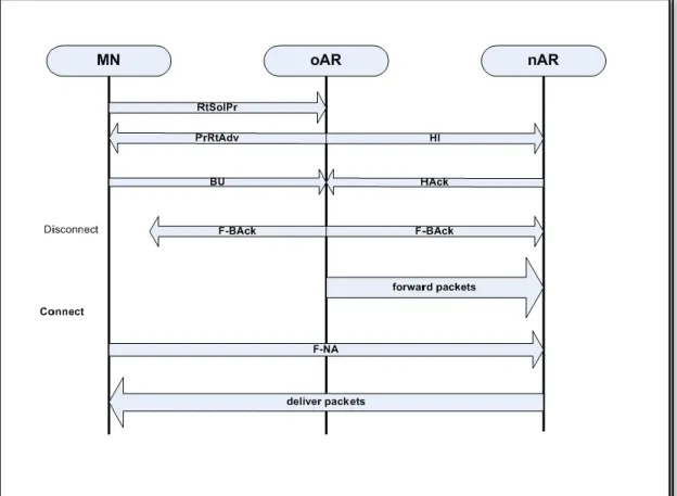
Seven additional messages between the access router and the mobile node will be introduce by the fast handover: the Router Solicitation for Proxy (RtSolPr) from the MN to the oAR, the Proxy Router Advertisement (PrRtAdv) from the oAR to the MN, Handover Initiation (HI) from oAR to nAR and Handover Acknowledgement (HAck) from nAR to oAR. Besides Fast Binding Acknowledgement (F-BAck), Fast Binding Update (F-BU) and Fast Neighbor Advertisement (F-NA). To initiate a fast handover process in a wireless LAN first the mobile node sends RtSolPr message to the oAR after it notices the need for a handover; the link layer address is sent to the next access node by the MN with RtSolPr message. The oAR response with PrRtAdv message, which contains some information about the new point of attachment if it is: known, unknown or connected to the same access router. If the new point of attachment known to the oAR, (PrRtAdv) message will specify to the mobile node the network prefix that should be used to form the new care of address. After forming the new care of address using stateless address configuration, mobile node sends fast binding update (F-BU) to the oAR as the last message before performing the handover, and then a fast binding acknowledgement (F-BAck) will be sent either by the oAR or the nAR to the mobile node to insure a successful binding, the oAR will send duple F-Back messages to the nAR as well. When the mobile node moves to a new network, it sends a fast neighbor advertisement (F-NA) to initiate the packets forwarding from the nAR [9].
Page | 25
To facilitate packet forwarding, oAR and nAR will exchange some messages between them, which result in reducing the address resolution delay. The oAR sends a handover initiation message (HI) to the nAR, requesting a new care of address registration for the mobile node and also it contains the old mobile node’s care of address. The nAR will response by sending handover acknowledgment (HAck) to declare accepting or rejecting the new CoA. Temporary tunnel will be set by the oAR to the new CoA if the nAR accepts the new CoA. Otherwise the oAR will tunnel the packets to the nAR temporarily if it rejects the new CoA, which will take care of forwarding the packets to the mobile node.
More than one study shows that using hierarchical and fast mobile IP together will effectively reduce the overall handover delay to around 300 to 400 milliseconds, which is still not sufficient for offering seamless handover requirements [7].
Page | 26
3.4 Seamless Mobile IP (S-MIP)
The seamless handover architecture is based on both a hierarchical network architecture and fast handover algorithm using wireless link information. In addition S-MIP introduces a new intelligent handover mechanism.
The main goals which S-MIP as trying to are:
A handover delay that is similar to L2 handover delay (in order of tens milliseconds).
Reducing the protocol’s signaling, no more overhead than that for the combined hierarchical and fast approaches.
Minimize the packet loss due to the handover delay.
Packets losses mainly occur for two reasons: one is the segment packets loss which happens between the access router and the MAP. The other reason is the edge packet loss occurs between the mobile node and the last access router. The edge packet loss is due to the mobility and transmission errors, and the segment loss is due to the unpredictable nature of the handover which sometimes results on switching the data stream at the MAP while it receiving a binding updates. S-MIP aims to reduce both kinds of packet losses; edge packet loss is minimized by locating the MAP as close to the mobile node as possible, it’s better to be located at the access router that connects the wireless network to the wire network. Segment packets loss is minimized by using a new suggested entity called Synchronized-Packet-Simulcast (SPS). The SPS broadcasts packets to both the current network of the mobile node besides the new network that the mobile node willing to move to it. S-MIP is using hybrid handover mechanism; the mobile node which has the best knowledge about its current location and its received signal strength will initiate the handover process, then the network system will be responsible for determining the point of the following attachment. This decision is a decision from the movement tracking mechanism, which classified the mobile node movement as one of three modes: either linearly, stochastically or stationary at the middle of two overlapping access routers. The movement tracking procedure will not use additional hardware infrastructure, instead the access routers and the received signal strength will be used to perform the location tracking process.
Page | 27
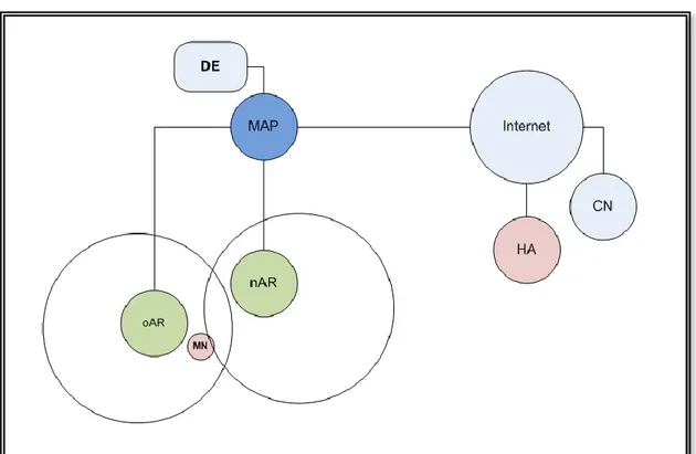
S-MIP network architecture is hierarchical base adding a new entity named decision engine (DE). Like in hierarchical handover the Mobility Anchor Point (MAP) divides the network to domains to manage the mobility as macro or micro mobility.
Figure 5 Seamless MIP Architecture
The decision engine (DE) controls the handover procedure on its network domain, and take the handover decisions. The DE keeps a global view of the network, and tracking all the mobile devices in its network domain in order to identify the movement modes of the mobile nodes. This will be done through periodical messages from the access routers. The DE also offers load balancing by connect the mobile node to the lower load access routers.
S-MIP adds six new messages: Current Tracking Status (CTS) message from the MN to DE, which contains location tracking information. Carrying Load Status (CLS) message from the ARs to DE, which contains the information regarding how many mobile nodes an AR is currently managing. Handover Decision (HD) message from the DE to ARs, which contains the handover decision at the DE, namely which AR a MN should handover to. Handover Notification (HN) message from the oAR to MN, which contains the indication from the oAR to the MN, directing which nAR the MN
Page | 28
should handover to. The oAR derives the content of the HN message from the received HD message. Simulcast (Scast) message from oAR to MAP. The Scast message starts the SPS process. Simulcast Off (Soff) message from nAR to MAP. This message terminates the SPS process [10].
The Seamless handover starts when the mobile node wants to move to a new network, then it will receive beacon advertisement messages from the new access router, the MN will initiate the handover by sending RtSolPr message to the oAR. Then the oAR will send HI messages to all the potential nARs identified by the MN in the RtSolPr message. The HI message will contain the requested care of address on the nAR and the current care of address of the oAR. The nARs will respond by HAck message accepting or rejecting the new care of address. In the case of the nAR accepting the new CoA, the oAR sets up a temporary tunnel to the new CoA. Or in the other case the oAR tunnels the packets to the nAR, which forwards them to the MN temporarily. Similar to the hierarchical handover the MN will receive PrRtAdv message from the oAR.
All access routers send CLS messages to the DE periodically every three seconds, which is reply to the router advertisement messages sent by the DE. The CLS message indicates the numbers of mobile nodes were connected to the access router and their IP addresses. The MN sends CTS message to the DE when it receives link layer beacon advertisement from a new access router. The CTS message contains information about the signal strength of the new access router. This information will be used for location tracking, ARs forward CTS every second until it receives an HD message from the DE. The DE analyzes CTS and CLS messages in order to track the mobile node movement, and then the DE tacks the decision and sends HD message to all participating ARs. Then the oAR will send HN message to the MN to indicate the next AR that the MN must handover to.
According to the movement tracking the seamless handover will follow one of three procedures:
The first procedure is stochastic movement mode, here the DE, using an HD message, will inform the ARs to be in anticipation mode. In this mode the mobile node will not be associated with an AR, but the AR will keep the MN’s binding to be
Page | 29
ready if the MN returning, which will reduce the unnecessary re-setup delay. The HN message from oAR to the MN indicates that the MN will switch network freely, just using fast neighbor advertisement F-NA message. The DE sends HD message to any AR if it indicates that it no longer involves requiring ending the anticipation mode. The second procedure is stationary mode; here the MN will be stationary state between two ARs coverage areas. The DE using HD message will start multiple bindings between the MN and the ARs, which enable the MN to use more than one CoA at the same time.
The third procedure is linearly movement mode; here the HD message contains the AR to which the MN wills handover to. Another HD message will be sent to the rest of the ARs that are not selected by the DE.
Then the MN will just need to send F-BU message to the oAR after it receives the HN message and form the new CoA, in order to bind its current on link address to the new CoA. Then the oAR will send the Scast message to the MAP to initiate the simulcasting of the packets, which mean the duplication and sending the packets to both the oAR and the nAR at the same time. The oAR will send the F-BAck message to both the current and the new networks to ensure that the MN receives its message. After receiving the F-NA message the nAR starts forwards packets to the MN, at the time the oAR is also forwarding packets to the nAR, and sending all the packets on the wireless channel to ensure the reception by the MN in case it does not switch networks immediately. Then nAR will send Soff message to the MAP after it forwards all the packets sent by the oAR to the MN. The MAP then updates binding of the new on link address of the MN with its regional CoA. The Soff message will be forwarded to the DE, which will not allow the mobile node to execute another seamless handover before the current one is completed [7].
Some modifications to the standard router advertisement message must be done. Similar to hierarchical handover the MAP discovery option added to the router advertisement message enabling the MN to discover the MAP. The DE reply option also must be added to the router advertisement, in order to synchronize the timing of the CLS message from ARs to the DE. This synchronization of CLS messages in
Page | 30
addition to the periodic CTS messages is important to the calculation of the movement tracking and also to the handover algorithm.
Figure 6 S-MIP signaling operation
Page | 31
Chapter 4
THE SIMULATION
4.1 Simulation Goals
The simulation process has been done in the following steps: first building the simulation model of the mobile IP network, second implement the mobile IP model in a computer program (Network Simulator NS2), third run the program and get the performance matrices, finally analyze the results according to the protocol behavior in the network system.
In order to evaluate the mobile IP handover delay reduction approaches we will study the network performance using the simulation tool. The main goals of the simulation is study of the effects of the Seamless MIP scheme on the handover delay of an end to end UDP communication session, and then compare it to the handover delay for the standard MIP.
The network Simulator NS-2.33 allinone package was used to simulate the network topology shown in figure 8.
4.2 Simulation Model
NS2 supports wireless and standard MIP protocol, provided by the CMU Monarch's model [12]. In this model mobile nodes are independent; each one has one or more interface to the wireless channel. The main function of the channel is to distribute the packets to all the network interfaces, which is using the radio propagation model to know if they are able to receive the packets. There are also gateways between the wired and wireless nodes named a base station (BS) node to facilitate packets routing between wired and wireless networks [11], [12].
Page | 32
The wireless and mobility extension in NS2 contains the following elements:
The physical layer: The radio propagation model, which includes the free space
model and the shadowing model. The antenna model consists of an omni-directional antenna. Finally the network interfaces, which include the shared media interfaces.
The link layer: The model of IEEE 802.11 standard MAC protocol.
The network layer: The dynamic source routing (DSR) model, the destination
sequence distance vector (DSDV) model, the temporally ordered routing protocol (TORA) model and the ad hoc on demand distance vector (AODV) model.
4.2.1 Mobile IP extension
First we used the basic mobile IP extension of NS2 to simulate the standard MIP protocol. The NS2 MIP extension consists of a mobile host MH, a home agent HA and a foreign agent FA. The MH is a mobile node, the HA and FA are BS nodes, the NS2 model for the mobile IP node is shown in figure 7. The HA and FA have registration agent, which sends beacons to the mobile nodes, performs encapsulation and decapsulation, and reply to solicitations from mobile nodes. The MH also have a registration agent, which responds to the beacons and sends solicitations to the HA and FA [12].
The base station nodes broadcast beacons or advertisement messages to the mobile node. The mobile node generates a solicitation message to the BS, which responds with ad message send to the MH. Then the MH uses the address of the BS as a care of address. When the mobile node moves from one network to another it changes the care of address. All the packets which destined to the mobile node will be tunneled by the HA to the mobile node’s CoA.
The basic MIP extension to NS does not consider other handover protocols, the thing made us search for another NS extension, which has more consideration to the other MIP handover delay reduction methods.
Page | 33
Figure 7 NS2 Model of Mobile IP Node
4.2.2 NOAH routing model
NOAH is a wireless routing agent responsible from connecting the base station nodes with the mobile nodes. Noah added some improvements to the basic MIP extension; the support of overlapping coverage area of the base station and improving the handover process using the intelligent selection of foreign agent [13].
4.2.3 Delay Reduction Extension to NS2
In order to simulate the handover delay reduction mechanisms we used the FHMIP extension to NS2, developed by Hsieh et al [14]. The model is based on the standard MIP and NOAH extensions. The new additions are the MAP agent and the Fast handover functionality. The MAP agent can be connected to a normal wired node
Page | 34
which makes it play the MAP role as a gateway between the mobile node’ HA and FA. The MAP receives the tunneled packets from the HA and then forward them after decapsulation encapsulation processes to the FA.
In this simulation we modified the FHMIP extension to be able to work for NS2.33 allinone package, and to make it more suitable to simulate the S-MIP protocol. HA, oAR and nAR are sending advertisements beacons (ad) every second, when the MN receives the ad messages it registers with the sending base station node, then the MN propagates the registration to the HA.
The mobile node behavior when it reaches the range of the nAR:
Standard MIP: as long as the MN receives advertisements ad messages from the
oAR, it ignores the ad messages from the nAR. When the MN loses the connection with the oAR (3 seconds time out) the MN sends a registration request to the nAR and then changes its CoA.
HMIP: the MN registration is updated every second and propagated to the MAP and
HA, as long as the MN moves inside the domain of the MAP no need to reregister with the HA every single time.
FMIP: the MN registers itself with the nAR immediately after receiving a new ad
message from it. First the MN sends RTSOLPR message to the oAR, which sends HI-HACK messages to the nAR and build a tunnel. The oAR sends PRRTADV message to the MN, which sends a registration request to the nAR and then the nAR forward it to the HA.
The oAR forwards all the MN packets to the nAR. Also it broadcasts them to the medium in the wireless channel. The nAR has no buffering capability, so all the packets reach the nAR before the registration process is completed will be lost.
S-MIP: here we have a mix between the HMIP and the FMIP functionality, when the
MN receives an ad message from the nAR, it sends RTSOLPR message to the oAR. The oAR and nAR exchange HI-HACK messages but do not build a tunnel. The oAR sends PRRTADV message to the MN, which request a registration from the nAR. The nAR forwards the registration request to the MAP which starts forwarding
Page | 35
the packets destined to the MN to the nAR. This will reduce the packets losses because the packets forwarding will not be started until the registration is completed.
4.3 Simulation Scenario
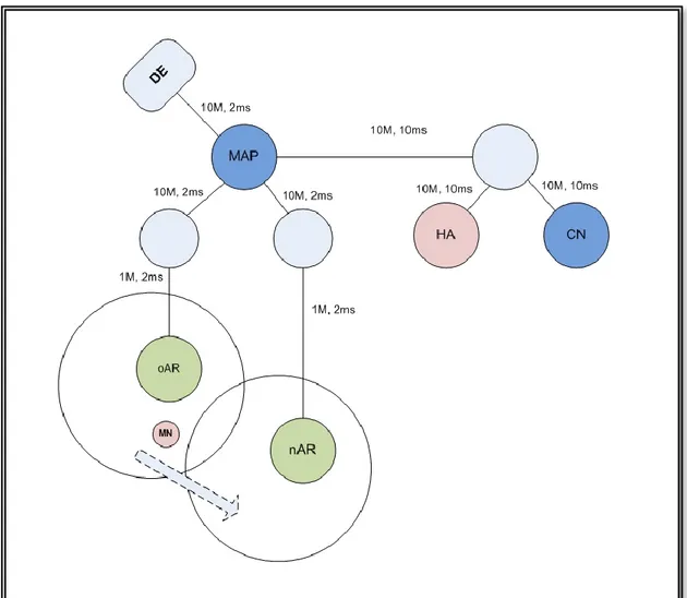
Figure 8 shows the simulated network topology: a hierarchical address is used for all the nodes. There are five domains: the wired node, the correspondent node, the home agent HA, the foreign agent FA and the mobile node. This network topology is the simplest scenario of a mobile IP network topology and it usually used in mobile IP performance evaluations and studies. The link delay (milliseconds) and bandwidth (megabit/seconds) are appeared beside the links, the two access routers are set close together to ensure a partial overlapping between their coverage areas.
In this simulation we only consider a linear movement pattern for the mobile node, the mobile node will move linearly between the access routers from one to another at a constant speed of 1 meter/second.
The simulation scenario begins when the mobile node MN is inside the old access network positioned near to the oAR, and starts a UDP session with the CN. Then the mobile node is moving from the oAR until it reaches the nAR at the end of the simulation time.
A UDP source agent is attached to the correspondent node (CN) and a UDP sink agent attached to the mobile node (MN). The UDP source agent is connected to a traffic generator which is the only source for the ongoing traffic among the network.
Page | 36
Figure 8 The Simulation Network Topology
Page | 37
Chapter 5
THE RESULTS
The simulation results for the standard mobile IP model and for the seamless mobile IP model are shown. The results compare between the handover delay, the bandwidth and the packets loss.
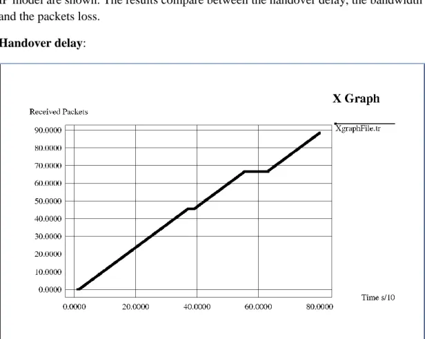
Handover delay:
Figure 9 Handover delay for standard MIP
Figure 9 shows the handover delay for the standard mobile IP, the black line represents the received packets which indicate the mobile node’s (MN) receiving buffer contents. The correspondent node (CN) transmits UDP packets to the mobile node (MN); the line shows the end to end UDP connection versus the simulation time.
From the figure we can notice there were two handover processes during the simulation time: one at t = 37 and the other at t = 55. The first handover happened when the MN moved from the HA to the oAR, and the second handover was happened when the MN moved from the oAR to the nAR (the main simulated handover).
Page | 38
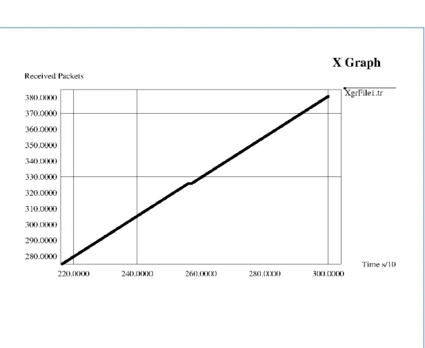
Figure 10 handover delay for S-MIP
Figure 10 shows the handover delay for the seamless mobile IP, the black line represents the received packets which indicate the contents of the mobile node’s (MN) receiving buffer. The correspondent node (CN) transmits UDP packets to the mobile node (MN); the line shows the end to end UDP connection.
From the figure we can notice there was one handover process took place during the simulation time at t = 255. The handover was happened when the MN moved from the oAR to the nAR. The handover delay of the S-MIP case was shorter compare to the standard MIP case (figure 9).
Page | 39
Second the bandwidth:
Figure 11 link usage for standard MIP
Figure 11 shows the link bandwidth in megabit per seconds for the standard mobile IP, the black line represents the bandwidth of the received packets which indicates the mobile node’s (MN) receiving buffer contents. The correspondent node (CN) transmits UDP packets to the mobile node MN, the line shows the end to end UDP connection.
From the figure we can notice there were two handover processes during the simulation time: one at t = 37 and the other at t = 55. The range of the link bandwidth was been about 0.125 and 0.16 Mbps. During the handover processes the link bandwidth was reached to zero, which means there were no received packets by the MN at that time.
Page | 40
Figure 12 link usage for S-MIP
Figure 12 shows the link bandwidth in megabit per seconds for the seamless mobile IP, the black line represents the bandwidth of the received packets which indicates the contents of the mobile node’s (MN) receiving buffer. The correspondent node (CN) transmits UDP packets to the mobile node (MN); the line shows the end to end UDP connection.
From the figure we can notice the handover process during the simulation time: one at t = 255. The range of the link bandwidth was been about 0.125 to 0.16 Mbps the same like in the MIP case. During the handover processes the link bandwidth reached zero, which means there were no received packets by the MN at that time. The amount of the lost bandwidth is reduced by the S-MIP in this case compared to the standard MIP case, and as well the link usage is also being better.
Page | 41
Third the packet loss:
Figure 13 packets loss for standard MIP
Figure 13 shows the packets loss in megabytes for the standard mobile IP; the black line represents the amount of the lost packets from the received packets.
From the figure we can notice there were three points for the packets loss during the simulation time: one at t = 3, t = 38 and the other at t = 55. The lost packets at the first point caused by the first sending of the packets and no handover was involved, it is about 0.00125 Mb. The second point caused by the first handover process and it reach to 0.005Mb, and the last point is also caused by the second handover process and the packets loss reach to 0.018 Mb.
Page | 42
Figure 14 packets loss for S-MIP
Figure 14 shows the packets loss in megabytes for the seamless mobile IP; the black line represents the amount of the lost packets from the whole received packets. From the figure we can notice there was one point for the packets loss during the simulation time: at t = 255. The packet loss at this point caused by the first handover process and it reach to 0.00275Mb, and it’s less than the value of the lost packets for the standard MIP case.
Page | 43
5.1 Result Analysis
To study the seamless mobile IP protocol influence on the handover delay and the network performance as well, we will be focus in the comparison between the standard mobile IP protocol and the seamless mobile IP for the total handover delay, the packets loss and the bandwidth requirements. The total delay involves the layer two (L2) delay, the address resolution time and layer three (L3) handover delay. Using the NS2 the L2 handover time is fixed to 20ms, and the address resolution time, which is the time taken to obtain a new care of address is also fixed to 100ms using NS2.
The UDP session between the CN and the MN starts at the beginning of the simulation, the packet size was 512 bytes and the window size was 32ms. The handover delay was measured using the UDP stream disruption time for the end to end UDP connection, which had been shown in the previous chapter: figures 9 and 10.
In order to approach a confidence interval of 95%, we run the simulation ten times; each time has different five seeds values. This makes the total number of the observations equal to 50 every simulation cycle (observations (n) > 40, normal distribution).
From the simulation results we got the measured handover delay and the packet loss, which will be shown in the table below:
MIP Approach UDP Disruption Time Packets Loss
Standard MIP 600 to 900 ms 0.018 Mbytes
S-MIP 200 to 300 ms 0.00275Mbytes
The simulation results clearly show that the seamless mobile IP approach has better performance in term of handover delay and packets loss compare to the standard mobile IP protocol. The measured handover delay has been reduced about 67% from 600ms to 200ms as minimum, and about 67% also from 900ms to 300ms as maximum values for the total handover delay. The packets loss also has been reduced about 85% from 0.018 Mbytes to 0.00275 Mbytes.
Seamless mobile IP protocol can help efficiently to reduce the total handover delay and the total packets loss which generated from the handover process, but from the
Page | 44
results it still need more efforts to reduce the signaling overhead and to reduce the delay to a value that can meet the real time applications requirements for a seamless handover.
5.1.1 Analytical Calculation for the Handover Delay
Standard Mobile IP:
The total link delay = L2 handover delay + (MN-oAR) delay + (oAR-nAR) delay + 2*(nAR-HA) delay + 2*(MN-nAR)
The total link delay = 20ms + 296ms = 316ms The address resolution delay = 100ms
Total handover delay = 100 + 316 = 416 ms
Seamless Mobile IP:
The total link delay = L2 handover delay + 2*(MN-nAR) delay The total link delay = 20ms + 24ms = 44ms
Total handover delay = 100 + 44 = 144 ms
The analytical calculations also show that the seamless mobile IP has the minimum handover delay compare to the standard mobile IP.
The simulation results also show that the handover delay is still far from the theoretical calculation, and still not sufficient to satisfy the real time applications requirements to support the seamless roaming. Much more effort must be done to reduce the delay further more.
Page | 45
Chapter 6
THE CONCLUSION
The study of many handover delay reduction approaches has been shown by this thesis work. The new suggested seamless mobile IP has considered specifically, and compared to the standard mobile IP protocol.
The simulation results show that the seamless mobile IP has better performance in term of total handover delay, packets loss and bandwidth efficiency as well, compare to the standard mobile IP protocol.
The simulation results also show that the handover delay of 200 ms can be achieved using the seamless approach for end to end UDP connection, which is still not sufficient to satisfy the real time application requirements for a smooth handover process in order to keep an ongoing session without any disruption.
The work in this thesis was focused in the linear movement for the mobile node. We suggest that the future work will be focused more in the random movement and stationary movement for the mobile node. That will give a more accurate evaluation for the seamless mobile IP approach especially for the movement tracking scheme.
Page | 46
References
[1] D. Le, X. Fu, and D. Hogrefe, “A Review of Mobility Support Paradigms for the Internet”, IEEE Communications Magazine, 1st quarter 2006, volume 8, no. 1. [2] C. Perkins, “IP Mobility Support for IPv4”, RFC 3344, Aug.2002.
[3] D. Johnson, C. Perkins, and J. Arkko, “Mobility Support in IPv6”, RFC 3775, June 2004.
[4] “Internetworking with TCP/IP Principles, Protocols, and Architecture”, Douglas E. Comer, Forth Edition, 2000.
[5] “Wireless Communications and Networks”, William Stallings, ch. 13, ch. 14, 2002.
[6] J. Tian, and S. Helal, “Performance of MIP/WLAN in Rapid Mobility Environments”, University of Florida, Gainesville, FL 32611-6120, USA, IEEE Explorer, 2006.
[7] Hsieh, R., Zhou, Z.-G., and Seneviratne, “A. S-MIP: A Seamless Handoff Architecture for Mobile IP”, In Proceedings of INFOCOM, San Francisco, USA, 2003.
[8] Hsieh, R., and Seneviratne, “A. Performance analysis on Hierarchical Mobile IPv6 with Fast-handoff over End-to-End TCP”, In Proceedings of GLOBECOM, Taipei, Taiwan, 2002.
[9] G. Dommety et al., “Fast Handovers for Mobile IPv6”, Internet Draft, IETF, March 2002. Work in Progress.
[10] Hsieh, R., and Seneviratne, “A Comparison of Mechanisms for Improving Mobile IP Handoff Latency for End-to-End TCP”, MobiCom’03, San Diego, California, USA, September 14-19, 2003.
[11]“The Network Simulator – ns (version 2) Website”, http://www.isi.edu/nsnam. [12] “The NS Manual”, http://www.isi.edu/nsnam/ns/ns-documentation.html
[13] S. Yankov, S. Wiethoelter, ”Handover Blackout Duration of Layer 3 Mobility Management Schemes”, TKN Technical Report TKN-06-002, Berlin, May 2006. [14] R. Hsieh,”Fhmip ns extension”, http://mobqos.ee.unsw.edu.au/robert/opcomm/.
Page | 47
Appendix
Mobile IP Simulation Models in NS2
Page | 48
Choice of Communication Delays
Communication Delays used in the Analysis calculations:
Tmn-cn 10-100ms MN-CN Tmn-ha 10-100ms MN-HA Toar-ha 5-95ms oAR-HA Tnar-ha 5-95ms nAR-HA Tmn-oar 2ms MN-oAR Tmn-nar 2ms MN-nAR Toar-nar 10-100ms oAR-NAR TL2 20ms L2-handover