IN
DEGREE PROJECT TECHNOLOGY, FIRST CYCLE, 15 CREDITS
,
STOCKHOLM SWEDEN 2019
SIYA - Slide Into Your
Albums
Design and construction of a controllable dolly
camera with object recognition
SIYA - Slide Into Your Albums
Design and construction of a controllable dolly camera with object recognition
ADAM ALVETEG, KARAM ADEEB
Bachelor Thesis at ITM Supervisor: Nihad Subasic
Examiner: Nihad Subasic
Abstract
The scope of this project is to design, construct and build an automated camera rig with object recognition. The project explores if there are any advantages with an automated camera rig compared to a manual one, how an external camera module can be implemented to track an object and under what circumstances the camera module can register the objects for optimal performance.
The construction is built to travel along a rail of two iron pipes. A camera is mounted on a small wagon that travels on top of the rail with the help of a DC-motor. On the wagon, an external camera module called Pixy2 detects a predetermined object that the user wants the main camera to detect and focus on. Using the feedback data from the Pixy2, two stepper motors run to rotate the main camera horizontally and vertically so that the object is placed in the middle of the frame while the wagon travels along the rail.
Keywords: Mechatronics, Pixy2, automated, color
Referat
Konstruktion av en automatiserad
kamerarigg med objektigenkänning.
Syftet med detta projekt ¨ar att konstruera och bygga en au-tomatiserad kamerarigg med objektigenk¨anning. Projektet unders¨oker om det finns n˚agra f¨ordelar med en automati-serad kamerarigg gentemot en manuell, hur en extern ka-meramodul implementeras f¨or att kamerariggen ska kunna f¨olja ett objekt och under vilka f¨orh˚allanden kameramodu-len registrerar objekten b¨ast.
Kamerariggen ¨ar byggd f¨or att ˚aka l¨angsmed en r¨als som best˚ar av tv˚a j¨arnr¨or. En filmkamera ¨ar monterad p˚a en vagn som rullar ovanp˚a denna r¨als och drivs med hj¨alp av en DC-motor. Ovanp˚a vagnen ska en extern kameramo-dul vid namn Pixy2 uppt¨acka ett f¨orbest¨amt objekt som anv¨andaren vill att filmkameran ska fokusera p˚a. Med hj¨alp av ˚aterkoppling av datan som Pixy2 registrerar styrs tv˚a stycken stegmotorer som antingen roterar filmkameran ho-risontellt i x-led eller vertikalt i y-led tills objektet ¨ar pla-cerat i mitten av Pixy2’s synf¨alt. P˚a detta s¨att kommer konstruktionen att fokusera p˚a objektet samtidigt som den r¨or sig i sidled p˚a r¨alsen.
Nyckelord:Mekatronik, Pixy2, automatiserad, bildigenk¨anning,
Förord
Vi vill tacka v˚ar handledare Nihad Subasic f¨or allt st¨od och all hj¨alp under projektets g˚ang. Vi vill tacka Staffan Qvarnstr¨om som f¨orsett oss med komponenter, elektrisk utrustning och kunskap. Vi vill ¨aven tacka Seshagopalan Thorapalli Muralidharan f¨or alla tips och all hj¨alp, speciellt under konstruktionsfasen. Vi vill utbringa ett stort tack till Tomas ¨Ostberg f¨or alla tips g¨allande olika konstruktionsl¨osningar, f¨or att ha f¨orsett oss med material och delat sin kunskap och expertis med oss. Slutli-gen vill vi tacka alla studenter i mekatroniklabbet f¨or den goda st¨amninSlutli-gen och all hj¨alp under projektet.
Karam Adeeb och Adam Alveteg Stockholm, Maj 2019
Innehållsförteckning
1 Introduktion 1 1.1 Bakgrund . . . 1 1.2 Projektbeskrivning . . . 1 1.3 Syfte . . . 2 1.4 Avgr¨ansning . . . 2 2 Teori 3 2.1 Mikrokontroller . . . 3 2.2 Stegmotor . . . 3 2.3 Stegmotordrivare . . . 3 2.4 DC-motor . . . 4 2.5 F¨argigenk¨anning . . . 4 2.6 Pixy2 . . . 6 3 Metod 7 3.1 Problemformulering . . . 7 3.2 Elektronik . . . 7 3.2.1 Mikrokontroller . . . 8 3.2.2 Stegmotor . . . 8 3.2.3 Stegmotordrivare . . . 8 3.2.4 DC-motor . . . 9 3.2.5 Pixy2 . . . 94.3 Mjukhet av r¨orelsen . . . 16
5 Diskussion och slutsatser 19
5.1 Diskussion . . . 19 5.2 Slutsatser . . . 21 5.3 Rekommendationer f¨or framtida arbete . . . 21
Referenser 23
Appendices 24
A Appendix 25
A.1 Kod . . . 25 A.2 Produktblad . . . 28
Figurer
2.1 RGB-modellen [13] . . . 5
2.2 HSB-modellen [16] . . . 5
3.1 Kopplingsschema. Bild ritad i Fritzing . . . 8
3.2 F¨ardig konstruktion. Bild tagen med iPhone XS Max. . . 10
3.3 Kamerah˚allarens sektionsuppdelning. Bild tagen med iPhone XS Max. . 11
3.4 Fl¨odesschema, ritad i draw.io . . . 13 4.1 Hur olika gr¨ansv¨arden p˚averkar mjukheten. Graf ritad i Microsoft Excel. 17
Tabeller
4.1 Objektdetektering i olika ljuss¨attningar . . . 15 4.2 Detektering av olika f¨arger . . . 16
F¨
orkortningar
CCC Color Connected Components
BSD BasicStepperDriver DC Direct Current
HSB Hue, Saturation, Brightness
IDE Integrated Development Environment PAN-offset Panoreringsavvikelse
PD Proportional, Derivative RGB Red, Green, Blue RPM Revolutions per minute USB Universal Serial Bus
Kapitel 1
Introduktion
1.1
Bakgrund
Inom filmskapande och TV-produktion ¨ar det vanligt att filma sekvenser ur olika vinklar och p˚a olika s¨att f¨or att f¨ormedla budskapet p˚a b¨asta s¨att. Det finns otaligt m˚anga filmtekniker och en vanlig teknik som anv¨ands f¨or att filma ett objekt som exempelvis ¨ar i r¨orelse ¨ar ett s˚akallat dolly-shot. Denna teknik inneb¨ar att filmkam-eran ¨ar fastmonterad p˚a en kameravagn, ¨aven kallad dolly, som g˚ar p˚a r¨als f¨or att f¨orflyttningen ska ske s˚a mjukt och stadigt som m¨ojligt. Dessa kamerariggar brukar vanligtvis styras manuellt genom att en person skjuter vagnen l¨angs r¨alsen medans ytterligare en person sitter vid filmkameran och riktar kameran p˚a objektet som filmas. Denna rapport unders¨oker m¨ojligheten till att automatisera denna teknik genom att driva dolly-vagnen fram˚at med hj¨alp av bland annat stegmotorer och en mikrokontroller. Dessutom unders¨oks m¨ojligheten att f˚a kameran att fokusera p˚a ett specifikt objekt och l˚ata den f¨olja objektet n¨ar dolly-vagnen r¨or p˚a sig.
1.2
Projektbeskrivning
Projektet g˚ar ut p˚a att designa och bygga en kamerarigg som styrs via en Arduino-programmerad mikrokontroller. Kamerariggen ska kunna f¨orflytta sig l¨angsmed en r¨als och ¨aven rotera i b˚ade vertikal- och horisontalled f¨or att filma ett specifikt objekt. Riggen ska med hj¨alp av en extern kameramodul kunna k¨anna igen objektet och p˚a s˚a s¨att automatiskt rikta filmkameran mot det under sj¨alva r¨orelsen.
KAPITEL 1. INTRODUKTION
1.3
Syfte
M˚alet med projektet ¨ar att unders¨oka specifikt tre stycken forskningsfr˚agor som lyder:
• Finns det n˚agra f¨ordelar med en automatiserad kamerarigg gentemot en manuell? • Hur kan en extern kameramodul implementeras f¨or att kamerariggen ska
kunna f¨olja ett objekt automatiskt?
• Vilka f¨orh˚allanden ¨ar mest gynnsamma f¨or att kameramodulen ska k¨anna igen ett objekt?
1.4
Avgränsning
D˚a detta projekt ¨ar begr¨ansat till b˚ade tid och resurser har avgr¨ansningar gjorts. Bland annat kommer objektet som kameran ska filma vara stillast˚aende och inte i r¨orelse. Dessutom kommer kamerariggen att testas under ideala f¨orh˚allande d¨ar exempelvis underlaget som riggen st˚ar p˚a ¨ar plant utan n˚agra oj¨amnheter. Kamer-ariggen kommer ¨aven byggas f¨or att passa enklare filmkameror som systemkameror och mobilkameror och d¨armed inte n˚agra professionella filmkameror.
Kapitel 2
Teori
2.1
Mikrokontroller
F¨or att kunna kontrollera konstruktionen och programmera dess funktioner kr¨avs h˚ardvara i form av en mikrokontroller. En mikrokontroller ¨ar i princip en mini-atyrdator med bland annat en processor som utf¨or ber¨akningar och datahantering och ett arbetsminne som ¨ar tillg¨angligt f¨or processorn d˚a den utf¨or ber¨akningar [1]. I dagens marknad finns ett stort utbud av dessa olika styrenheter och de anv¨ands i huvudsyfte f¨or att antingen styra eller arbeta tillsammans med andra elek-triska komponenter i olika system och konstruktioner. En vanligt f¨orekommande mikrokontroller ¨ar en Arduino som ¨ar ett kretskort med ¨oppen k¨allkod. Mikrokon-trollerkortet har 14 digitala in- och utdatastift som anv¨ands f¨or att ta emot eller skicka information till komponenter som exempelvis sensorer. Till Arduino finns det en integrerad utvecklingsmilj¨o som heter Arduino Integrated Development En-vironment (IDE) som m¨ojligg¨or att kortet kan programmeras och d¨armed styras av anv¨andaren [2].
2.2
Stegmotor
En stegmotor ¨ar en slags likstr¨omsmotor som omvandlar likriktad elektrisk str¨om till mekaniskt arbete med hj¨alp av en kommutator, spolar och magneter [3]. En stegmotor har flertaliga spolar som ¨ar grupperade och dessa kallas f¨or faser. D˚a det matas str¨om genom en av dessa faser f¨orflyttar sig motorn ett steg och genom att g¨ora detta i en sekvens f¨or varje fas kommer motorn att rotera [4]. Hur m˚anga graders vinkel ett steg motsvarar beror p˚a vilken typ av stegmotor som anv¨ands. I och med att motorn kan rotera ett steg i taget kan h¨og precision uppn˚as [5].
2.3
Stegmotordrivare
Stegmotordrivare ¨ar en elektrisk komponent som anv¨ands f¨or att styra stegmotorers drift [6]. Drivaren justerar och reglerar tillf¨orseln av str¨om till stegmotorn och dess
KAPITEL 2. TEORI
faser och d¨armed best¨ammer hur stora steg motorn ska rotera och ˚at vilket h˚all. Det finns fyra olika typer av s¨att som en stegmotordrivare kan sl¨appa igenom str¨om till motorn p˚a. Dessa s¨att ¨ar att endast en fas str¨omf¨ors i taget, tv˚a faser str¨omf¨ors samtidigt, en eller tv˚a faser str¨omf¨ors eller slutligen genom att str¨omf¨ora med hj¨alp av mikrosteg. Beroende p˚avilken ovanst˚aende typ av stegmotordrivare som anv¨ands kommer stegmotorn att erh˚alla olika egenskaper som exempelvis i form av mjukare g˚ang och st¨orre moment [7].
2.4
DC-motor
Likstr¨omsmotor, eller DC-motor, ¨ar en elektrisk motor som omvandlar elektrisk energi till mekanisk energi. Motorns tv˚a huvudkomponenter ¨ar en stator och en rotor [8]. Statorn best˚ar av permanentmagneter och har i uppgift ¨ar att skapa ett konstant magentf¨alt runt rotorn. Rotorn ¨ar positionerad innuti statorn och ¨ar uppbyggd av spolar som str¨om kan fl¨oda genom. D˚astr¨om g˚ar genom rotorn uppst˚ar ett magnetf¨alt och eftersom statorn ¨ar magnetisk attraheras en sida av rotorn och d¨armed skapas en roterande r¨orelse. Med hj¨alp av en kommutator som rotorn ¨ar kopplad till kan det magnetiska f¨altets riktning bytas och d¨armed kan rotorn rotera ett helt varv. Denna process p˚ag˚ar v¨axelvis vilket leder till att motorn roterar fritt till skillnad fr˚an stegmotorn som roterar ett steg i taget d˚a varje fas str¨omf¨ors [9].
2.5
Färgigenkänning
Ljus som m¨anniskor ser det best˚ar av tre huvudf¨arger: R¨od, Gr¨on och Bl˚a som ¨aven f¨orkortas RGB. Dessa tre f¨arger motsvarar i princip de f¨arger som b¨ast uppfattas av v˚ara ¨ogons tappar [10]. Varje f¨arg befinner sig inom det synliga spektrumet och varierar i v˚agl¨angd beroende p˚a f¨argen. Digitala bilder ¨ar uppbyggda utav pixlar d¨ar RGB-systemet spelar en stor roll i och med att varje pixel kan visa en unik f¨arg [11] [12]. Varje RGB-f¨arg i pixeln kan skalas upp fr˚an 0-255 i gr˚askalan, d¨ar 255 ¨ar det h¨ogsta v¨ardet, beroende p˚a hur starkt f¨argen ¨onskas lysa. P˚a detta s¨att g˚ar det att kombinera olika v¨arden och f˚a olika f¨arger, se figur 2.1.
2.5. F¨ARGIGENK¨ANNING
Figur 2.1. RGB-modellen [13]
F¨or att kunna k¨anna igen f¨arger kr¨avs det ett objektsidentifieringssystem som kan detektera pixlar som exempelvis en kameramodul [14]. Med systemet g˚ar det att analysera varje bild som registreras. F¨or att identifiera f¨argen p˚aobjektet analyseras nyansen p˚a objektet i bilderna, f¨argernas m¨attnad och ljusintensiteten i bilderna. Ett s¨att att beskriva f¨arger med dessa tre parametrar kallas HSB - Hue, Saturation, Brightness som visas i figur 2.2 [15].
KAPITEL 2. TEORI
2.6
Pixy2
En kameramodul ¨ar en bildsensor som kan anv¨andas f¨or att detektera b˚ade f¨arger och objekt genom att skicka data till exempelvis en mikrokontroller. En kam-eramodul som ¨ar anpassad f¨or projekt d¨ar en mikrokontroller anv¨ands ¨ar Pixy2. Kameramodulen har en anv¨andarv¨anlig mjukvara som m¨ojligg¨or att enkelt st¨alla in kameran att k¨anna igen specifika objekt och f¨arger. F¨or att s¨arskilja ett speci-fikt objekt anv¨ander Pixy2 en f¨argbaserad filteralgoritm som kallas Color Connected Components (CCC) . Algoritmen ber¨aknar varje RGB-pixels f¨argnyans och m¨attnad som kamerasensorn registrerar och anv¨ander dessa parametrar vid filtreringen [17]. Pixy2 kan lagra upp till sju stycken olika objekt i sitt arbetsminne men med hj¨alp av f¨argkoder g˚ar det att lagra tusentals olika objekt. Pixy2 ansluts enkelt till Arduino Uno med mikrokontrollerns in- och utg˚angsstift [18].
Kapitel 3
Metod
3.1
Problemformulering
F¨or att unders¨oka och besvara forskningsfr˚agorna m˚aste f¨oljande problem l¨osas: • Konstruera och bygga en fungerande kamerarigg
• Beh˚alla filmobjektet i centrum under en filmsekvens
• Genom feedback fr˚an en kameramodul reglera stegmotorernas positioner
3.2
Elektronik
Elektriska komponenter med olika funktioner anv¨ands och kopplas samman f¨or att f˚a kamerariggen att utf¨ora de ¨onskade r¨orelserna. De komponenter som anv¨ands ¨ar en mikrokontroller, tv˚a stegmotorer, en DC-motor, tv˚a stegmotordrivare samt en kameramodul.
KAPITEL 3. METOD
3.2.1 Mikrokontroller
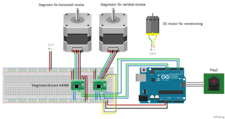
F¨or att styra all elektronik anv¨andes mikrokontrollern Arduino Uno. Samtliga elek-triska komponenter f¨orutom DC-motorn ¨ar sammankopplade till denna mikrokon-troller genom mikrodatorns digitala utg˚angar och till ett kopplingsd¨ack. Kopplin-garna visas i figur 3.1.
Figur 3.1. Kopplingsschema. Bild ritad i Fritzing
3.2.2 Stegmotor
Konstruktionens r¨orelser drivs och styrs av tv˚a stycken stegmotorer. En stegmotor av modellen KH56JM2 roterar kamerah˚allaren horisontellt och en motor av modell RS Pro Hybrid 5350372 m¨ojligg¨or att kamerah˚allaren kan r¨ora sig vertikalt. Anled-ningen till att stegmotorer anv¨andes ist¨allet f¨or DC-motorer beror bland annat p˚a att stegmotorer har ett h˚allmoment som inneb¨ar att trots att motorn inte roterar beh˚aller den ¨and˚a sin position eftersom det fortfarande g˚ar str¨om genom faserna. Denna funktion ¨ar v¨asentlig d˚a kamerah˚allaren ska bibeh˚alla sin vertikala position.
3.3. H˚ARDVARA
3.2.4 DC-motor
F¨or drivning av konstruktionen anv¨ands en DC-motor av modellen Pittman GM9232E311-R1 som har en utv¨axling p˚a 218.4:1. Denna motor driver kamerah˚allaren fram˚at genom att ¨overf¨ora sitt roterande moment med hj¨alp av en kuggremsskiva till en kuggrem som ¨ar fastmonterad p˚a kamerah˚allaren. Denna motor styrs inte av mikrokontrollern utan kopplas separat till en sp¨anningsk¨alla d¨ar hastigheten av motorns rotation best¨ams av sp¨anningen. F¨ordelen med att anv¨anda en DC-motor ist¨allet f¨or en stegmotor till drivningen ¨ar att DC-motorerna ¨ar stegl¨osa vilket g¨or att drivningen blir ¨annu j¨amnare och mjukare.
3.2.5 Pixy2
F¨or att detektera ett objekt som kameran ska f¨olja anv¨ands kameramodulen Pixy2. Genom att koppla Pixy2 till en Arduino kan anv¨andaren se vad kameran ser genom den medf¨oljande mjukvaran PixyMon. I detta program best¨ams dessutom vilket ob-jekt som Pixy2 ska registrera och k¨anna igen genom att ge obob-jektet en signatur [18]. De objekt som kameran har registrerat markerar Pixy2 med ett rektangul¨art block som den sedan kan anv¨anda f¨or att veta objektets position i f¨orh˚allande till kamerans synf¨alt. Pixy2 har ett inbyggt koordinatsystem och kan d¨arf¨or med hj¨alp av f¨orpro-grammerade funktioner ber¨akna x- och y-koordinaterna f¨or objektets mittpunkt. Dessa koordinater kan sedan anv¨andas f¨or att ge ˚aterkoppling till motorerna s˚a att objektets mittpunkt alltid ¨ar i Pixy2’s synf¨alt. Algoritmen f¨or ˚aterkopplingen beskrivs mer i detalj i avsnitt 3.4.
3.3
Hårdvara
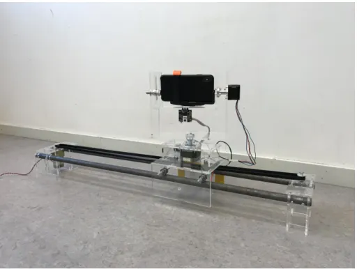
Den slutgiltiga konstruktionen visas i figur 3.2 och kan delas upp i tre olika omr˚aden; kamerah˚allare, r¨als och drivning. Dessa olika sektioner beskrivs separat nedan.
KAPITEL 3. METOD
Figur 3.2. F¨ardig konstruktion. Bild tagen med iPhone XS Max.
3.3.1 Kamerahållare
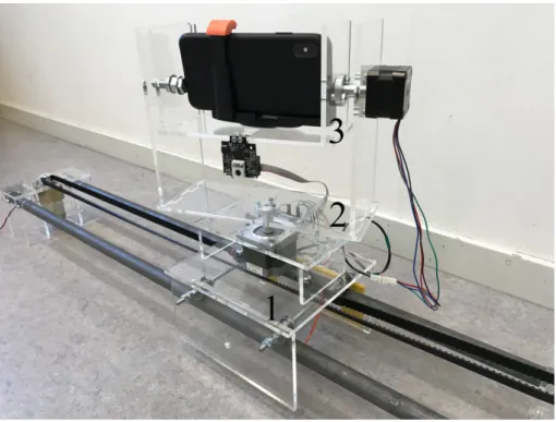
Kamerah˚allaren ¨ar den del som h˚aller filmkameran och de elektroniska kompo-nenterna. H˚allaren ¨ar till st¨orsta del byggd av 5 mm tjock akrylplast d¨ar varje komponent ¨ar laserskuren. Akrylplattorna assembleras sedan p˚a ett pusselliknande s¨att d¨ar varje bit klickas i varandra och sedan fogas samman med aceton. Kam-erah˚allaren kan i sin tur delas upp i tre olika sektioner, se figur 3.3.
3.3. H˚ARDVARA
filmkameran samt kameramodulen f¨astes.
Figur 3.3. Kamerah˚allarens sektionsuppdelning. Bild tagen med iPhone XS Max.
3.3.2 Räls
F¨or att konstruktionen ska kunna r¨ora sig fram˚at p˚a ett mjukt s¨att anv¨ands en slags r¨als som kamerah˚allaren kan r¨ora sig l¨angsmed. R¨alsen utg¨ors av tv˚a stycken j¨arnr¨or med 20 mm i diameter som ¨ar upph¨angda p˚a tv˚a stycken h˚allare gjorda i akrylplast. P˚a undersidan av bottenplattan i sektion ett fr˚an figur 3.3 ¨ar ˚atta stycken kullager monterade som vilar p˚a ovansidan av j¨arnr¨oren och d¨armed g¨or att hela kamerah˚allaren kan glida p˚a dessa. Dessa kullager ¨ar monterade p˚a en 6 mm g¨angad axel tillsammans med brickor och muttrar.
3.3.3 Drivning
F¨or att kamerah˚allaren ska kunna drivas l¨angsmed r¨alsen anv¨ands remdrift som drivning. Mellan kamerah˚allarens bottenplatta i sektion ett enligt figur 3.3 och r¨oren l¨oper en kuggrem som ¨ar monterad p˚a undersidan av bottenplattan. Denna rem ¨ar uppsp¨and mellan tv˚a stycken kuggremsskivor som ¨ar monterade p˚a de tv˚a h˚allarna som j¨arnr¨oren vilar p˚a. Kamerah˚allaren r¨or sig slutligen fram˚at genom att en DC-motor ¨overf¨or sitt roterande moment till remmen. Kuggremmen som anv¨andes var en 10 mm rem med kuggstorlek XL 3/8”.
KAPITEL 3. METOD
3.4
Mjukvara
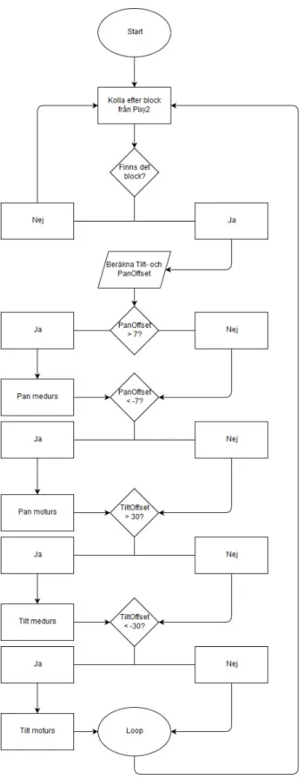
F¨or att programmera Arduino Uno anv¨andes Arduino IDE som ¨ar en mjukvara d¨ar anv¨andaren skriver kod i C/C++ som sedan laddas upp via en USB-kabel till mikrokontrollen. Koden som ¨ar skriven f¨or att f˚a konstruktionen att utf¨ora de ¨onskade r¨orelserna ˚aterfinns i appendix A1.
Kodning av denna konstruktion kan sammanfattas kort genom ett fl¨odesschema enligt figur 3.4 som visar den huvudsakliga funktionen. Programmet kollar efter de block som Pixy2 registrerar fr˚an objektet. I en konstant loop kollar programmet om det finns ett eller flera block inom kameramodulens synf¨alt. D˚a det finns ett block kommer programmet att kolla om blockets centrum ligger inom en angiven gr¨ans fr˚an Pixy2’s synf¨alts centrum i b˚ade horisontellt led (Pan) och vertikalt led (Tilt). D˚a blocket ligger f¨or l˚angt bort justerar programmet detta genom att driva respektive stegmotor tillr¨ackligt m˚anga steg tills objektet ¨ar inom referensomr˚adet. Drivning av stegmotorerna sker genom tv˚a inkluderade bibliotek, BasicStepper-Driver samt A4988 [19]. Biblioteket BasicStepperBasicStepper-Driver (BSD) ger tillg˚ang till olika l¨agen f¨or styrning av stegmotorerna. F¨or denna konstruktion anv¨ands m¨ojligheten att driva stegmotorerna i grader genom att definiera hur m˚anga steg stegmotorn beh¨over ta f¨or att utf¨ora en hel rotation. Biblioteket A4988 ¨ar f¨or stegmotordri-varen som anv¨ands i konstruktionen. Det ger tillg˚ang till att kontrollera med vilket varv per minut (RPM) som b˚ada motorerna ska rotera med, samt kunna st¨alla in mikrosteg.
3.4. MJUKVARA
Kapitel 4
Resultat
4.1
Omgivningsförhållanden
De olika omgivningsf¨orh˚allanden som kan p˚averka kameramodulens f¨orm˚aga att k¨anna igen objekt unders¨oktes i form av att ¨andra ljuss¨attningen i rummet samt att placera andra objekt med liknande signaturf¨arg som kan st¨ora kameramodulen under drift.
4.1.1 Ljussättning
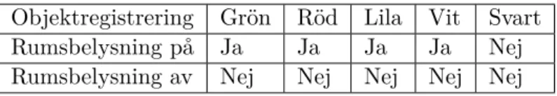
I detta test ¨andrades ljuset i rummet d˚akameramodulen var fokuserad p˚aett objekt. Innan ljuset sl¨acktes skapades en signatur f¨or objektet och kameramodulen hade objektet i centrum av dess synf¨alt. D˚a ljuset sl¨acktes kunde kameramodulen inte l¨angre uppt¨acka objektet och visa dess signatur. Samma test utf¨ordes f¨or samma objekt men i olika f¨arger. Resultatet av detta test redovisas i tabell 4.1.
Tabell 4.1. Objektdetektering i olika ljuss¨attningar
Objektregistrering Gr¨on R¨od Lila Vit Svart Rumsbelysning p˚a Ja Ja Ja Ja Nej Rumsbelysning av Nej Nej Nej Nej Nej
KAPITEL 4. RESULTAT
4.1.2 Färgstörning
D˚a kameramodulen fokuserade p˚a ett objekt placerades ett st¨orningsobjekt med samma f¨arg inom synf¨altet f¨or kameramodulen. St¨orningsobjekten uppt¨acktes, men eftersom det var mindre ¨an huvudobjektet skedde inga st¨orningar under driften av filmsekvensen. D¨aremot skulle ett st¨orningsobjekt med st¨orre signaturarea skapa st¨orningar under k¨orningen. Detta p˚a grund av att kameramodulen ¨ar program-merad att f¨olja det objekt med st¨orst signaturarea.
4.2
Igenkänningsförmåga
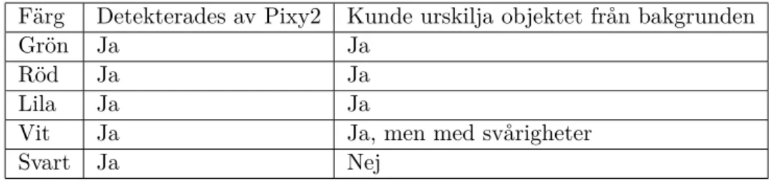
Kameramodulens f¨orm˚aga att k¨anna igen ett visst objekt med en viss f¨arg testades genom att skapa signaturer f¨or ett 3D-utskrivet testobjekt. Detta objekt skapades i fem kopior men med olika f¨arger f¨or att kunna unders¨oka vilka f¨arger Pixy2 l¨att kan k¨anna igen. Enligt tabell 4.2 kunde objektet i starkare nyanser detekteras och registreras b¨attre ¨an det svarta och vita objektet.
Tabell 4.2. Detektering av olika f¨arger
F¨arg Detekterades av Pixy2 Kunde urskilja objektet fr˚an bakgrunden
Gr¨on Ja Ja
R¨od Ja Ja
Lila Ja Ja
Vit Ja Ja, men med sv˚arigheter
Svart Ja Nej
4.3
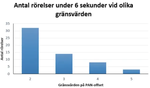
Mjukhet av rörelsen
Mjukheten i en k¨orning testades genom att ¨andra p˚a gr¨anserna f¨or vart objektets centrum skulle placeras inom kameramodulens synf¨alt. Testet utf¨ordes d˚a kam-erariggen stod helt stilla utan att den r¨orde sig l¨angs r¨alsen. D˚a gr¨anserna p˚a m¨atfelet Panorerings-Offset (PAN-offset) var sm˚a hamnade objektet n¨ara mitten
4.3. MJUKHET AV R ¨ORELSEN
Kapitel 5
Diskussion och slutsatser
5.1
Diskussion
De utf¨orda testerna visade att det ¨ar m˚anga olika parametrar som avg¨or hur bra ett objekt kan detekteras och f¨oljas. Enligt resultaten ¨ar det vissa f¨orh˚allanden som ¨ar mer gynnsamma f¨or att detekteringen ska fungera p˚a ett s˚a bra s¨att som m¨ojligt. Dessa f¨oruts¨attningar kan sammanfattas till f¨oljande:
• Rummet ska vara v¨albelyst
• Objektet som ska filmas har en nyanserad f¨arg
• Det inte ¨ar n˚agra andra objekt i bakgrunden som har liknande eller samma f¨arg som huvudobjektet
• En ny signatur skapas innan filminspelning f¨or b¨ast igenk¨anning av objektet D˚a dessa f¨oruts¨attningar ¨ar uppfyllda kan konstruktionen f¨olja objektet och filmin-spelnigen uppn˚ar b¨asta m¨ojliga kvalitet.
En begr¨ansning med kameramodulen ¨ar faktumet att Pixy2 uppt¨acker starka nyanser b¨ast. Detta orsakas av att modulen f¨oljer HSB-modellen. P˚a grund av modellen ¨ar d¨arf¨or kamerariggen d˚alig p˚a att k¨anna igen m¨orka objekt. Vid testerna med m¨orka objekt hade kameramodulen en stark tendens att plocka upp andra m¨orka f¨arger i bakgrunden vilket orsakade starka st¨orningar under en filmsekvens. Detta h¨ande ¨aven d˚a objektet var helt vitt, dock i mindre grad. F¨ormodligen kan detta f¨orb¨attras genom att implementera ett filter f¨or att filtrera ut f¨argerna mer precist och d¨armed detektera och f¨olja objektet b¨attre. Dessutom ¨ar en m¨ojlig l¨osning att skapa fler signaturer av objektet under olika f¨orh˚allanden s˚aatt pl¨otsliga ¨andringar i ljuss¨attningen inte s¨atter Pixy2 ur spel. Allts˚a f˚as den b¨asta igenk¨anningsf¨orm˚agan d˚a objektet ¨ar det enda objektet med sin egna starka och nyanserade f¨arg i ramen f¨or kameramodulen under en filmsekvens.
KAPITEL 5. DISKUSSION OCH SLUTSATSER
Under testet av ljuss¨attningen i kapitel 4 avsnitt 4.1.1 gjordes ingen m¨atning av ljusstyrkan vilket hade givit mer precision i bed¨omningen av igenk¨anningsf¨orm˚agan. De resultat som erh¨olls fr˚an testet gav inte n˚agra svar p˚a vilken ljusstyrka som ¨ar brytpunkten d˚a Pixy2 fortfarande kan k¨anna igen objektet utan det gav endast svar p˚a hur v¨al de olika f¨argerna kunde detekteras i en m¨orkare milj¨o. En f¨orb¨attring av detta test skulle d¨arf¨or vara att m¨ata ljusstyrkan i rummet som testet utf¨ors i f¨or att kunna m¨ata en mer exakt punkt som ¨ar optimal f¨or kameramodulen. Ett m˚al med konstruktionen var att f˚a mjuka filmsekvenser likt det som kan f˚as med manuella kamerariggar. Detta kr¨aver kontinuerlig r¨orelse av stegmotorerna under en k¨orning. D˚a ¨ar det m¨ojligt att undvika sv¨angingar i konstruktionen p˚a grund av momentet som uppkommer d˚a stegmotorn inte roterar kontinuerligt. Ko-den som anv¨andes f¨or att f¨ors¨oka simulera detta hade inte till¨ampat reglerteknik vilket medf¨orde att rotationerna av motorn inte blev kontinuerliga. Det som ist¨allet h¨ander ¨ar att stegmotorerna justerar sig d˚a objektets centrum hamnar utanf¨or den angivna gr¨ansen. P˚a grund av det tidigare n¨amnda problemet med att objektets block ¨andras i area d˚a ¨andringar sker i ljuss¨attningen innebar det att dessa jus-teringar gjordes frekvent d˚a gr¨anserna var v¨aldigt sm˚a. F¨or att anpassa kamer-amodulen att hantera dessa f¨or¨andringar kan justeringar g¨oras i kamerkamer-amodulens inbyggda program f¨or att b¨attre hantera ljusf¨or¨andringar med m˚al att minska stora blockf¨or¨andringar.
Testerna visar p˚a att det finns ett flertal skillnader mellan en manuell och au-tomatiserad kamerarigg n¨ar det g¨aller f¨orm˚agan att filma ett objekt med en s˚a mjuk r¨orelse som m¨ojligt. F¨or att besvara forskningsfr˚agan g¨allande vilka f¨ordelar det finns med en automatiserad kamerarigg gentemot en manuell utv¨arderas resul-taten fr˚an testerna. En nackdel med en automatiserad kamerarigg ¨ar att det, som testerna visar, ¨ar ganska sv˚art att f˚a Pixy2 att se ett objekt utan n˚agra st¨orningar. Med en manuell kamerarigg p˚averkar inte den omkringliggande omgivningen hur v¨al filmkameran kan fokusera p˚a objektet utan det ¨ar upp till kameramannen att justera det manuellt. Med andra ord ¨ar den manuella kamerariggen inte lika k¨anslig f¨or st¨orningar som med en automatiserad kamerarigg. Dock har den automatiserade
5.2. SLUTSATSER
5.2
Slutsatser
Finns det n˚agra f¨ordelar med en automatiserad kamerarigg gentemot en manuell?
G¨allande denna konstruktion fanns det inte n˚agra tydliga f¨ordelar gentemot en manuell. D¨aremot finns det f¨orb¨attringsm¨ojligheter som kan g¨ora att konstruktio-nen utmanar en manuell rigg g¨allande prestanda och funktionalitet.
Hur implementerades en extern kameramodul f¨or att kamerariggen skulle kunna f¨olja ett objekt automatiskt?
Kameramodulen Pixy2 sammankopplades med en Arduino och anv¨andes sedan f¨or att skicka data till mikrokontrollern f¨or att ge ˚aterkoppling var filmobjektet befann sig. Konstruktionen kunde f¨olja ett objekt i b˚ade horisontal- och vertikalled tack vare stegmotorer som justerade riggens position.
Vilka f¨orh˚allanden var mest gynnsamma f¨or riggen?
F¨or att kamerariggen ska fungera s˚a bra som m¨ojligt kr¨avs det att rummet som den befinner sig i ¨ar v¨al belyst. Objektet som kameran detekterar ska ha en distinkt f¨arg som sticker ut fr˚an bakgrunden. F¨argen ska varken vara ljus eller m¨ork. Dessutom ska det inte vara n˚agra objekt i bakgrunden som har liknande f¨arg som objektet som detekteras eftersom det kan uppst˚a st¨orningar som g¨or att kameran fokuserar p˚a dessa ist¨allet f¨or det ¨onskv¨arda filmobjektet.
5.3
Rekommendationer för framtida arbete
F¨or framtida arbete finns det vissa delar som kan f¨orb¨attras och g¨oras annorlunda. Den fr¨amsta f¨orb¨attringen ¨ar att f¨orfina koden f¨or hur regleringen av positionen ska ske. Med exempelvis en PD-regulator hade f¨ormodligen r¨orelserna kunnat blivit mjukare och utan st¨orre st¨orningar. F¨or att ytterligare erh˚alla en stabil reglering av positionen borde kamerah˚allarens delar inte monteras direkt p˚a stegmotorerna. Det hade varit f¨ordelaktigt om de ist¨allet hade drivits med hj¨alp av exempelvis kuggv¨axlar eller remv¨axlar.
Ytterligare en f¨orb¨attring hade varit att implementera en stoppswitch vid r¨alsens slut. Med denna hade DC-motorn inte beh¨ovts st¨angas av manuellt d˚a kam-erah˚allaren har ˚akt hela r¨alsstr¨ackan.
Referenser
[1] Marshall Brain, How Microcontrollers work. 11/9-2000 [H¨amtad: 13/2-2019]. [Online]
https://electronics.howstuffworks.com/microcontroller.htm [2] Arduino Uno. [H¨amtad: 14/02-2019]. [Online]
https://store.arduino.cc/arduino-uno-rev3
[3] W. Sandqvist, Likstr¨omsmotorn BDC. [H¨amtad: 14/2-2019]. [Online]
https://www.kth.se/social/files/57738148f27654204c5fc51d/LeDCmotor.pdf
[4] Sandahl, Fredrik, och Willian Miles. Ball Ballancing Robot, 2017. [H¨amtad 27/4-2019]: http://urn.kb.se/resolve?urn=urn:nbn:se:kth:diva-226683.
[5] B. Earl, What is a Stepper Motor?. 23/11-2015. [H¨amtad: 14/2-2019]. [Online]
https://learn.adafruit.com/all-about-stepper-motors/what-is-a-stepper-motor [6] Lundstr¨om, Adam, m.fl. Indestructibot – Konstruktion av en robot med
LED-matris, mikrofoner, servo- och stegmotorer, 2013. [H¨amtad: 25/5-2019]: http://urn.kb.se/resolve?urn=urn:nbn:se:kth:diva-184244.
[7] Z. Kahn, FAQ: What are stepper drives and how do they work?. 29/6-15. [H¨amtad: 4/5-2019]. [Online]
https://www.motioncontroltips.com/faq-what-are-stepper-drives-and -how-do-they-work/
[8] Persson, Linus, och Natalija Zivanovic. Picasso[U+202F]: CNC Plotter, 2018. [H¨amtad: 9/4-2019]: http://urn.kb.se/resolve?urn=urn:nbn:se:kth:diva-230244. [9] Magnetic innovations, DC MOTOR, HOW IT WORKS?. [H¨amtad: 4/5-2019].
[Online]
https://www.magneticinnovations.com/dc-motor-how-it-works/
[10] The Editors of Encyclopaedia of Britannica, Colour vision. [H¨amtad: 27/3-2019]. [Online]
https://www.britannica.com/science/color-vision
[11] Alper Yilmaz, Omar Javed, and Mubarak Shah. ”Object tracking: A survey”. ACM Computing Surveys (CSUR), Volume 38, Issue 4, Article No. 13, 2006.
REFERENSER
[12] Lightwaveuk, How does RGB work?. [H¨amtad: 27/3-2019]. [Online] https://www.lightwaveuk.com/led-technology/how-does-rgb-work/ [13] A. Ulens, CMYK vs. RGB - what is the difference?. [H¨amtad: 28/3-2019].
[Online]
https://www.gogoprint.sg/blog/cmyk-vs-rgb-sg/
[14] Edlund, Fredrik, och Saqib Sarker. Smart Kitchen[U+202F]: Au-tomatisk inventering av f¨orem˚al, 2016. [H¨amtad: 25/5-2019]: http://urn.kb.se/resolve?urn=urn:nbn:se:kth:diva-183583.
[15] Huang, Shih-Miao. “A STUDY OF HUE IDENTIFICATION IN THE HUE CIRCLE OF THE HSB COLOR SPACE.” Perceptual and Motor Skills, vol. 100, no. 4, 2005, p. 1143.
[16] D. Shiffman, Color. [H¨amtad: 28/3-2019]. [Online] https://processing.org/tutorials/color/
[17] K ¨OYL¨UOGLU, TUGAY, och ELIN LINDBERGH. STALK-E[U+202F]: Object Following Robot, 2017. [H¨amtad: 26/4-2019]: http://urn.kb.se/resolve?urn=urn:nbn:se:kth:diva-226659.
[18] Pixycam, Pixy2 Overview. 26/1-19. [H¨amtad: 13/2-2019]. [Online] https://docs.pixycam.com/wiki/doku.php?id=wiki:v2:overview [19] L. Badea, StepperDriver. [11/2-2019]. [H¨amtad 18/4-2019]. [Online]
Appendix A
Appendix
A.1
Kod
// Code w r i t t e n by : Karam Adeeb , Adam A l v e t e g . //E−m a i l s : k a d e e b @ k t h . se , a l v e t e g @ k t h . s e // S p r i n g o f 2019
//ITM−s c h o o l , B a c h e l o r s Degree i n M e c h a t r o n i c s
// D e f i n i n g a l l n e c e s s a r y l i b r a r i e s , d e f i n e s P i x y 2 // and t h e two s t e p p e r motors
#include <Pixy2SPI SS . h> #include <PIDLoop . h> #include <Pixy2 . h> #include <BasicStepperDriver . h> #include <A4988 . h> Pixy2 pixy ;
#define MOTOR STEPS 200
#define MOTOR STEPS2 400
A4988 panstepper (MOTOR STEPS, 2 , 8 ) ; A4988 t i l t s t e p p e r (MOTOR STEPS2, 3 , 9 ) ;
void setup ( ) {
//The s t e p p e r motors a r e a s s i g n e d an RPM // and m i c r o s t e p p i n g
APPENDIX A. APPENDIX t i l t s t e p p e r . begin ( 2 , 1 6 ) ; // A s s i g n s a s p e e d i n b i t s p e r s e c o n d f o r t h e amount // o f d a t a t h a t i s s e n t by s e r i a l t r a n s m i s s i o n S e r i a l . begin ( 1 1 5 2 0 0 ) ; S e r i a l . p r i n t ( ” S t a r t i n g . . . \ n” ) ; pixy . i n i t ( ) ; } void loop ( ) { i n t 3 2 t panOffset , t i l t O f f s e t ; // F e t c h e s b l o c k d a t a from t h e P i x y pixy . ccc . getBlocks ( ) ; // I f t h e r e a r e any b l o c k s from t h e d a t a , t h e c o d e // w i l l e n t e r t h e I f −s t a t e m e n t i f ( pixy . ccc . numBlocks ) { // C a l c u l a t e s p a n O f f s e t and t i l t O f f s e t
panOffset = −( i n t 3 2 t ) pixy . frameWidth /2 + ( i n t 3 2 t ) pixy . ccc . blocks [ 0 ] . m x ;
A.1. KOD
panstepper . r o t a t e ( −1.8); pixy . ccc . getBlocks ( ) ;
panOffset = −( i n t 3 2 t ) pixy . frameWidth /2 + ( i n t 3 2 t ) pixy . ccc . blocks [ 0 ] . m x ; S e r i a l . p r i n t l n ( panOffset ) ; } e l s e i f ( panOffset < −7) { S e r i a l . p r i n t l n ( ” PANcounterclockwise ” ) ; panstepper . r o t a t e ( 1 . 8 ) ; pixy . ccc . getBlocks ( ) ;
panOffset = −( i n t 3 2 t ) pixy . frameWidth /2 + ( i n t 3 2 t ) pixy . ccc . blocks [ 0 ] . m x ; S e r i a l . p r i n t l n ( panOffset ) ; } e l s e i f ( t i l t O f f s e t > 30) { S e r i a l . p r i n t l n ( ” TILTclockwise ” ) ; t i l t s t e p p e r . r o t a t e ( 1 ) ; pixy . ccc . getBlocks ( ) ; t i l t O f f s e t = −( i n t 3 2 t ) pixy . frameHeight /2 + ( i n t 3 2 t ) pixy . ccc . blocks [ 0 ] . m y ; S e r i a l . p r i n t l n ( t i l t O f f s e t ) ; } e l s e i f ( t i l t O f f s e t < −30) { S e r i a l . p r i n t l n ( ” TILTcounterclockwise ” ) ; t i l t s t e p p e r . r o t a t e ( −1); pixy . ccc . getBlocks ( ) ; t i l t O f f s e t = −( i n t 3 2 t ) pixy . frameHeight /2 + ( i n t 3 2 t ) pixy . ccc . blocks [ 0 ] . m y ; S e r i a l . p r i n t l n ( t i l t O f f s e t ) ; } } }
APPENDIX A. APPENDIX
2-Phase Hybrid Stepping Motor
KH56
series
HIGH TORQUE, LOW VIBRATION AND LOW NOISE
1.8
○■ STANDARD SPECIFICATIONS
M O D E L -901 -902KH56JM2 -903 -951
DRIVE METHOD UNI-POLAR BI-POLAR
NUMBER OF PHASES ──── 2 2
STEP ANGLE deg./step 1.8 1.8
VOLTAGE V 1.68 2.78 4.9 1.96
CURRENT A/PHASE 3.0 2.0 1.0 2.0
WINDING RESISTANCE Ω/PHASE 0.58 1.39 4.9 0.98
INDUCTANCE mH/PHASE 0.61 1.8 6.68 2.27 HOLDING TORQUE mN・m 422 422 422 490 oz・in 60 60 60 69 DETENT TORQUE mN・m 25 25 25 25 oz・in 3.5 3.5 3.5 3.5 ROTOR INERTIA g・cm2 115 oz・in2 0.62 WEIGHTS 400 lb 0.88 ────
INSULATION RESISTANCE ──── 500VDC 100MΩmin.
DIELECTRIC STRENGTH ──── 500VAC 50HZ 1min.
OPERATING TEMP. RANGE ℃ 0 to 50
ALLOWABLE TEMP.RISE K 70 0.88 0.88 0.88 115 115 115 0.62 0.62 0.62 400 400 400 g
■ DIMENSIONS unit = mm (inch)
※7(0.27) 56(2.21) 47.14±0.2 (1.856±0.008) 56(2.21) 4-4.5dia. (0.17dia.) THRU HOLE PIN No.1357911 47.14 ±0.2 (1.856 ±0.008 ) 9 7 5 3 ※7(0.27) 56(2.21) 47.14±0.2 (1.856±0.008) 56(2.21) 4-4.5dia. (0.17dia.) THRU HOLE PIN No. 47.14 ±0.2 (1.856 ±0.008 ) 42(1.65) 20.6±0.5 (0.81±0.02) 38.1dia. ±0.5 (1.5dia. ±0.002 ) 5(0.2) 1.6±0.2 (0.063±0.008) 00 6.35dia. -0.02 (0.25dia. -0.0008 ) 5(0.2) 42(1.65) 16(0.63) 20.6±0.5 (0.81±0.02) 1.6 φ38.1 ±0.3 5.85 -0.1 (0.23 -0.004 ) 00 6.35dia. -0.02 (0.25dia. -0.0008 ) 00 5.85 -0.1 (0.23 -0.004 ) 00 15±0.2 (0.59±0.008) 00 6.35dia. -0.02 (0.25dia. -0.0008 ) 15±0.2 (0.59±0.008) -911 -912 -913 -961 DOUBLE SHAFT SINGLE SHAFT
UNI-POLLAR Bi-POLAR SINGLE SHAFT DOUBLE SHAFT
■ TORQUE CHARACTERISTICS vs. PULSE RATE UNI-POLAR ■ CONNECTION DIAGRAMS φA φB φA− − 1 3 5 7 9 11 BLACK RED BLOWN YELLOW BLUE ORENGE φB φA φB − − 3 5 7 9 RED YELLOW φA φB
¡ Stronger torque generated in higher speed zone
(KH56KM2-901 generates 1.2 times torque of our previous model at 1200 r/min. speed)
¡ Lowered Vibration by increased stiffness of body construction (lowered by 10% than our previous model)
¡ Improved Efficiency
(1.1 times of our previous model, by high grade materials)
BI-POLAR UNI-POLAR BI-POLAR ─── PULL-OUT ──● PULL-IN EXCITATION SEQUENCE EXCITATION SEQUENCE STEP 1 2 3 4 BLACK − − YELLOW − − BLOWN − − ORENGE − − RED + + + + BLUE + + + + STEP 1 2 3 4 RED + + − − YELLOW − + + − BLUE − − + + WHITE + − − + 0 100 200 300 400 500 0 1000 2000 3000 4000 5000 6000 7000 8000 9000 10000 PULSE RATE(pps) TORQUE(mN・m) (oz・in) DRIVER=Constant-current driver Vcc=24(V) CURRENT=3.0(A)/Phase EXCITING MODE=2Phase INERTIAL LOAD=275gcm2 (1.5oz・in2)
70 60 50 40 30 20 10 0 (r/min) 1000 2000 3000 KH56JM2-901, 911 0 100 200 300 400 500 600 0 1000 2000 3000 4000 5000 6000 7000 8000 9000 10000 PULSE RATE(pps) TORQUE(mN・m) (oz・in) DRIVER=Constant-current driver Vcc=24(V) CURRENT=2.0(A)/Phase EXCITING MODE=2Phase INERTIAL LOAD=275gcm2 (1.5oz・in2)
100 80 60 40 20 0 (r/min) 1000 2000 3000 KH56JM2-951, 961 0 100 200 300 400 500 0 1000 2000 3000 4000 5000 6000 7000 8000 9000 10000 PULSE RATE(pps) TORQUE(mN・m) (oz・in) DRIVER=Constant-current driver Vcc=24(V) CURRENT=2.0(A)/Phase EXCITING MODE=2Phase INERTIAL LOAD=275gcm2 (1.5oz・in2)
70 60 50 40 30 20 10 0 (r/min) 1000 2000 3000 0 100 200 300 400 500 0 1000 2000 3000 4000 5000 6000 7000 8000 9000 10000 PULSE RATE(pps) TORQUE(mN・m) (oz・in) DRIVER=Constant-current driver Vcc=24(V) CURRENT=1.0(A)/Phase EXCITING MODE=2Phase INERTIAL LOAD=275gcm2 (1.5oz・in2)
70 60 50 40 30 20 10 KH56JM2-902, 912 KH56JM2-903, 913 Features P10-21 06.11.1 09:51 AM ページ 17
ENGLISH
Datasheet
RS Pro H i g h T o r q u e H y b r i d Stepper Motor
Stock No: 535-0372
Connection
Lead N° Colour Gauge Function
1 Black UL1430 AWG26 Phase A
2 Green UL1430 AWG26 Phase A-
3 Red UL1430 AWG26 Phase B
4 Blue UL1430 AWG26 Phase B-
Unipolar Motor
5 Yellow UL1430 AWG26 Com Phase A
6 White UL1430 AWG26 Com Phase B
Specifications
Step Angle 1.8
Step Angle Accuracy (Full Step, No Load) % ±5
Rated Voltage V 2.8 Current/Phase A 1.33 Resistance/Phase Ω 2.1 Inductance/Phase MH 2.5 Detent Torque mNm Holding Torque Ncm 0.22 Rotor Inertia G-CM² 35 Weight Kg 0.22 Characteristics Resistance Accuracy ± 10% Inductance Accuracy ± 20% Temperature Rise
80°C max. (rated current, 2 phase on)
Ambient Temperature
-20°C to +50°C
Insulation Resistance
100 M Ω min., 500 Vdc
Dielectric Strength
500 Vac for one minute
Shaft Radial Play
0.02 max. (450 g-load)
Shaft Axial Play
Features and Benefits
▪ Low RDS(ON) outputs
▪ Automatic current decay mode detection/selection ▪ Mixed and Slow current decay modes ▪ Synchronous rectification for low power dissipation ▪ Internal UVLO ▪ Crossover-current protection ▪ 3.3 and 5 V compatible logic supply ▪ Thermal shutdown circuitry ▪ Short-to-ground protection ▪ Shorted load protection ▪ Five selectable step modes: full, 1/ 2, 1/4, 1/8, and 1/16 Package: Description The A4988 is a complete microstepping motor driver with built-in translator for easy operation. It is designed to operate bipolar stepper motors in full-, half-, quarter-, eighth-, and sixteenth-step modes, with an output drive capacity of up to 35 V and ±2 A. The A4988 includes a fixed off-time current regulator which has the ability to operate in Slow or Mixed decay modes. The translator is the key to the easy implementation of the A4988. Simply inputting one pulse on the STEP input drives the motor one microstep. There are no phase sequence tables, high frequency control lines, or complex interfaces to program. The A4988 interface is an ideal fit for applications where a complex microprocessor is unavailable or is overburdened. During stepping operation, the chopping control in the A4988 automatically selects the current decay mode, Slow or Mixed. In Mixed decay mode, the device is set initially to a fast decay for a proportion of the fixed off-time, then to a slow decay for the remainder of the off-time. Mixed decay current control results in reduced audible motor noise, increased step accuracy, and reduced power dissipation.
DMOS Microstepping Driver with Translator
And Overcurrent Protection
Continued on the next page…
A4988
VDD VBB1 CP1 VCP VREG VDD ROSC 0.22 µF 0.22 µF 0.1 µF 0.1 µF 100 µF CP2 Approximate size 28-contact QFN with exposed thermal pad 5 mm × 5 mm × 0.90 mm (ET package)DMOS Microstepping Driver with Translator
And Overcurrent Protection
A4988
2
Allegro MicroSystems, LLC
Internal synchronous rectification control circuitry is provided to improve power dissipation during PWM operation. Internal circuit protection includes: thermal shutdown with hysteresis, undervoltage lockout (UVLO), and crossover-current protection. Special power-on sequencing is not required. The A4988 is supplied in a surface mount QFN package (ES), 5 mm × 5 mm, with a nominal overall package height of 0.90 mm and an exposed pad for enhanced thermal dissipation. It is lead (Pb) free (suffix –T), with 100% matte tin plated leadframes. Description (continued)
Absolute Maximum Ratings
Characteristic Symbol Notes Rating Units
Load Supply Voltage VBB 35 V
Output Current IOUT ±2 A
Logic Input Voltage VIN –0.3 to 5.5 V
Logic Supply Voltage VDD –0.3 to 5.5 V
Motor Outputs Voltage –2.0 to 37 V
Sense Voltage VSENSE –0.5 to 0.5 V
Reference Voltage VREF 5.5 V
Operating Ambient Temperature TA Range S –20 to 85 ºC
Maximum Junction TJ(max) 150 ºC
Storage Temperature Tstg –55 to 150 ºC
Selection Guide
Part Number Package Packing
DMOS Microstepping Driver with Translator
And Overcurrent Protection
A4988
Functional Block Diagram
SENSE1 SENSE2 VREG VCP CP2 Control Logic DAC VDD PWM Latch Blanking Mixed Decay DAC STEP DIR RESET MS1 PWM Latch Blanking Mixed Decay Current Regulator CP1 Charge Pump RS2 RS1 VBB1 OUT1A OUT1B VBB2 OUT2A OUT2B 0.1 µF VREF Translator Gate
Drive DMOS Full Bridge DMOS Full Bridge
0.1 µF 0.22 µF OSC ROSC MS2 REF ENABLE SLEEP MS3 OCP OCP
DMOS Microstepping Driver with Translator
And Overcurrent Protection
A4988
4
Allegro MicroSystems, LLC
ELECTRICAL CHARACTERISTICS1at TA = 25°C, VBB = 35 V (unless otherwise noted)
Characteristics Symbol Test Conditions Min. Typ.2 Max. Units
Output Drivers
Load Supply Voltage Range VBB Operating 8 – 35 V
Logic Supply Voltage Range VDD Operating 3.0 – 5.5 V
Output On Resistance RDSON Source Driver, ISink Driver, I OUT = –1.5 A – 320 430 mΩ
OUT = 1.5 A – 320 430 mΩ
Body Diode Forward Voltage VF Source Diode, IF = –1.5 A – – 1.2 V
Sink Diode, IF = 1.5 A – – 1.2 V
Motor Supply Current IBB fPWM < 50 kHz – – 4 mA
Operating, outputs disabled – – 2 mA
Logic Supply Current IDD fPWM < 50 kHz – – 8 mA
Outputs off – – 5 mA
Control Logic
Logic Input Voltage VIN(1) VDD
×
0.7 – – VVIN(0) – – VDD
×
0.3 VLogic Input Current IIN(1) VIN = VDD
×
0.7 –20 <1.0 20 µAIIN(0) VIN = VDD
×
0.3 –20 <1.0 20 µAMicrostep Select
RMS1 MS1 pin – 100 – kΩ
RMS2 MS2 pin – 50 – kΩ
RMS3 MS3 pin – 100 – kΩ
Logic Input Hysteresis VHYS(IN) As a % of VDD 5 11 19 %
Blank Time tBLANK 0.7 1 1.3 μs
Fixed Off-Time tOFF OSC = VDD or GND 20 30 40 μs
ROSC = 25 kΩ 23 30 37 μs
Reference Input Voltage Range VREF 0 – 4 V
Reference Input Current IREF –3 0 3 μA
Current Trip-Level Error3 errI
VREF = 2 V, %ITripMAX = 38.27% – – ±15 %
VREF = 2 V, %ITripMAX = 70.71% – – ±5 %
VREF = 2 V, %ITripMAX = 100.00% – – ±5 %
Crossover Dead Time tDT 100 475 800 ns
Protection
Overcurrent Protection Threshold4 IOCPST 2.1 – – A
Thermal Shutdown Temperature TTSD – 165 – °C
Thermal Shutdown Hysteresis TTSDHYS – 15 – °C
VDD Undervoltage Lockout VDDUVLO VDD rising 2.7 2.8 2.9 V
VDD Undervoltage Hysteresis VDDUVLOHYS – 90 – mV
1For input and output current specifications, negative current is defined as coming out of (sourcing) the specified device pin.
2Typical data are for initial design estimations only, and assume optimum manufacturing and application conditions. Performance may vary for individual units, within the specified maximum and minimum limits.
3VERR = [(VREF/8) – VSENSE] / (VREF/8).
DMOS Microstepping Driver with Translator
And Overcurrent Protection
A4988
THERMAL CHARACTERISTICS
Characteristic Symbol Test Conditions* Value Units
Package Thermal Resistance RθJA Four-layer PCB, based on JEDEC standard 32 ºC/W
*Additional thermal information available on Allegro Web site.
Temperature, TA (°C) Power Di ss ip at io n, P D (W) 0 0.50 1.50 2.00 2.50 3.00 3.50 4.00 1.00 20 40 60 80 100 120 140 160
Power Dissipation versus Ambient Temperature
R
θJA
= 32 ºC
DMOS Microstepping Driver with Translator
And Overcurrent Protection
A4988
6
Allegro MicroSystems, LLC
Figure 1: Logic Interface Timing Diagram
STEP tA tD tC MS1, MS2, MS3, RESET, or DIR tB
Table 1: Microstepping Resolution Truth Table
Time Duration Symbol Typ. Unit
STEP minimum, HIGH pulse width tA 1 μs
STEP minimum, LOW pulse width tB 1 μs
Setup time, input change to STEP tC 200 ns
Hold time, input change to STEP tD 200 ns
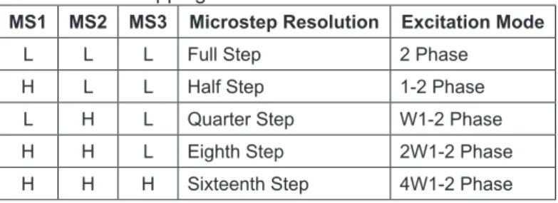
MS1 MS2 MS3 Microstep Resolution Excitation Mode
L L L Full Step 2 Phase
H L L Half Step 1-2 Phase
L H L Quarter Step W1-2 Phase
H H L Eighth Step 2W1-2 Phase
DMOS Microstepping Driver with Translator
And Overcurrent Protection
A4988
Device Operation. The A4988 is a complete microstepping motor driver with a built-in translator for easy operation with minimal control lines. It is designed to operate bipolar stepper motors in full-, half-, quarter-, eighth, and sixteenth-step modes. The currents in each of the two output full-bridges and all of the N-channel DMOS FETs are regulated with fixed off-time PWM (pulse width modulated) control circuitry. At each step, the current for each full-bridge is set by the value of its external current-sense resistor (RS1 and RS2), a reference voltage (VREF), and the output
voltage of its DAC (which in turn is controlled by the output of the translator). At power-on or reset, the translator sets the DACs and the phase current polarity to the initial Home state (shown in Figures 9 through 13), and the current regulator to Mixed Decay Mode for both phases. When a step command signal occurs on the STEP input, the translator automatically sequences the DACs to the next level and current polarity. (See Table 2 for the current-level sequence.) The microstep resolution is set by the combined effect of the MSx inputs, as shown in Table 1. When stepping, if the new output levels of the DACs are lower than their previous output levels, then the decay mode for the active full-bridge is set to Mixed. If the new output levels of the DACs are higher than or equal to their previous levels, then the decay mode for the active full-bridge is set to Slow. This auto- matic current decay selection improves microstepping perfor-mance by reducing the distortion of the current waveform that results from the back EMF of the motor.
Microstep Select (MSx). The microstep resolution is set by
the voltage on logic inputs MSx, as shown in Table 1. The MS1 and MS3 pins have a 100 kΩ pull-down resistance, and the MS2 pin has a 50 kΩ pull-down resistance. When changing the step mode the change does not take effect until the next STEP rising
the home position which is by default common to all step modes.
Mixed Decay Operation. The bridge operates in Mixed decay mode, at power-on and reset, and during normal running according to the ROSC configuration and the step sequence, as shown in Figures 9 through 13. During Mixed decay, when the trip point is reached, the A4988 initially goes into a fast decay mode for 31.25% of the off-time, tOFF . After that, it switches to
Slow decay mode for the remainder of tOFF. A timing diagram for
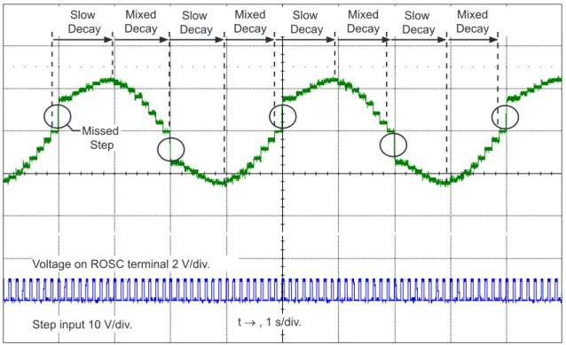
this feature appears on the next page. Typically, mixed decay is only necessary when the current in the winding is going from a higher value to a lower value as determined by the state of the translator. For most loads automatically-selected mixed decay is convenient because it minimizes ripple when the current is rising and prevents missed steps when the current is falling. For some applications where microstepping at very low speeds is necessary, the lack of back EMF in the winding causes the current to increase in the load quickly, resulting in missed steps. This is shown in Figure 2. By pulling the ROSC pin to ground, mixed decay is set to be active 100% of the time, for both rising and falling currents, and prevents missed steps as shown in Figure 3. If this is not an issue, it is recommended that automatically-selected mixed decay be used, because it will produce reduced ripple currents. Refer to the Fixed Off-Time section for details.
Low Current Microstepping. Intended for applications where the minimum on-time prevents the output current from regulating to the programmed current level at low current steps. To prevent this, the device can be set to operate in Mixed decay mode on both rising and falling portions of the current waveform. This feature is implemented by shorting the ROSC pin to ground. In this state, the off-time is internally set to 30 µs. Functional Description
DMOS Microstepping Driver with Translator
And Overcurrent Protection
A4988
8
Allegro MicroSystems, LLC
Figure 2: Missed Steps in Low-Speed Microstepping
Figure 3: Continuous Stepping Using Automatically-Selected Mixed Stepping (ROSC pin grounded) t → , 1 s/div.
Step input 10 V/div.
Mixed Decay No Missed
Steps ILOAD 500 mA/div.
t → , 1 s/div. Step input 10 V/div.
Slow
Decay DecayMixed DecaySlow DecayMixed DecaySlow DecayMixed DecaySlow DecayMixed
Missed Step
DMOS Microstepping Driver with Translator
And Overcurrent Protection
A4988
input sequences the translator and advances the motor one incre- ment. The translator controls the input to the DACs and the direc-tion of current flow in each winding. The size of the increment is determined by the combined state of the MSx inputs.
Direction Input (DIR). This determines the direction of rota-tion of the motor. Changes to this input do not take effect until the next STEP rising edge.
Internal PWM Current Control. Each full-bridge is con-trolled by a fixed off-time PWM current control circuit that limits the load current to a desired value, ITRIP . Initially, a diagonal pair
of source and sink FET outputs are enabled and current flows through the motor winding and the current sense resistor, RSx. When the voltage across RSx equals the DAC output voltage, the current sense comparator resets the PWM latch. The latch then turns off the appropriate source driver and initiates a fixed off time decay mode The maximum value of current limiting is set by the selection of RSx and the voltage at the VREF pin. The transconductance func-tion is approximated by the maximum value of current limiting, ITripMAX (A), which is set by ITripMAX = VREF / ( 8
×
RS)where RS is the resistance of the sense resistor (Ω) and VREF is the input voltage on the REF pin (V).
The DAC output reduces the VREF output to the current sense comparator in precise steps, such that
Itrip = (%ITripMAX / 100)
×
ITripMAX(See Table 2 for %ITripMAX at each step.)
It is critical that the maximum rating (0.5 V) on the SENSE1 and SENSE2 pins is not exceeded. ▪ ROSC through a resistor to ground — off-time is determined by the following formula, the decay mode is automatic Mixed decay for all step modes except full step whic is set to slow decay. tOFF ≈ ROSC ⁄ 825
Where tOFF is in µs.
Blanking. This function blanks the output of the current sense comparators when the outputs are switched by the internal current control circuitry. The comparator outputs are blanked to prevent false overcurrent detection due to reverse recovery currents of the clamp diodes, and switching transients related to the capacitance of the load. The blank time, tBLANK (µs), is approximately
tBLANK ≈ 1 µs
Shorted-Load and Short-to-Ground Protection.
If the motor leads are shorted together, or if one of the leads is shorted to ground, the driver will protect itself by sensing the overcurrent event and disabling the driver that is shorted, protect-ing the device from damage. In the case of a short-to-ground, the device will remain disabled (latched) until the S¯ ¯L¯ ¯E¯ ¯E¯ ¯P¯ input goes high or VDD power is removed. A short-to-ground overcurrent event is shown in Figure 4. When the two outputs are shorted together, the current path is through the sense resistor. After the blanking time (≈1 µs) expires, the sense resistor voltage is exceeding its trip value, due to the overcurrent condition that exists. This causes the driver to go into a fixed off-time cycle. After the fixed off-time expires the driver turns on again and the process repeats. In this condition the driver is completely protected against overcurrent events, but the short is repetitive with a period equal to the fixed off-time of the driver. This condition is shown in Figure 5. During a shorted load event it is normal to observe both a posi-tive and negative current spike as shown in Figure 3, due to the direction change implemented by the Mixed decay feature. This
DMOS Microstepping Driver with Translator
And Overcurrent Protection
A4988
10
Allegro MicroSystems, LLC
VREG(VREG). This internally-generated voltage is used to operate the sink-side FET outputs. The nominal output voltage of the VREG terminal is 7 V. The VREG pin must be decoupled with a 0.22 µF ceramic capacitor to ground. VREG is internally monitored. In the case of a fault condition, the FET outputs of the A4988 are disabled.
Capacitor values should be Class 2 dielectric ±15% maximum, or tolerance R, according to EIA (Electronic Industries Alliance) specifications.
Enable Input (¯E¯ ¯N¯ ¯A¯ ¯B¯ ¯L¯ ¯E¯ ). This input turns on or off all of the FET outputs. When set to a logic high, the outputs are disabled. When set to a logic low, the internal control enables the outputs as required. The translator inputs STEP, DIR, and MSx, as well as the internal sequencing logic, all remain active, independent of the ¯E¯ ¯N¯ ¯A¯ ¯B¯ ¯L¯ ¯E¯ input state. Shutdown. In the event of a fault, overtemperature (excess TJ) or an undervoltage (on VCP), the FET outputs of the A4988 are disabled until the fault condition is removed. At power-on, the UVLO (undervoltage lockout) circuit disables the FET outputs and resets the translator to the Home state.
Sleep Mode ( ¯S¯ ¯L¯ ¯E¯ ¯E¯ ¯P¯ ). To minimize power consumption
when the motor is not in use, this input disables much of the internal circuitry including the output FETs, current regulator, and charge pump. A logic low on the S¯ ¯L¯ ¯E¯ ¯E¯ ¯P¯ pin puts the A4988 into Sleep mode. A logic high allows normal operation, as well as start-up (at which time the A4988 drives the motor to the Home microstep position). When emerging from Sleep mode, in order to allow the charge pump to stabilize, provide a delay of 1 ms before issuing a Step command.
Mixed Decay Operation. The bridge operates in Mixed Decay mode, depending on the step sequence, as shown in Fig-ures 9 through 13. As the trip point is reached, the A4988 initially goes into a fast decay mode for 31.25% of the off-time, tOFF. After that, it switches to Slow Decay mode for the remainder of tOFF. A timing diagram for this feature appears in Figure 7.
Synchronous Rectification. When a PWM-off cycle is
triggered by an internal fixed-off time cycle, load current recircu-lates according to the decay mode selected by the control logic. This synchronous rectification feature turns on the appropriate FETs during current decay, and effectively shorts out the body diodes with the low FET RDS(ON). This reduces power dissipation
significantly, and can eliminate the need for external Schottky diodes in many applications. Synchronous rectification turns off when the load current approaches zero (0 A), preventing reversal of the load current. t → Fixed off-time 5 A / div. t → 5 A / div.
Figure 4: Short-to-Ground Event
Figure 5. Shorted Load (OUTxA → OUTxB) in Slow Decay Mode
Figure 6: Shorted Load (OUTxA → OUTxB) in Mixed Decay Mode
Fixed off-time
Fast decay portion (direction change)
t → 5 A / div.
Fault latched
DMOS Microstepping Driver with Translator
And Overcurrent Protection
A4988
VSTEP IOUT IOUT t See Enlargement A Enlargement A tSD tFD toff Slow Decay Mixed Decay Fast Decay IPEAK 70.71 –70.71 0 100.00 –100.00DMOS Microstepping Driver with Translator
And Overcurrent Protection
A4988
12 Allegro MicroSystems, LLC Application Layout Layout. The printed circuit board should use a heavy ground-plane. For optimum electrical and thermal performance, the A4988 must be soldered directly onto the board. Pins 3 and 18 are internally fused, which provides a path for enhanced thermal dissipation. Theses pins should be soldered directly to an exposed surface on the PCB that connects to thermal vias are used to transfer heat to other layers of the PCB. In order to minimize the effects of ground bounce and offset issues, it is important to have a low impedance single-point ground, known as a star ground, located very close to the device. By making the connection between the pad and the ground plane directly under the A4988, that area becomes an ideal location for a star ground point. A low impedance ground will prevent ground bounce during high current operation and ensure that the supply voltage remains stable at the input terminal. The two input capacitors should be placed in parallel, and as close to the device supply pins as possible. The ceramic capaci-tor (CIN1) should be closer to the pins than the bulk capacitor (CIN2). This is necessary because the ceramic capacitor will be responsible for delivering the high frequency current components. The sense resistors, RSx , should have a very low impedance path to ground, because they must carry a large current while supporting very accurate voltage measurements by the current sense comparators. Long ground traces will cause additional voltage drops, adversely affecting the ability of the comparators to accurately measure the current in the windings. The SENSEx pins have very short traces to the RSx resistors and very thick, low impedance traces directly to the star ground underneath the device. If possible, there should be no other components on the sense circuits. VBB VDD 1 PAD A4988 C3 C6 R1 R2 R3 C1 C8 C2 C9 C7 RS2 RS1 R6 C4 OUT1B NC DIR REF STEP VDD OUT2B ENABLE CP1 CP2 VCP NCVREG MS1 MS2 MS3 RESET ROSC SLEEP
VBB2 SENSE2 OUT2A NC OUT1A SENSE1 VBB1 GND GND PCB Thermal Vias Trace (2 oz.) Signal (1 oz.) Ground (1 oz.) Thermal (2 oz.) Solder A4988
DMOS Microstepping Driver with Translator
And Overcurrent Protection
A4988
VCP GND CP2 GND CP1 VBB 8 V GND VDD GND GND 8 V GND GND 8 V VBB VREG 10 V GND DMOS Parasitic SENSE VREG GND VBB 40 V GND VBB OUT DMOS Parasitic DMOS Parasitic GND PGND GND MS1 MS2 MS3 DIR VREF ROSC SLEEPDMOS Microstepping Driver with Translator
And Overcurrent Protection
A4988
14
Allegro MicroSystems, LLC
Figure 10: Decay Modes for Half-Step Increments Figure 9: Decay Mode for Full-Step Increments
*With ROSC pin tied to GND
Mixed* Phase 2 IOUT2A Direction = H (%) Phase 1 IOUT1A Direction = H (%) STEP
Home Microstep Position Home Microstep Position
100.00 70.71 –70.71 0.00 –100.00 100.00 70.71 –70.71 0.00 –100.00 Slow RESET
*With ROSC pin tied to GND
Home Microstep Position Home Microstep Position
100.00 70.71 –70.71 0.00 –100.00 100.00 70.71 –70.71 0.00 –100.00 Phase 2 IOUT2B Direction = H (%) Phase 1 IOUT1A Direction = H (%) STEP Slow Mixed Mixed* Mixed* Slow Mixed Slow Mixed Mixed Slow Mixed Slow Mixed Slow Slow 0.00 100.00 92.39 70.71 38.27 –38.27 –70.71 –92.39 –100.00 0.00 100.00 92.39 70.71 38.27 –38.27 –70.71 –92.39 –100.00 Phase 2 IOUT2B Direction = H (%) Phase 1 IOUT1A Direction = H (%)
Home Microstep Position
Slow Mixed Slow Mixed Slow
Slow Mixed Slow Mixed
Mixed STEP
Slow
Mixed*
Mixed*
*With ROSC pin tied to GND
Figure 11: Decay Modes for Quarter-Step Increments
DIR= H
DMOS Microstepping Driver with Translator
And Overcurrent Protection
A4988
Figure 12: Decay Modes for Eighth-Step Increments
Mixed Mixed
Slow Slow
Mixed Slow Mixed Slow
0.00 100.00 92.39 70.71 55.56 –55.56 83.15 –83.15 38.27 19.51 –19.51 –38.27 –70.71 –92.39 –100.00 0.00 100.00 92.39 70.71 55.56 –55.56 83.15 –83.15 38.27 19.51 –19.51 –38.27 –70.71 –92.39 –100.00 Phase 2 IOUT2B Direction = H (%) Phase 1 IOUT1A Direction = H (%)
Home Microstep Position
STEP
Mixed*
Mixed*
*With ROSC pin tied to GND
DMOS Microstepping Driver with Translator
And Overcurrent Protection
A4988
16
Allegro MicroSystems, LLC
Figure 13: Decay Modes for Sixteenth-Step Increments
Mixed Slow Mixed* Mixed* Mixed Slow Mixed Slow Slow Slow 100.00 95.69 88.19 83.15 –83.15 77.30 70.71 63.44 55.56 47.14 38.27 29.03 19.51 9.8 0.00 –100.00–95.69 –88.19 –77.30 –70.71 –63.44 –55.56 –47.14 –38.27 –29.03 –19.51 –9.8 100.00 95.69 88.19 83.15 –83.15 77.30 70.71 63.44 55.56 47.14 38.27 29.03 19.51 9.8 0.00 –100.00–95.69 –88.19 –77.30 –70.71 –63.44 –55.56 –47.14 –38.27 –29.03 –19.51 –9.8 Phase 2 IOUT2B Direction = H (%) Phase 1 IOUT1A Direction = H (%)
Home Microstep Position
Mixed
*With ROSC pin tied to GND
STEP
DMOS Microstepping Driver with Translator
And Overcurrent Protection
A4988
Table 2: Step Sequencing Settings
Home microstep position at Step Angle 45º; DIR = H Full Step # Half Step # 1/4 Step # 1/8 Step # 1/16 Step # Phase 1 Current [% ItripMax] (%) Phase 2 Current [% ItripMax] (%) Step Angle (º) Full Step # Half Step # 1/4 Step # 1/8 Step # 1/16 Step # Phase 1 Current [% ItripMax] (%) Phase 2 Current [% ItripMax] (%) Step Angle (º) 1 1 1 1 100.00 0.00 0.0 5 9 17 33 –100.00 0.00 180.0 2 99.52 9.80 5.6 34 –99.52 –9.80 185.6 2 3 98.08 19.51 11.3 18 35 –98.08 –19.51 191.3 4 95.69 29.03 16.9 36 –95.69 –29.03 196.9 2 3 5 92.39 38.27 22.5 10 19 37 –92.39 –38.27 202.5 6 88.19 47.14 28.1 38 –88.19 –47.14 208.1 4 7 83.15 55.56 33.8 20 39 –83.15 –55.56 213.8 8 77.30 63.44 39.4 40 –77.30 –63.44 219.4 1 2 3 5 9 70.71 70.71 45.0 3 6 11 21 41 –70.71 –70.71 225.0 10 63.44 77.30 50.6 42 –63.44 –77.30 230.6 6 11 55.56 83.15 56.3 22 43 –55.56 –83.15 236.3 12 47.14 88.19 61.9 44 –47.14 –88.19 241.9 4 7 13 38.27 92.39 67.5 12 23 45 –38.27 –92.39 247.5 14 29.03 95.69 73.1 46 –29.03 –95.69 253.1 8 15 19.51 98.08 78.8 24 47 –19.51 –98.08 258.8 16 9.80 99.52 84.4 48 –9.80 –99.52 264.4 3 5 9 17 0.00 100.00 90.0 7 13 25 49 0.00 –100.00 270.0 18 –9.80 99.52 95.6 50 9.80 –99.52 275.6 10 19 –19.51 98.08 101.3 26 51 19.51 –98.08 281.3 20 –29.03 95.69 106.9 52 29.03 –95.69 286.9 6 11 21 –38.27 92.39 112.5 14 27 53 38.27 –92.39 292.5 22 –47.14 88.19 118.1 54 47.14 –88.19 298.1 12 23 –55.56 83.15 123.8 28 55 55.56 –83.15 303.8 24 –63.44 77.30 129.4 56 63.44 –77.30 309.4 2 4 7 13 25 –70.71 70.71 135.0 4 8 15 29 57 70.71 –70.71 315.0 26 –77.30 63.44 140.6 58 77.30 –63.44 320.6
![Figur 2.1. RGB-modellen [13]](https://thumb-eu.123doks.com/thumbv2/5dokorg/4588485.117791/19.892.330.562.202.469/figur-rgb-modellen.webp)