This paper was published in Tribology International Volume 60 (2013), 136-139 Online version http://dx.doi.org/10.1016/j.triboint.2012.11.013
Pin-on-disc study of the effects of railway friction modifiers on airborne wear particles
from wheel–rail contacts
Saeed Abbasi, Ulf Olofsson, Yi Zhu, Ulf Sellgren KTH Machine Design, SE 10044, Stockholm, Sweden Corresponding author’s email address: sabbasi@md.kth.se
ABSTRACT
Knowledge of wheel–rail interaction is crucial to wheel and rail maintenance. In this interaction, some of the worn-off material is transformed into airborne particles. Although such wear is well understood, few studies treat the particles generated. We investigated friction modifiers' effects on airborne particles characteristics generated in wheel-rail contacts in laboratory conditions. Pin-on-disc machine testing with a round-head pin loaded by a dead weight load 40 N simulated maximum contact pressure over 550 MPa. Airborne particle characteristics were investigated in dry contacts and in ones lubricated with biodegradable rail grease and water- and oil-based friction modifiers. The number of particles declined with the grease; the number of ultrafine particles increased with the water-based friction modifier, mainly due to water vaporization.
Keywords: Airborne particles, Lubricant, Railway, Wear
1. Introduction
Wheel–rail contact behaviour is a multifaceted issue of interest in both theoretical and applied research, particularly in tribology. The main tribological objective in this area is to optimize the wheel–rail contact by facilitating proper frictional behaviour and alleviating wear and noise.
According to a recent comprehensive study of wheel–rail contact problems [1], friction modifiers can successfully be used to achieve these objectives. Tomeoka et al. [2] reported the positive effects of using various friction modifiers to control the coefficient of friction. The successful application of friction modifiers is also described by Eadie et al. [3].
However, no published research has described how friction modifiers affect the generation of airborne particles in the wheel–rail contact. This issue is crucial, since the wheel–rail contact is an open system. The high contact pressure in the wheel–rail contact induces high temperatures [1], which affect both the number and characteristics of the airborne particles generated. According to a recent review [4], airborne particles generated by rail traffic could cause human health problems. In addition, airborne particles emitted from the wheel–rail contact comprise a considerable proportion of the total number and mass of particles originating from rail traffic [4,5].
The main purpose of this study is to investigate the effects of friction modifiers on the number and size of airborne particles generated in the wheel–rail contact under controlled laboratory conditions.
This paper was published in Tribology International Volume 60 (2013), 136-139 Online version http://dx.doi.org/10.1016/j.triboint.2012.11.013
2. Experimental set-up
2.1 Particle-measurement devices
In this study, three types of particle-measurement instruments were used to measure the airborne particle number concentration (PNC), i.e., the number of particles per litre of air, in various particle diameter (dp) size intervals. The main instrument used was a model 1.109 aerosol spectrometer (Grimm Aerosol Technik, Ainring, Germany). This device measured the PNC in 31 size intervals ranging from 250 nm to 32 µm in diameter. It could be set up to measure fine particles (100 nm < dp ≤ 1 µm) over 250 nm in diameter and coarse particles (dp > 1 µm) up to 32 µm in diameter. The second device used was a P-TRAK Ultrafine Particle Counter 8525 (TSI, Shoreview, MN, USA). The P-TRAK device is a condensation nuclei counter that measures the PNC in the 0.02–1-µm-diameter size interval, which includes the fine region and, mainly, the ultrafine region (dp < 100 nm). We used this device to test the cleanliness of the chamber and the incoming air before starting each test. The third instrument was a scanning mobility particle sizer (SMPS) able to measure fine and ultrafine particle concentrations in 110 size intervals ranging from a particle diameter of 10 nm to 540 nm. The 110 factory-designated intervals facilitated the measurement of particle concentrations and helped us investigate the fine and ultrafine particles (dp < 250 nm) undetectable using the aerosol spectrometer. The SMPS combined an electrostatic classifier (model 3071; TSI) with a particle counter (model CPC 3010; TSI). The technical specifications and set-ups of these measuring devices were similar to those used by Sundh and Olofsson [6] and Abbasi et al. [7,8].
2.2 Test equipment
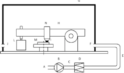
The laboratory tests were performed using a pin-on-disc machine equipped with a horizontal rotating disc and a dead-weight-loaded pin. The pin-on-disc machine was operated in a sealed box to ensure the cleanliness of the incoming air (see Fig. 1). This set-up was previously used by Abbasi et al. [7,8].
Fig. 1. Schematic of the test equipment. A: room air; B: fan; C: flow rate measurement; D: filter; E: flexible tube; F: clean air inlet, measurement point; G: sealed box; H: pin-on-disc machine; I: pin sample; J: air outlet, measurement points; L: dead weight; M: rotating disc sample, and N: air inside chamber.
This paper was published in Tribology International Volume 60 (2013), 136-139 Online version http://dx.doi.org/10.1016/j.triboint.2012.11.013
2.3 Material preparation, lubricants, and test plan
The discs and pins were made of a used R7 wheel and a piece of used UIC 60, 1100 rail with hardnesses of 270 and 280 HV, respectively. The 110-mm-diameter discs and the 100-mm-high round-head pins (R = 25 mm) were cut from the materials using a water jet cutting machine. The quality of the machined surface, i.e., the Ra value, was 0.3–0.6 µm for both materials. Before testing, the disc specimens were cleaned ultrasonically for 20 minutes with both heptane and methanol.
The load applied on the round-head pin was 40 N, representing a Hertzian maximum contact pressure of 550 MPa in the pin and disc contact, and the sliding velocity was 0.l m s–1. This relatively low sliding velocity represents a typical sliding velocity encountered in a wheel–rail contact interface under normal creep conditions [9].
We investigated the characteristics of airborne particles produced in dry and lubricated contacts. Two types of friction modifiers, one vegetable oil-based (“type A”) and the other water-based (“type B”), were used. A rail grease was also used for purposes of comparison. The technical specifications of the friction modifiers and rail grease are presented in Table 1.
The biodegradable rail grease was applied to the contact zone with a syringe, originally manufactured for applying glue, powered by compressed air; the lubrication protocol, which was controlled by computer software, was initially set to apply 0.02 g of lubricant for every 8 m of sliding. Types A and B friction modifiers were applied using a fine brush so as to cover the disc surface with the lubricant.
The whole system, including the pin-on-disc machine, was tested by starting all components simultaneously without any contact between the pin and disc. The PNC measured in the outlet reached zero after 5–10 min, depending on earlier activities in the room and in the box; wear testing started only after the PNC had reached zero. During the tests, the temperature was 20 ± 2ºC and the relative humidity was 40 ± 5%. Two individual tests were run for each material combination.
3. Results
Figs. 2 and 3 show the PNC test results for the three friction modifiers under controlled laboratory conditions. In all tests, the static load applied on the round-head pin (R = 25 mm) was 40 N and the sliding velocity was 0.1 m s–1.
In Fig. 2, the left vertical axes indicate the measured number of airborne particles per litre of air (PNC) for particles in the size range 0.25 µm < dp < 32 µm (shown by a solid line) and the right vertical axes indicate
Friction modifier/Grease Density (kg m–³) Lubricant Viscosity (Pa.s) at 25ºC
Main application
Type A 1150 Vegetable oil-based N.A. Reducing wheel
squalling
Type B 1350 Water-based N.A. Increasing friction
coefficient Biodegradable rail grease 1000 Vegetable oil 0.5 Reducing wear in
high rails Table 1. The technical specifications of the friction modifiers and rail grease in this study.
This paper was published in Tribology International Volume 60 (2013), 136-139 Online version http://dx.doi.org/10.1016/j.triboint.2012.11.013
the PNC for particles in the size range 1 µm < dp < 32 µm (shown by a dotted line). These results were obtained using a Grimm aerosol spectrometer.
This paper was published in Tribology International Volume 60 (2013), 136-139 Online version http://dx.doi.org/10.1016/j.triboint.2012.11.013
Fig. 2 (a–d). Typical particle count as a function of time (obtained using a Grimm aerosol spectrometer) for a dry wheel– rail contact (a), a wheel–rail contact lubricated with friction modifier type A (b), a wheel–rail contact lubricated with friction modifier type B (c), and a wheel–rail contact lubricated with a biodegradable rail grease (d). The solid line (left axis) shows the PNC for the 0.25 µm < dp < 32 µm size interval and the dotted line (right axis) for the 1 µm < dp < 32 µm size interval.
The PNCs remained almost constant over time in the dry contact without any lubricant (see Fig. 2a), and were 58 and 11 particles L–1 s–1 in the 0.25 µm < dp < 32 µm and 1 µm < dp < 32 µm size intervals, respectively. In the lubricated case using friction modifier type A, the PNC fluctuated over time, although the PNC trend indicates a general increase over time (see Fig. 2b); the average PNCs in the 0.25 µm < dp < 32 µm and 1 µm < dp < 32 µm size intervals were over 70% lower than for the dry contact. With friction modifier type B, the PNC remained almost constant over time. As shown in Fig. 2c, the average PNCs in the 0.25 µm < dp < 32 µm and 1 µm < dp < 32 µm size intervals were 30% lower than for the dry contact. When the contact was lubricated with the biodegradable rail grease (see Fig. 2d), the PNC fluctuated over time, although the PNC trend indicates a general increase over time. Here, the average PNCs in the 0.25 µm < dp < 32 µm and 0.25 µm < dp < 32 µm size intervals were 85% and 95% lower than for the dry contact.
Fig. 3 presents the particle size distribution of submicron-sized particles. The vertical axes indicate the logarithmic PNC (10 nm < dp < 540 nm) mL–1 and the horizontal axes indicate the particle diameter in nm, measured using an SMPS. The particle size distribution was recorded every 5.5 min.
This paper was published in Tribology International Volume 60 (2013), 136-139 Online version http://dx.doi.org/10.1016/j.triboint.2012.11.013
Fig. 3 (a–d). Typical particle count of the size distribution of particles in the 10 nm < dp < 540 nm size interval recorded using an SMPS for a dry wheel–rail contact (a), a wheel–rail contact lubricated with friction modifier type A (b), a wheel– rail contact lubricated with friction modifier type B (c), and a wheel–rail contact lubricated with a biodegradable rail grease (d).
According to these results, the logarithmic PNC for submicron-sized particles when using friction modifier type A (Fig. 3b) and biodegradable grease (Fig. 3d) decreased drastically, being considerably lower than for a dry contact (Fig. 3a). However, the use of friction modifier type B greatly increased the PNC. According to Fig 3c, the logarithmic PNC when using friction modifier type B was hundreds of times greater than that for a dry contact, as shown in Fig. 3a.
4. Discussion
Figs. 2–3 show that wear occurs in the wheel–rail interface, even in a low-speed sliding contact (i.e., 0.1 m s–1). The wear process generates airborne particles in the coarse, fine, and ultrafine size regions in all cases, though the number of generated particles and the relative particle size distribution are highly dependent on the type of lubricant applied in the contact.
According to the results shown in Figs. 2c and d, the number of coarse particles was effectively reduced when rail grease or a friction modifier was used. The greatest effectiveness was recorded with the use of biodegradable rail grease, which resulted in a 95% reduction in the concentration of coarse particles. Friction modifiers also reduced the particle concentration, by approximately 70% for the oil-based and 30% for the water-based friction modifier.
This effective reduction in the number of coarse particles can be explained by a shift from dry contact to boundary lubrication conditions. Boundary lubrication reduces the adhesive force between two surfaces in contact and can thus reduce wear. In addition, some particles are trapped in the lubricant and do not become airborne. The number of ultrafine particles decreased when biodegradable rail grease or oil-based friction modifier was used. In contrast, the concentration of ultrafine particles increased drastically when water-based lubricant was used; this effect can be explained by frictional heating in the wheel–rail contact interface.
According to Knothe and Liebelt [10], the contact temperature is determined by the rolling speed, creep, coefficient of friction, pressure distribution, and axle load, as well as by the wheel and rail material properties. In the studied case, we have no actual creep, but a pure sliding motion that represents typical creep conditions. The temperature profile change can be estimated from the particular sliding velocity and contact conditions, as presented in Fig. 4.
This paper was published in Tribology International Volume 60 (2013), 136-139 Online version http://dx.doi.org/10.1016/j.triboint.2012.11.013
Fig. 4. The temperature profile estimation for these experiments, based on the Knothe and Liebelt model [10]. It must be noted that the real temperature would be higher if we took account of the bulk temperature of the pin and disc. Before running the test, the bulk temperature of the pin and disc equals the ambient temperature, i.e., room temperature, but during the test, the bulk temperature increases because of frictional heating. Besides, the flash temperature would be higher at the asperity level, where the contact pressure is significantly higher than the mean nominal contact pressure. A temperature near the boiling point of water (100ºC) would vaporize any water present and increase the number ultrafine particles generated.
Doubtless, metal particles from the pin and disc, oil, and additives of grease and friction modifier all contribute to generating ultrafine particles; further investigation is merited to determine the contribution of these sources to the total generated ultrafine particles. However, their contribution can be neglected in view of the high amount of ultrafine particles recorded when we used water-based friction modifier, and because the size distribution of the recorded ultrafine particles was akin to that of water vapour droplets produced in the boiling process of water [11]. The size distribution of water vapour droplets produced in the water boiling process follows an exponential pattern, increasing drastically in small size intervals.
The risk of water vaporization is a limitation of water-based friction modifiers. As explained, high contact pressures, sliding velocities, and ambient temperatures all increase this risk. This limitation must be taken into account when using water-based friction modifiers in any open lubrication systems, particularly wheel– rail contacts. In addition, the consequences of water-based lubricants freezing at temperatures below the freezing point are also crucial and should be taken into account as further limitations of such friction modifiers. This issue is beyond the scope of this paper and calls for further investigation.
For example, when a rail vehicle is running around a curve, especially a tight curve, both the sliding velocity and the pressure are so high that they can cause flash temperatures higher than 500ºC [12,13]. This temperature will be several times higher in a flange contact [12,13]. As a result, the flash temperature in the flange contact in a high rail or the contact for locomotives can easily exceed 100ºC, vaporizing the water in the friction modifier and increasing the replacement rate needed to keep the same functionality.
This paper was published in Tribology International Volume 60 (2013), 136-139 Online version http://dx.doi.org/10.1016/j.triboint.2012.11.013
5. Conclusions
The following general conclusions can be drawn from the test results:
1. Friction modifiers can be used on rails or wheels to reduce the number of coarse particles released to the ambient air.
2. The use of water-based lubricants in the wheel–rail contact can generate ultrafine particles.
3. In situations of potentially high contact temperatures (e.g., high rails, tight curves, high axle loads, and hot weather) in railway traffic, water-based lubricants should only be used after considering the high replacement rate needed due to vaporization.
Acknowledgments
This work represents part of the regular research activities of the Railway Group, KTH Royal Institute of Technology, Stockholm, Sweden.
References
[1] Lewis R, Olofsson U. Wheel–rail interface handbook, 1st ed. Cambridge, CRC Press, UK, 2009.
[2] Tomeoka M, Kabea N, Tanimoto M, Miyauchi E, Nakata M. Friction control between wheel and rail by means of on-board lubrication. Wear 2002;253:124–29.
[3] Eadie DT, Elvidge D, Oldknow K, Stock R, Pointner P, Kalousek J, Klauser P. The effects of top of rail friction modifier on wear and rolling contact fatigue: full-scale rail–wheel test rig evaluation, analysis and modelling, Wear 2008;256:1222–30.
[4] Abbasi S, Jansson A, Olofsson U, Sellgren U. Particle emissions from rail traffic: a literature review. Critical Reviews in Environmental Science and Technology, In press.
[5] Abbasi S, Jansson A, Olander L, Olofsson U, Sellgren U, Larsson C. A field test study of airborne wear particles from a running regional train. IMechE Part F: Journal of Rail and Rapid Transit 2012;226:95– 109.
[6] Sundh J, Olofsson U. Relating contact temperature and wear transitions in a wheel–rail contact. Wear 2011;271:78–85.
[7] Abbasi S, Jansson A, Olander L, Olofsson U, Sellgren U. A pin-on-disc study of the rate of airborne wear particle emissions from railway braking materials. Wear 2012;284–85:18–29.
[8] Abbasi S, Wahlström J, Olander L, Larsson C, Olofsson U, Sellgren U. A study of airborne wear particles generated from organic railway brake pads and brake discs. Wear 2011;273:93–9.
[9] Olofsson, U. and T. Telliskivi, Wear, plastic deformation and friction of two rail steels: a full-scale test and a laboratory study. Wear 2003;254:80–93.
[10] Knothe K, Liebelt S. Determination of temperatures for sliding contact with applications for wheel– rail systems. Wear 1995;189:91–9.
[11] See SW, Balasubramaniana R. Physical characteristics of ultrafine particles emitted from different gas cooking methods. Aerosol and Air Quality Research 2006;6(1):82–92.
[12] Fischer FD, Daves W, Werner EA. On the temperature in the wheel–rail rolling contact. Fatigue and Fracture of Engineering Materials and Structures 2003;26:999–1006.
[13] Spiryagin M, Loo K, Yoo H. Numerical calculation of temperature in the wheel–rail flange contact and implications for lubricant choice. Wear 2004;268:287–93.

![Fig. 4. The temperature profile estimation for these experiments, based on the Knothe and Liebelt model [10]](https://thumb-eu.123doks.com/thumbv2/5dokorg/4259106.94154/7.918.246.670.71.424/temperature-profile-estimation-experiments-based-knothe-liebelt-model.webp)
