Bulletin _ _ _ _ _ _
j
CoLORADO AGRICULTURAL CoLLEGE CoLORADO ExPERIMENT STATION
By Ralph L. Parsha~, ~3enio_r Irrigation Engineer
,.,..---...
/ ' '
!/'Prepared under the direction of W. ""!. ~,~rcie.ug;hlin, ~hief,
Jivision of Irrigation, United States Depart~ent of Agriculture, 3ureau of .Agricultural :f~ngineerine;, f). T'". ~·-:ccror;r, Chief.
Based on data gathered under cooperative agree'y:ent between Bureau of Agricultural '~ngir;.eering, Urited States DepRrtnent of Agriculttu·e, and colorado Rxpcrir::.ent 3tatioP .
Ll:..RGE PARSF.J.l.IL I.'JEA.SURING FLUl'iESY ~ tal:ph L. Parshall
'ro L'leet the practical requirements of the ·rt;easurernent of large streams of water up to 2,000 second-feet or more, there has been developed the Parshall measurinr; flume, the design of which i·s based on the s~udy of and experience with small flumes, both ·in the field and labors tor:'.
Y
Venturi li'lurr:e. 3111 etin 265, Colorado 3x:p erirr.ent ~ tP tion. Improved Venturi r'lU"''e. -iulletin 336, Colorado :r.:x:perir:ent Station. The ·.~_)arshall measuring flume forr,erly known as The Improved Venturi ~lume.
Because of the i!npracticability of the ordinary rating flQme, especially in the Arkansas .. ialley of ColoTado, an excellent opportUl.1i ty -vns presented for perfectine a measuring device which could successfully meet the ad-verse conditions experienced with the use of the rating flume in this val-ley. From the standpoint of administration of the river and reservoir waters in regard to the several appropriators along the river, it is of prime importance that the State Engineer and his official staff should know, within reasonable lini ts, tho rate of flow being diverted f:rom the river into the various canals according to the terms of their priority decrees.
The Arkansas River in Colorado is well known as a stream which carries a heavy burden of sand and silt
..flee ... r faun€!, fter a number
flume, used as a measuring device 'A~ wholly inadequate and unreliable in its operation. _n some cases the sQnd and silt carried into the canals
2
-caused a considerable change in the stage or depth of r~ter in the chan-nel, due to the scouring out or filling in of the bed load moving a long
the bottom. As an extreme case, it has been observed on some of the canals of this valley that for the same depth or gage height, the rate of flow might vary nearly 100 percent, due to the shift of sand and silt de-posit in the channel duriP_.e a 1Jlodera.tely short period of time. ·-:lor the
'),s-ilolbrook Canal there has been as much as feet of sand deposited on the floor of the old rating flume, which was 32 feet wide and ? feet deep. ~onsiderable attention on the part of the state hydrograpnic force was
ne-l"y'{l.l~
cessary in the flow fi'o:-': the river, and preparing a rating teble to govern the operation of the several headgates along the stream. ne -cause of the shifting of the discharge curves, it was found practically impossible to determine accurately the rate of flow in ma.ny of the canals. 'l'his condition vas unsatisfactory, both to the user and water official.
li'rom the standpoint of operation of the canal, the superintendent and his assistants : certaiL arra J:6eraents for the deli very of the water to the farmer in the setting of headgates according to the arrount flowing
in the v~rious sections of the canal. It vms not ::t~ after sue~ C$ settings had been made, to Dzve the official hydrographer check the flow
and find the actual discharge either too great or too small, thus requir-ing a change in the amount of discharge to agree Tiit1 lawful or rig~tful diversion according to priority jecree-r Such ch require i mediate resetting and adjustment
o1~headgat~s
along the canal, and in the case of lessening the rate of flow1 caus dissatisfaction on the :part of the users, particularly at ti es of eztreme necessit, Vlhen there was a shortage of v.ater. In s cne instances, temporary checks in the channel some distance dm-mstream from the ratin,_ flume were necessary
3-to raise the water ernugh to accommodate adjacent high lands by divers~on thr a headgate. ~is check usually raised the water surface. in the rating flume, thus shifti~~ the rating curve to agree with a temporary con-dition. ·_;:ne operation of a water-stage recording instrument (as required by I itate law) in connection with the n'ting flume
was~
. in some instances, somev1hat unsatisfactory because of "the de:posi t accumulating in the float vrell.:.~1
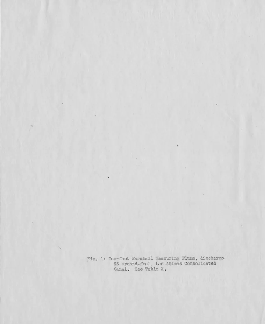
he first atten~t to ir.tprove conditions of measurement in the Arkan-sas :2i ver Valley was in the installation of a 10-f oot Pars he.ll measuTinr; flume on :the Las .Animas Gons olidated Ditch near las .Anims
~ig
.
1~
':.'his experL. .... ental structure was built of untreated common fir lumber in Ivarch, 1926, and has been in constant use since that time. 1~e condition to be met there v,ras in correcting an unstable relation between discharge and gagebackwater height in the old ro. till[s flume, and also to provide aga :i.nst the/\ effect of a check located downstream. After the new device was in operation, the discharge v1as found to be independent of backwater caused by the check, and sand or silt had no effect u:pon the indicated rate of discharge. ?.he ordinary flow thr this flume is 50 second-feet, and numerous check measurements by means of the current meter indicate that the rate of
dis-charge from about 12 second-feet to near J.y 130 second-feet agrees ui thin practical limits with the coiiJ.})uted dischar~e, based on the general law of flow
thr~ l~ge
sizJ structures. (See Table-~)
• T'ive :rears' exper-ience with this improved method of measurinp i11dicates that it has been successful, with the minor exception of requiring the cleaninr of the float well occasionally. r;he o:peration of this first flume., whichas this problemA met, that other canal com:panie~ becDJTie interested e:::ough
to solicit assistance in solving their measuring problems.
1
2he next step in the development of the large Parshn.ll measuri g
flume was the building of a 20-foot reinforced con crete flume in L1e
Hol-brook canal near Hocky Ford ~ig • 2 • This canal, like many others in the
valley, was subject to erratic variation in the relation of discharge to
gage height for the old rating flume. The new flume, built in November,
1927~ with a capacity of about 1,000 second-feet, has met successfully the
trying conditions of Cariation in discharge, due to filling in and soour
-4
-ing out of the channel, either upstream or downstream from the new· structure. rlhe Fort Iqon Canal, (ila;ing a
C~ll_acit
·~of
ab~ut
1,800'"secon~
-
feet
,
.~Mli~•liliiP
.
the largest iiTigation canal inColorad~~
· · · . - ,.-~~J~.~~~ii~~·~~he~~~
was subject to unstable flow conditions. Since the distribution of water
in the river depended largely upon the draft of this canal, the accuracy of
discharge measurements was relativezy important and required the al111ost
constant attention of one hydr grapher in gaging the flow. :ne success aT
the 2.0-foot flume on the Holbrook Canal is believed largely res :pons ible I
for the fi~ql approva~by the §ort Lyon Canal Company and 8tate water offi
-cials. of the installation, near the headworks, of a 40-foot rei:r~forced
con-crete Parshall measuring flume, the largest sti'l.lCture of this t '"pe so far
construc.ted Figs. 3 and 4:) This structure, having a capacity of more than
2,000 second-feet., was built in :Jecer.ber, 1928., and since then numerous
current-meter check moosurements have been made of flows ranging from about
130 second-feet to 1,460 second-feet. These neasm--ements have been found
[l 1(
ie~·
0>ee
built.~ A maximum discharge of 1,800 second-feet has been passed thr
5
-this large structure. This flume has proved very satisfactory in its opera -tion, and has solved a very perplexing measuring problem as well as alleviat -ing the tension and so:aetimes strained relations
appropriators along the river.
':he successful operation of these large flumes on several canals has been sufficient to show the practicability and reliability of this new
device, and now in the .~kansas Valley virtually every diversion from the river, between Pueblo and the I\ansas state line, has beer- provided with a suit -able and adequate -arshall measuring flQme. 'J.:11ese flumes are being used of -ficially ir- tee measurement of v~ter diverted from streams in various irri
-~ ,..a ted 1 i ?1
i ' in Colorado and other .-!estern States •
~
.1\
Inl915~experiments
were made by V.1
:
.
Cone at the hydrauliclaboratory of the Colorado 3xperiment Station on a device known
~ on the Venturi flume•
o/
as the Yentu.ri .flume •.
V
later exper :i.rrt.entsl\were made by Carl Rohwer and the writer in 1920 at both the hydraulic laboratory at ]'art Collins, and at theVJournal of Agricultural Research, Vol. IX, No. 4, p. 115, .t.~.:pril, 1917.
·r'The Venturi ~,'lume, Eulletin 265, Colorado :::Jxpt. station, 1921.
Bellvue laboratory on the Cache la ?oudre ~ iver, (Bigh't2 mil'es west of Fort Col -lins. ~e investigations covered in these studies were for a device having converginf entrance and diverging outlet sections, joined with an intermediate throat. 171he walls were either vertical or inclined outward, and the floor
in the design of t" ,is device, v1here the angle of conver ence and diverpence was changed, the length of these sections altered~ and in the throat the floor
•
•6
-was inclined do\T.Uward~ forrr.dng & fixed crest and control at the junction of the converging section and the throat. ~he walls were vertical and the floor of the converging section level, while the floor of the diverging·sec -tion inclined upward to the lower end of the structure. ·· ' This device has
The Improved Venturi ?lume, Bulletin 336, UoloTado Ex:pt.
Station, 1928.
since been named the 1:'1arshall T.~easuring l?lune, -';he design of ·which is si, i-lar to the d. evice just described~ but -:~he development of these larger flur1es has been co:nfined very large Jy to the study and design of structures built
in the field, especially in the Arkansas · .{iver Valley, during the period of 1926 t 0 1930.
·his device in the larger sizes has been built of both reinforced concrete and framed timber. 111e tvvo largest structures now in operation, the 30-foot flume on th'e
coloradormalf~igs
.
7 andon the Fort Lyon Canal :figs. ·3, 4, 5 and 6 'are of concrete, s:irnilar in de
-{fi?J·q)
sign.~ Frarred timber structures of 15- and 20-foot throats, such as are now in operation on the Rocky .'ord IIighline Canal 6'igs. 10 and 11 and the
F•tt·'3
Antero :Heservoir Outlet Fig. 1 , are similar in design. A ~ . .any of the
stl~uctures are exceptionally well built as regards permanency and are / source
of real
In connection with these large structures, a special feature has developed for flushing out the accumulated · de}X)s it in the stilling
where these are built. as integral partSof the flume 't 1.'his has proved ·::practj_cal and efficient, assuring positive action of the water levels in these stilling basins where the effective gage heights are observed.
I~
3
J. -_-::::::::;
Table 1 Relative dimensions for large Parshall measuring flurms.
---~---~-~-~---~-~---~---~--~----
--~---~--~---~-~---l
Axial 1~ngth w i d t h Wall depth Vertical distance Ha gage
L
thr~t diverg-ing Up-stream stream Down- converging section Dip at below crest Lower e ni distance(M
a,,u:J.)
1tend end throat flurm
feet sao.- sec.-f feet feet feet feet feet feet feet inch feat
ft .. ft. 10 200 6 14 3 6 15'7~ 12'0" 4 1'1~· 6 6' 0" 12 350 8 16 3
a
18'~· 14' 8'' 5 1'1l" 6 6' 8" 15 600 8 25 4 10 25'0" 18' 4'' 6 1'6" 9 7' 8" 20 1000 10 25 6 12 30'0'' 24'0" 7 2' 3" 12 9' 4" 25 1200 15 25 6 13 35'0" 29' 4'1 7 2'3" 12 11' O" 30 1500 15 26 6 14 40'4:2"
34'
8" 7 2'3" 12 12's••
40 2000 20 27 6 16 50'~ 45'4•• 7 2' 3" 12 16'o••
50 3000 25 27 6 20 60'91" 56'8" 7 2'31t 12 19' 4"Note: ~ gaga located 12 ire has upstream from down stream edge of throat and 9 incb:ls above
the floor at this point. ..., ,...~
*1-tL
-c
,/{A.!!{
7
~
7
-.. he general ratio of dimensions tha·t applies to the small-siz
has not been followed for ·!ihe large flumes . In Table I are given the main di -mensioD..s for the various sizes ranging fran a 10- to a 50-foot throat for maxi -mum capacities varying approximately from 200 to 3,000 second-feet for condi -tions of free-flow discharge. The column headed maximum and minimum capacity
, rr
to
J::I.: ,needs further comm.ent. .hen referring to the discharge tables for these various A
sized flumes, it Vlill be noted that these tables are extend~ed be...,.ond the limits stated in Table I . Undei' ordinary conditions of capacity of channels. it is assurre d that the size of flume and the related maxii~j_um flow are aprroximately as indicated. L'or exarqple, in a channel currying 600 second-feet as the ca -pacity, it is assumed that under average conditions the 15-foat flume would be suitable, provided a free-flow discharge can be secured. As mentiona1 else -vmere, this flume may measl.re successfully greater flows than t~·:10se indicated as the maximum in this table. :B'or the smaller flumes, the point of observing the upper head, H , is taken at two-thirds the length of the wall of the con
-a
verging section measured back from the end or crest, where this length of wall is W + 4, in feet, V being the length of crest or size of flume in feet. For
2
the large flumes, the length of the converging section has been made consider -ably longer than e-..t.:pressed by the relation Yf ·1- 4, for the pur1)ose of creati11g
2
a better stream line flow
aa
the watet· passes thr this part of the structure.he location of from the end of
~ point, 'H , however, is w.a intained at 2/3 (W + 4) tack
'
·;a
rJI
,
a
--which i~ a definite and fixed point but does not bear a definite re~tion to the actual length of side wall, as for the smaller sizes of flumes. r..che throat gage, rrb, is located near the dovmstream end of this section( see Table 1 and Figures 9 and
~,
and this head is conmunicated to theGenerally. speaking, the old rating flwme structures that were replaced by the 1?arsball measuring flume were in poor condition, and in some cases
'
presented a d lapidated and run-down appearance. Considerable interest is now nanifest in these new flumes, which are generally/a xamples of neat work -manship, \tlth ppropriate gage house of anple propottions, well built and
painted, sho\nng progressiveness in the use~
:Q.I'O"lle:me:~i s... ..Jl,
THE SETTING OF lARGE FLID£:3)--
I
0
8-For the successful operation of these large flurnes, it is i~portant to have the crest set at the proper elevation w:i th reference to the grade line of the channel. It will be found more ro nvenient to set the flume so as to oper
-ate at less than the critical degree of subi!lergence, thus eliminating the ef
-feet of b_qcJnvater and having the rate of discharge a function of the size of
flume and the upper head, H
8 • Quite often, however, such a setting results
j:;r
in too much loss in head, and at the same time givesl\large discharges ~ high
exit velocities which erode the downstream section of the channel . Often
particular attention must be given to the increased depth of water upstream from the flume after it has been installed. The free-board of canal banks must be considered, as well as the possibility of interfering with the entrance of the
full capacity of the canal thr the headgates at the divers ion. :L'or irriga
-tion prac-tice it is sonet imes .1. ound :tl!B::1::it::l$, necessary to determ~ne the flow
accurately for the smaller discharges, and when the supply in the river is ample
to provide a full head in the canal, the accuracy of measurenent is not so
im-portant. '.}o meet such req_uirements, the practice for the establishment of the proper elevation of the crest has been to provide a free-flow condition for the
9-is desirable because of the lessened exit velocities for the larger flows and minimum loss of head thr· . the structure.
To[bes~lustrate}he
method now used in determining the .properelevation of crest, an exarr:rple will be given which applies to a moderately large canal. ·.::he d.isd.b:arge curve for the old rcting flume on the Holbrook Uanal was based on a few current-meter gagings 11h~ch established orly an ap-proxi:m.ate curve because of the changing conditions of the channel; however, sUfficiently close for the purpose of determining the crest elevation of the flume. 'l1
he first right of this cana 1 for water from the Ar!r..ansas River is 155 second-feet. In this case it was required to set the crest so that this discharge would be free-flow and to operate under submerged flow for the r.Ja.Xi-mum discharge. A 20-foot flume was selected as the proper size of structure, and it was decided to place this new flume just upstream from the old concrete ratinr; flume., so that this old structm"'e would serve as a protection a,gainst erosion. Previous experience of establishing a dependable rating curve based
on current-meter &J,gin;]l nade in the old concrete rating fJnme{ Fig.
~·
wase.ntire~v uns tisfe.ctory. At tirr:es more than 2 feet of sand had
i
been observed on tho floor of this f J.mne, vhile later this deposit had scoured out and rr..oved on dovmstream. In one instance, the floor accumulated a deposit of more ·than 1 foot of sarrl in less than 2 hours. 1 ecause of this conste.ntly
shiftinr-; condition, the uncertainty of measuren·J.ent of the f lov.J" by use of the rating curve uas apparent, and the setting of the crest elevation of the 20-foot flume to meet such conditions could not, like·wise, be accurately determined •
.iJased on current-meter gagings made previously to the installation of the new proposed flume, it was found that for a discharge of 155 second-feet thr the rJ.ting flume, tho staff gage or depth of water was, on the average, about 2.25 feet. Had this been a more or less fixed staee, then for the limiting
10
-submerged flow of about 80 percent~ the crest elevation, based on the free
-1.6
flow discharge fornula Q
=
76.25 Ha for the 20-foot flume, should have been about 1 foot •mo arrive. at this elevation of 1 foot, refer to J'ig. 15 . It will be observed fran the diSCharge rpable - 20-foot flU..TUe, that the
I-Ia
head for a dischare;e of 155 second-feet j_ s about 1.56 feet . 3br a setting of limit-ing submergence at 80 percent, the Hb gage would be . bout 80 percent of 1.56 feet or 1.25 feet . At this/degree of submerge_ ce, the mter surf<- ce down-stream from the lib gage is essentially level, and the loss o:' head or grade to the st~ff gage in the rating flu~e may be neBlected. Since the avera e staff- gage reading is t ken as 2 .25 feet and the Hb ga ·e :Jeine; determiT.ed to be 1.25 feet, then the difference of l foot' or -: in Jfi .• 15) will be the eleva
-tion of the crest above the zero point of the mting-flume gage.
Because of the wide range of gage height in the rating flume for the same discharge, it is rnre appropriate to base the elevation of crest on the condition of naximum rating-flume gage. Jl,or this condition, the depth
or staff-gage reading in the rating f .Jmne n:ay exceed 3 feet, and for· such a limiting stage the crest of the new structure would be about 2 feet above the floor of the old rating flume to n:easure 155 second-feet under free flow; that is, where the degree of submergence would not exceed 80 percent, and the rate of flow a function of the width of throat or size oi' flume and the upper head, Ha_ •
.After aoprox r1ating the elevation o~' the crest of the flume at 2 feet, for a discharge of 155 second-feet at about 80 percent sub er&:ence, i-t is necessary to determine the condition of flow for large dischar~es. On Ju~e 1,
11-a condition v:here a staff-gage reading of 6.04 feet on the ratinr flume
sho:I ed a discharge of 558 second-feet, as determir ed by a current-meter
gaging, _ ig. 14. Ji th the crest set at 2 feet, the Hb gage v;ould be
a?proxi-I
wBtely 4.04 feet, and by use of the sub~ergence correction diagram, Fig. 22J~ ·~ ~)
.
,.?ev~F--it will be found that for this discharge the degree of submergence vrill be
about 95 percent, and the Ha gage 4.25 feet . S.nerefore, the crest of the
Holbrook flume W(!S set 2 feet higher in elevation than the zero of the staff
gage in the ating flume.
In setting these large flumes it is necessary to b1ow, ~thin reason
-able limits, the depth of water in the channel for any particular discharge.
As previously mentioned, it is not unusual to find that one or more limitations
in measurement are imposed; that is, if conditions warrant, the lower rates
of discharge should not be submerged, or, if found necessary, · · this
sub-mergence)\not
a minimum
7
'lnd for the I18.Xirnum d.i scharge the degree ofsub-exceed 95 to 98 percent. To 1eet these requirements, it is necessary to. investigate the problem where various sizes of flumes re
con-sidered, as well as the cost of the proposed str 1ct·1re. Let it be assurre d
that it is required to provide the prope~siz ard setting in a channel
50 feet wide, whose capacity is 950 second-feet, and at 500 secord-feet the
subr1ergence not to exceed 80 percent. The depth and discharge relation at
the site of the installation to be as follows:
- - . ---t
,.,..
Disc.narge Gage "Jischarge
Gage
heip.,ht height
feet sec.-ft. feet sec.-ft.
0 0 0.5 398 0.5 18 4.0 500 1.0 45 4.5 607 1.5 86 5
.
o
'718 2.0 145 5.5 832 2.5 218 6.0 949 3.0 303
12-First, co:sider a 20-fpot flume. For a free-flow discharge of 500 seco!ld-feet, the
%
gage will be 3.24 feet, and the Hb gage 2.59 feet, at 80 percent subnergence, Fig. 16. In the above table, a depth of 4.0 feet downstream from the proposed flume is required for this discharge. Since the \'Tater surface at the Hb gage point is practically at the sane elevation as that downstream, for .t1:.is submergence, then froTa Fig. 15) the distance Z, elevation of crest above bottan of channel, is 1.4 foot. :·or this setting and size of flume for the maximum discharge of 950 second-~eet, it is necessar;,. to deter-mine the degree of submerged flow. It will be obvious fr-m ~able V that for a discharge of 950 second-feet thes=;a.--. ..
.-~ flow will be submerged. To quickly ~etermine the actual condition, first assume the submergence to be 90 percent. :=dnce the Hb gage will. be approxirmtely 6.o -
1.4 or 4.6 feet, then for 90 pe:::·cent submergenceJ38.
will be found to be 5 .11 feet, and the cor-responding free-flow disclmrge 1037 second-feet. (See discussion page .) From the correction diagram, Fig. 22, it is found that this correction is about 145 second-feet, or a computed discharge of 103? 145 or 892 second-feet • For 88 percent submergence, the ~ gage will be 5 .23 feet and the com-puted discharge 9?2 second-feet. At 89 percent submergence, the computed submerged flow is 934 second-feet . For this 29-foot fhune set 1.4 feet above the bottom of the channel and discharging 950 second-feet under a submergence of slightly more tl1an 89 percent, it will be noted from Fig. 23 that the loss of head is about 1 foot. In this case, the depth upstream from the proposed structure would be 1 foot w~re, which may seriously reduce the free board of the canal banks as well as interfere with the divers ion or entrance conditions.For a 25-foot flume to measure this 500 second-feet at 80 percent submergence, it is found that the height of crest above the bottom of the canal should be about 1.? foot. At this elevation of crest it is further
13
-found that the maximum discharge of 950 second-feet will flow at a subrerg
-ence of 91 percent. From the diagram, Fig. 23, it is found that the loss
of head for this maximum condition of discharge and subra.ergence is about 0. 7
foot. The decision as to which size of flume to select depends largely upon whether or not the loss of head of 1 foot for the 20-foot flume is too great
for economical operation; however, on the other hand, it would be e~ected
that the cost of the 25-foot flume would be greater for similar construction.
In comparison, it will be noted that the larger flume will be set higher; how
-ever, the loss of head is less. Either size of flume will satisfactorily
measm:·e the flov:.
As in the case of the Holbrook fl1..1n.e, there naturally arises the
question of increasing the depth of water upstream from the new structure,
resulting from raising the crest 2 feet and decreasing the width of the
chan-nel from a bout 40 feet to a throat section of 20 feet . =~eferring to r:'able
X, it will be noted that on I.ay 11 and 12, 1928, approximately 550 second
-feet were measured thr this 20-foot flume, with a submergerce of 63 and
Ha
upper gag~ at a bout 3 .5 feet. \>'or the condition of 81 percent submergence, the loss of head from the F-a gage point to the upper enc1 of the converging section of the flume is about 0.33 foot . ,,he
difference
Ha
-
Hb is O.G6, or the total loss of head about 1 foot. The upstream vm.ter .surface now referred to the old ratinr;-flume gage vv-ould be about 5 .B feet or 0.2 foot less in depth for 55ofs
eco nd-feet than forap-proximately the same discharge on June 1, 1924. This canparison shows that
the filline in of sand in the channel for the previous case caused the vmter to assume a rnaxirmiDl, whereas the raisin~: of the 20-foot flume 2_ feet and re -ducing the channel to a 20-foot throat shows a .lesser depth upstream after the
14-new flume was installed. This condition is merely cited to indicate
that under actuc--..1 normal shift i:rl[-:' conditions on this uarti cular canal,
~he change in depth was greater than thc-.t re.used b;r the installation of
the 20-foot flume .
CONSr::RUCTIOl\f OF LfiRGE FLill.~v
Reinforced concrete has been used ver~- largely in the construetion
of tho larger flu.._Tfles • Fi&lre 9 is a suggested design for a concrete
struc-ture showir~~ tho principal dimensions for a 30-f~ot flume, and Fig. 13 is a
design of' a frame structure having a throat width of 20 feet .
The concrete structures are of ordinary monolithic construction.,
where reiLforcing steel bars are cast into the walls ar~ floor, Fig. 17.
Because of the wide span, it is not practical to provide braci~~ or struts
across from the top of w.a.lls, and to provide an~le stret~th to support the
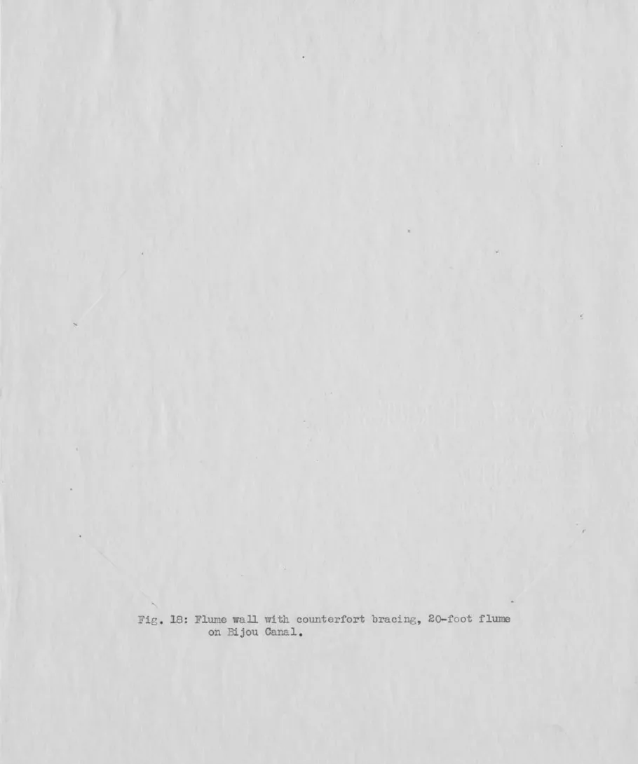
back-fill pressure, countol~forts have proved satisfactory in supporting
walls of ?-foot height on 20-, 30-/ and 40-foot flumes, Fig. 18. It will
be noted in ~ig. g that substantial footings are shown. rrhe base for
should be firm and well prenared, and because of the floor
structure which acts as a base, little' or no settlement has
been observed in these large concrete structures. The lon(litudinal and
transverse bea•1s under the floor
h
~t
.tt
~f
.
f . ,s or 1\ ' o re1n orclll~ oar.
~ y
should have U-shaped pieces., I . bent from
inserted in the top surface of these
beaw2 at ir-tervals such that the bars in the
them to secure rigid contact of the beam and floor. ~ese beaDs provide
strength against heaving or bu.lgir.g of the floor surface.
The essential feature in the buildii'..g of these flumes is to have
15-section should be level~ ·~~~~~~~~~~~~~~~~~~" The downv~ard
sloping floor in the throat should be a plane sUl~face~ leveJ tPaBsv~rs~~
and pitch~~ p to tp.e proP.er dimensions as sho}T!ll. The floor of the diyerging. IVY t'?
j,..,
' I ' • " f , .. ~I , ' ~ ,section is inclinfil upv1ard level transversely. Tlie most irqportant
.
)
feature in the construction of these flumes is the uniformly level floor of
the converging section, and also the uniformly level and straight crest which
is the junction of this floor and the floor of the throat. To provide a
sharp and definite edge to serve as the crest, it is recormnended that a straight
substantial angle-il~on be securely fixed in .,.lace. For the conc1"ete structures this may )e cast in the floor where the ends of the anr,le- iron extend 2 or 3
inches back fnto the side ·walls of the structure. Holes provided ~ the
vertical lee of the angle-iron at about 2-foot intervals, · · _ ._h;t'Which short
pieces of reinforcing steel or bolts rray be inserted and cast into the floor,
will securely anchor the crest in place. It is reco'T:''~'ended that c: ...
angle-iron be placed at the downstrean end of the diverging sec·ttion., if built of
concrete, as a pTotection to this exposed edge. The walls of the structure
should be s~~oth, straight/ and vertical on the inside, and battered on the outside.
pressure
t
in the floor
or the concrete structures t . rovi-de
1
~ent tubes!\ as indicated in Fig. 9.The inclined apron at the upstream ehd of the flume, as well as the
curved walls reaching back to the banks of the channel which serve to lead
the stream of water into the entrance of the flume with slight loss o:f head,
should all be s oooth a.."ld ref,ulnr to insure good conditions
The utility of the structure is in the accurate measuren:ent of the
dis-charge. As the rate of flow is a function of the depth of water in the flume
16-distances to these points be caref~ully determined. Table I gives these
dis-tances to the upper gar,e
1
B'a.
in feet, "'easured back fro11. the enC. of the cresta.lonr, the wall of the convergin.g section. This ?Oint may be located on either
side of the str~cture. Figs . 9 and 13 show inlet tubes leading from the in
-side face of tho wall into the Ea gage well, where this well is cast as an in
-tegral part of the structure. These inlet tubes are set in a vertical line
12 inches apa~t and where the bottom one is about 3 inches above the floor line.
The
the
ture, it is recomn:ended tha.t the first courses of -vvall planks be set and then
floor planks carefully fitted in place. rrhis arrangement insures against the bulging or crowding inward of the bottom vvall planks, due to the hydrostatic
and earth pressu.re against the outside face of the flume wall. Alsq, exper
-ience indicates that the planks should not be m..:2tched too closely. In son1e CF!ses the swelling of the wood has caused the floors to warp or heave, thus
rrak ing an irregular surface • crack 1/8 to 1/4 inch ~
,{1·
-~~etween adjacent planks. Partinp~ stop fillets to prevent lenkaFe is
believed to be unnecessary.
As for the concrete flume, an angle-iron crest is highly desirable. After setting the floor of the converging section where the ends of the planks
at the crest line are srrooth and even, the angle-iron crest should be set flush with the floor surface and held firmly in place with substantial lag
screws. The heads of these lag screws, set at about 2-foot inte::vals, may
project above the surface without material interference the proper working
1'7-at riGtht an:2:les to the axis oi' the flume, and level 'WlPQP[T&.0*'-;"'
~
·-
A
"
For the frame structure, Fig. 13, the curved transition at the
en-trance is foi'Ti1ed by 3 by 6-inch pieces set on end and held in place by 1/4. by i3- inch steel bands properly spaced, where one end is securely bolted to the upstream end of the wall of the converging section and the other to a post firmly set in the bank o~ the channel. These bands, when in place, form a
smooth curve ·to support the vertical :pieces a:nd are} therel held .e' I:I;S-l~t:;~.p by
the back fill.
ri'he framing of these large structures can be accomplished by any ex-perienced carpenter. After the work has been com~J~eted., it is desirable to
trim the tops of posts to a uniform height as a matter of genen3.1 appearance.
Material that is pressure-treated with creosote or other preserva
-tive is fully warranted, from 'the standpoint of economy, in the construction
of the frame structure.
Wooden flumes used on ditches carrying water during the winter season
have been subject to scoring, due to the angular pieces of ice stril-cing
against the side walls of the lower end of the converging section. It is
thought advisable to protect the angle at the junction of the walls of the throat and convergi~ section by means of a vertical strip of heavy weight sheet steel, fomed to the proper angle, so that when in place it will fit
snugly against the side walls.
It has been the practice to provide a subs~antial footbridge span
-ning the converging section, at a point about three-quarters the length of this section, measured back from the crest. This bri(lce is for use in mak -in-::· current-meter gagings and also to provide a means 0f c:rossing.
It is not possible to state the cost of these structures as many
18
-subrntted, it is possible to approximate the a~ount of material, either
in lumber or concrete. The local market prices are then used to estimate
the cost of materials. The excavation necessar~T, accessibility, trans ;or
-tation and othef features ultimately enter into the cost. Treated lumber
flumes should cost relatively less than concrete; however, in some instances,
there has been little difference.
rl1JIE STILLllJG WELLS - - - C,
In the accurate measurement of the discharge t.brovglJ these large
flumes, it has been found necessary to deterrrdne carefully the effective
A staff gage on the inside face of the flume wall for
the deterrrdnation of the
Ra
readiTh3, can be read only approximately be-cause of tl e fluctuations of the water surfacej an.d for the Hb gage in the
throat, the t·urbulent condition makes it entirely impossible to eecure de
-pendablc readings. In order to obtain reliable and accurate f/Ftp,e rendJ. .gs,
u double stilline- well is provided at such a point as to have the {?age inlet
tubes pass directly into tl1e ll'a cornpart:nent, while for the Hb P:ape the head
is broueht back to the other corqpartmen.t tl:t-foll@'h a suj. table pipe leading
from the proper point in the throat section. A reinforced concrete still
-ing well is recommended with a 1/4-inch steel plate diaphragr., cast into the
walls and bottom of the well to provide the two 'l.mter-ti~,ht Ha and lib corn
-partments, Fig. 21. 11 ladder way is sucsgested for each compartment, this
being i~provised by casting U-shaped pieces of reiD~orcing steel into the
~all of the wells at a convenient place.
Because of the depth of these wells, it has been found rather dif
-ficult, as well as impracticable, to clean out the deposit of mud and sand
by means of rope and bucket. Under some condi tior.s, where the water passing
19-these stilling wells become fouled within a short time. As a practical means
of clearing these wells, a flushinr:: system has been developed which has proved
to Lie effective and pract_ical. Leading frorr. the curved wing wall at ·the up
-strea:~1 end of the struct;ure is a 6-inch metal pipe which outlets into the Ha,
stilling well. This pipe has a substantial gate valve, located as shovm in
Figs. 9 and 13. At the outlet end in the well is an elbow pointed downward.
In the steel diaphragm is a 6-inch circular opening near the floor line, and
attached is a good substantial gate valve. TI.1e 6- inch pipe le(:tding from the
Hb well to the throat of the flume completes the systen.
open the valve on the inlet IJipe~ the valve on the steel
the slide gate in the Hb well. Unless the
To flush the wells,
and r.sise
t.:. .. e flume is
very high, the hydrostatic head between the inlet and outlet ends of this
flushing system is sufficient to :provide a good scouring velocity ~~ · t"..b the
two wells. The elbow, pointed dovr.award in the
Ha
well, will move the denositon the inclined floor to1Nard the opening t~'§k the diaphragm, and since the
outlet from the Hb well is at a low elevation, the deposit will tena. to move
to this point and eve_ tually be carried out and discharged back into the throat
section of the flume . Under extreme silt or sand conditions, a 5- or 10-minute
flushing every day should maintain the wells in good order. W'nen all the valves
are closed, the water levels in the two wells will reedi];y as~m.me their normal
elevations •
It will be noted that the valve in the pipe line leading to the Ha well
is shown set back at some distance from the .inlet end. ]1or winter operation,
the danger of dannge to the valve by- freezing is lessened by having this valve
well back fro::1 the eA.l_Josed wall surface. ::Cor (~onvenience in the operc:tion of
the valve., a pit may be provided with a trap door and lock, or e. key stem ex
20-The slide gate at the upper end of the outlet pipe from the Hb well
will not need to be a close-fitting valve. A simple gate may be constructed,
Fig. 19, by using a standard 6-inch cast-iron flange loosely turned on the
:project inc end of the pipe. .lt lue and cover~ plate prepared as sho1.m, bolted on opposite sides of the flange, serves as guides for the slide valve. mhe
latter rray be made of 1/8-inch steel plate, cut to dimension as shown, with a lon~ handle e:;ctendine; up to the top of the well. Insert the slide gate
into the guides and then the lovrer hole in slide. This bolt head will then come in contact with the bottom edge of the inside of the pipe and stop the gate in its proper.position, and will, in like nanner, prevent the gate from being withdrawn from the guide.~ • Vlhen this slide VIJlve is in nor1nal position, the 3/4-inch ·hole is near the top side of the pipe O')en
-~
ing and is intended to damp down the pulsations caused by the roughness of the water in the throat of the flume. If deposit occurs in this 6-inch pipe line, it will occupy the lowest portion leaving some space at the top for the com -rnunication of the water pressure.
GAG~ HOUSF. lt:FD
'l'he gage house built over the stilling wells is not indispensible
as a shelte:r· for the instrurJent, but is in ~ceeping with the utility of the installation. Experience shows that the convenience afforded by providing a sui table shelter warrants its cost. As shown in the several pictures of
these large flumes, the gage houses are of neat apnearance, built of drop sidin"·, shincle or metal roof, hard pine floor, 4-light Vfindo s, and a
well--painted e:xterior. '1o -16 have been finished inside rli th :xmeled wall boa.-rc., and all have a built-in cabinet over the gnco wells on v~~ich the recording
instrument is mounted . r:.he elevation of thE: top o:L the cabir,et above the crest must be co1-:sidcred. This height should be sufficient to ~ rcvent the
21-counterweie,ht from striking the top of float for the maximum star-e or depth of water in the flume. 5or a range of 5 feet in depth, t .e base of the in -strument should not be less than 10 feet hir,her than the crest of thE: flume.
In general., this height above cl~est should be sonevmat more than twice the
maximum
lfa
gage height • The plane of the front side of this cabinet agrees approxi?.::.ately with the center line ~the two gp.ge wells. The remain-in:3 area of the top of· these wells is covered by a trap door, hinged at the edge, so the opened door will lie flat on the floor of the house, exposing
,.--______
~--
-'the hand wheel on extended
ste
li~G
• thineas~for
operating the 6-inchI
-gate valve on the steel diaphrag,m aft+i. ikewise the handle of the slide gate is '.li thin easy reach. The ladder into the wells should be located on the wall or across the corner noo.r the trap-door opening. The front side of
the cabinet should be provided with two doors, hinged at the sides and equipped
with cupboard l atch. These doors when opened, together with the traJ.) door, :provide sufficient illumination iL the wells for observation.
The double-head indicating and recording instrument , esJecially desifmed for use in connection with the large Parshall measuring flumes, Fig. 20, has proved to be well suited and of practical design. This instru-ment, whose base is 8 by 21! inches and 17;'"" inches high, is equipped with a vertical clock cylinder which carries a pecially designed convenient chart, and turns one revolution in
7i
days. The recording range of gage height is 5 feet .point.
The clock used is hig~ grade;&~•-~
0 .
and is A
a friction gear
f
.._.
setting the chart to the correct time by merely turning the cylinder to the desired On trro independent rotating shafts, suitably mounted on the base of the instrunent, two drums are fixed which indicate the Ha and Hb gage heights. Each of these is moved b~,r a sprocket wheel and chain, where the
22-latter is attached to a float in the well, and the s:>rstem balar~ced by a counterweight. The go..ge heti.ghts,
ITa
and Hb are read on a contin:~ous ,sp i-raled grac1ue ted scale, in feet, on the surface of the d n1ms, where these scales are of neat, clear-cut rmrkings printed on white pyralin strips which are afterward formed into cylinders of the proper dian.eter and :provided withheavy pyralin he.ads, securely fixed to the sprocket-wheel shaft. :Mounted
on a brass support is a strip of clear pyralin with a fine black-etched line spanning across the face of each cylinder. Any change or variation of the water surface in the wells is indicated by the movenent of the scale beneath this index line. rrhe drum at the left, Fig. 20, shows the value of the Hb
head, a"1d at the richt a wider-faced drum bearint two sets of graduations, one the
Efa
and the other in bold-faced type;s11owine; the rate of free-flo"cllfdischarge in second-feet. T'ne ~ drum with dische.rge graduations is de
-sicned for any particular size of flume.
rrr1e two pens used to scribe the grauhs on the graduated chart are
mounted on a suitable head block carried at the upper end of a vertical
rack, neshine with a small gear of proper diameter attached to the shaft
carrying the sprocket wheel and indicating drum.
Parallel guide rods direct ~~he pen vertically along the hour line
of the chart. J~ach pen is synchronized to the drum reading for gage height,
and since the index line crosses more than one line of graduatiol1_s, it is
only necessary to read approxin:a tely the indicated chart reading and then
observe to close limits the actual value of tihe head as shm•fn on the drum.
In the operation of this instrurnent, the only manipulation necess
-ctry is to remove the clock c"~rlinder, wind, and change the chart • To renove the cy-linder, the Ha and Hb pons are lifted from the chart by a sui table lever arrange~.~ent, and the cylinder is then lifted vertic2lly from its pivot supiJort. The key for windinr-_::: is attached to tho clock rr:ovement and extends
23
-to the top of cy-linder. An ornamental cover fits snugly over the top as a protection. rn.e blar.J: chart, cut to fit, is laid arounct the cylinder e.nd rests against a rinc projection at the bottom. Rubber bc-.1 ds are used
to hold the sheet in ple,ce; however, paste :may be used to sea 1 the ed~es.
The distance between sprocket w 1eels is 18 inches, anc1 where 12- inch floats are used )only 6 i~ches are available to clear the vertic~l diephravns in the float we ·L..l. If a concrete partition welJ. be used to separate the Ha and Hb comuartments, it has been found that for a practical thick __ ess of wall there is not suffici.ent safe rnargin or clearance for the travel of
the floats. The· metal diaphragrn, with horizontal angle-iron stif~ers
. j
which occupy only about
2;}
inches, is much rrJ.Ore suitable. To properly---e
the :position of the instru.r:1ent on the top of the cabinet, it isnecessa...or to plumb carefully from t~hragm up to the under side of
the top of the cabinet and here drive a nail. From this point
"
onA top side, the holeAfor the sprocket chains and also holes
vrhi ch the pen racks pass To provide ample clearance, l-inch auger holes are recorrn~ended. T'ne instrmr..ent base is now shifted
to position and firmly fixed by screws at the ends. r:b.e SlJrocket chains
are threaded/\~ .. tgh, and float and counterweight attached. ~e mounting
and setting of the instrument reqllire no special exnert meche,:'..ical skill.
ey carefully detern1ining the mean crest elevation, usinr? an engi -neer's level and rod~ a bench mrk is set over each well. 'Ihe elevation
of these marks above the mean elevation of the C'.J.,est is C'alcnlated end posted at each of these refcr·ence points or bench marks . ':::his difference should be shown to 0.001 foot. A special weig~ted hook-gage ettached to
a light weight steel tape, graduated to 0.01 foot, is used to determine the vertical d~tance between the uater surface and the fixed reference
24
-point, 2.,ir;. 21. To use t 1is hook-gage ulura.b bob, attach it to the rinr" of the steel tape and lo rer it into the water in the well until the point is submerced. Carefully xaise until the point just appears, and then read taue at the reference point. This tape reading 'VI ill, of course, be the distance
to the zero point of the tape. To this :must be added the distance, A",
from the point of the hook to the zero point of the tape. The surn is then
the distance fror:1 the reference point to the rater surface, and this sum subtracted from tho elevetion of the reference point will be the actual ef
-fective hoo.d. Observe the drum readin on the instrument at the same time
the hook-gace reading is taken, the resulting difference indica tine.~ the
error in the instrument reading. In setting the instrument for the first tirre,
considerable error nny be expected. Th- T"'.OVing t.1e chain on the sproc :et, a large correction m~y be made u~til a fai~ agree~ePt is 2ttained. Several
hook-gage readings should no·;; be taJ~en and also
1 s irrrulteneously1 dru.m rec din s .
The mean of these observations '.7ill indicate the e~tent of the d viotion which nmst be m, de by adjusting the lork-nut attaclwent at the float. The
comparison of both drums ana. final adjustr,ents must be made before actual
dis-charge calculations are possible.
V
measuring flume for all sizes has been taken as that condition of flov1 where the degree of sub
-mereence does not retard or resist the rate of discharge. As the water the throat section, it rray asslwe two different ·nd distinct
stc:ges; first, ·nhore the velocity is high and the stream flattens out and conforms very closely Tii th the dip at the dorms trea:!:l end of the throct sec
-tion; second, vtlere the depth of water in the channel dovmstream fra the structure is such as to cause a hydraulic jump or standinr.:: vmve to forn in
n once 1r the
ed by .addressi. olli s .
1 -he d
o-
25-the lower portion of ths throet.
If the degree of subEergence is great enough, this standing wave is
moved unstrear~ in the throat until this resistance is sufficient to retard
the rate of flow. For all concition.s of flow uu to this linit:Lng der,ree of
submerrcnce, the rate of discharge is unrestricted, constant and fixed; hence,
because of tho application of a definite law of flow, this range is ~alled
free-flow. :7or the srrall flumes, 3- to 9-inch thrrots, t 1is limitin~· degree
of submergence is a~Jroxbrr~tely 50 percent, while for the 10- to 50-foot
flumes the practical limit is taken at about 80 percent.
m
1
•
~
1.522 W 0•026,
Yne free-flow discharge for1rula, Q = 4 11 ·~ for the small
flumes 1 to 8-foot size, when extended to the large structures is found to
give the discharge in excess of the actual flow. In developing the general
discharge formula for the large flumes, a more simplified expression has been
found applicable for flumes ranging in size from 8 to 40 feet. '='he general
1 6
discharge formula is Q, • (3 .6875W + 2 .5) Ha_ • , where Q is the rate of
dis-charge in second-feet, W throet width in feet, and
Ha
the upper gage in feet.The discharge computed by this forrmla for an s-;root flune differs by less
than 1 percent fran the general expression applicable to the smaller flunes.
Tables II to IX give the di-scharge in second-feet for throat wtdths
10, 12, 15, 20, 25, 30, 40 and 50 feet. By estirration, it is possible to
determine the discharge in second-feet within an accurt~.cy of less than 1
percent.
?or tho small-size flumes, the free-flow condition of discharge is
highly desirable, because only one gage height or depth is involved in
de-termining the rate of flow. Here the exit velocities are relatively high,
but as the amount of water is not great the resulting effect of erosion
26-500 or 1,000 second-feet are being discharged under a condition of free
flow, then the matter of erosion due to the hi[2',her velocities, partir.ularly
in soft materials, presents a problem for· consideration, Fig. 6. It is b e-lievedJwhere the banks and bottom of the downstream section of the channel
would be subject to considerable cutting,it is the better practice, generally,
to set the larger structures so that a submerged condition of flow \7ill
re-sult for the higller discharges. }?or the submerged flow, both the upper gage Ha and the throat gage Hb must be considered in the detenn.ination of the rate
of flow.
To determine the rate of submerged flow, the ratio Hb to Ha is ex -pressed deci~lly and taken as the percentage or degree of submergence. Fig. 22 is a correction diagraril showing the amount in second-feet to be deducted from the free-flow discharge for that particular value of
Ha
.
At the left, vertically, are given the values of the upper head, Ha, in feet .
Crossin~ the diagram diagonally are straight lines indicating the ratio
Hb/I-Ia or degree of submergence, and alone the base of the diagram is the cor
-rection in second-feet.
To illustrate the use of tt is correction diagram, let it be required
to 20-foot Parshall measuring flume, where
the up:p er head, Ha, is 3 .25 feet and the Hb or lower head is 3 .06 feet •
The ratio 3•06/3.25 is 0.941. In the diagram, find the value of
Ba
at 3.25feet, vertically along the left-hand side. Now, move horizontally to the right to the diagonal line 94; then, by estimation, advance 1/10 the distance between the lines 94 and 95 • Vertically below this point, the correction of 56 second-feet is indicated. From Table V, the free-flow discharge
~ the 20-foot flume for an upper head
Ha
at 3.25 feet, it is found that the discharge is approximately 503 second-feet. The submerged flow,I
then, is 503 - {2 x56, or 391 second-feet. The correction is determined in
27--l
the same rnanner from this diagram for submerged flow 'ihPGa8l1 other sizes of flume . For a 10-foot flllr!le, the correction is as shown by the cliar::ram; for the 12-foot flume the correction as indicated by the diagram is to.be
multiplied by 1.2 before subtracting from the fi'ee-flow rate of discharge.
nhe follmvinr; table gives the mul tiplyint; factor for correc+ i! "; t .. e ind
i-cated value from the diagram for the various sizes of flume:
Size of flume :r..m1 t iplyin.g Size of' flume rvTul tiplyi!lg
.!:> u c t 0 r ..(:0 a c t 0 r l. J. ~,;~ in feet VI in feet 10 1.0 25 2.5 12 1.2 30 3.0 15 1.5 40 4.0 20 2.0 50 5.0 LOSS OF HEAD
c.,
IIn the design and setting of these large flumes, it is frequently
necessary to kno·w, within reasonable limits, the total loss of head 'tfl:J?SQ~h
the structure. It not infrequently happens that it is quite impo1~ant to determine beforehand the hish-w.ater line in the channel upstream from the flume before installation. In the final selection of the size of flune
which is to meet tho requirenent as to capacity, loss of head, degree of
submergence, and free-board in channel, it is believed that the diagram,
Fie. 23, will be found useful in the selection of the pro~er size of struct~ure.
This diagram is based on the formula
- _1---:..----::-=-- ( 100 5-
s
\
L= 1
;I
(W + 15} •46
0.72 0.67
Q
where L is the total loss of hea.d in feet :t;h: .... eugh the stn cture, the size
of flume or width of throat in feet, S :percentage of submergence, or ratio
"I
/')
L
Table X ((fomparison of u.rrent Meter measurements with·
Date H e a d s 4-4-29 4-5-29 4-5-29 5-3-29 5-3-29 5-3-29 Ha H b Feet Feet 0.78 .79 .?9 .83 .83 .82
....
.
.
.
.
....
....
....
....
flows computed by formula;for Parshall measur -ing flunes of various throat widths.
FORT BS:N'T CArAL, 10-foot flume (Staff gage in stilling well)
Ratio D i s e h a r g e Hb/H Current Differ-a meter ence Percent Sec.- Se c.-• ••• ••••
. ...
• ••• • •••.
...
*
See Fig. ft . ft . 2? .1* 27.
a
2? .7 29.6 28.7 28.7 24 26.5 27.0 27.
o
29.2 29.2 28.7 0.6 0.8o
.
?
0.4 0.5o
.
o
Devia- Method tion percent + 2.3 -+ 3.0 + 2.6 + 1.4 - 1.7o
.
o
2/8 2/8 0.6 2/8 0.6 V.I.LA..S ANJ:1'tf3 C01L30LIDli.TED c..:\..l:AL, 10-foot flume (Staff gage on flume wall)
5-12-26 1 .15 5-13-26 1.71 5-13-26 1.99 7-26-26 1.16 9-17-26 0.48 9-20-26 .51 9-22-26 .43 7- 1-2? 2.05 8- 4-28 1.18 7-12-29 1.22 5-14-30 1 .09 5- 3-29 0.78 5-16-29 1.65 6-18-30 2 .21 6-19-30 2 .21 6-19-30 1.96 6-20-::"0 1.91
. .
.
.
.
.
. .
....
. .
.
.
.
.
.
.
.
.
.
.
. .
.
.
. .
.
.
....
....
.
.
.
.
2 .02 2.
os
1 .79 1 .67 • • • •....
....
• ••• •••• •••• ••••. ...
....
49.5 96.1* 120.4 50.2 13.0 14.3 10.5 127.6 51.4 • • • • 54.2~ee
.
F
f
~
.
1 42 • 9 49.3 92.9 118.4 49.9 12.2 13.4 10.2 124.2 51.3 54.1 45.3 0.2 3.2 2.0 0.3 0.8 0.9 0.3 3.4 .1 .1 2.4PD-ffi RIVEH CAITAL, 10-foot flume
.
...
....
25.8 26.5 0.7 87.8 4.6 +0.4 +3.4 +1.7 +0.6 -t6 .6 +6.7 +2.9 + 2.7 +0.2 +0.2 -5.3 -2 .6 +5.2JIOJ.EHOOK HEJERVOTh OUPLET, 10-foot flume
(Staff gage i~ stilling wells)
91.4 94.1 91.3 87.4 123.5 118.1 105.8 101.2 123_.0 114.5 102!t6 104.9 0.5 3.6 3.2 3.7 +0.4 +3.1 +3.1 -3.5
V
.
I
•
"
tt 0.6 ff V.I •"
2/8 0.6"
0.6 2/8 2/8 2/8 Hydrographer Parshall Owens Parshall Rohwer"
"
Parshall Curtis"
Rohwer"
.Parshall Owe:r:s Willian.E"
Owens"
Date H e a d s 'Weet Yeet 2-16-28 0.66 2-17-28 1.57 2-17-28 0.92 r.:-17-28 1.28 4-12-28 1.03 4-20-28 1.01 7-12-28 1 .04
a
-
5-28 1.oo 7-13-2 g 1.21 7- 2-29 tf -2,07 1.66 1.34 0.78.
.
.
.
.
.
. .
....
.
.
.
.
.
.
.
.
....
.
.
.
.
.
. .
.
....
....
....
D i s c h a r g eCurrent com.:.. blfi'er
-mcter puted ence
Percent. i3ec
.-ft .
Sec.- Sec
.-ft. ft.
OT.t:Ho C!-'d:!AI", 12-foot flume
(Staff gage on flune wall)
.
...
....
....
....
.
...
....
....
.
....
...
24.4 97.
o
39.4 71.7 50.0 48.4 45.8 46.3 61.6 24.1 96.2 40.9 69.4 49.0 47.5 49.8 46.8 63.4 0.3 0.8 1.5 2.3 1.0 0.9 4.0 0.5 1.8 "'Jevia -t '.on percent +1.2 +0.8 -3.7 +2.0 +1.9-
s
.
o*
-1.1 -2.8 r-ethod V.I • tt tf tt"
ff"
tt H;rdropra"'lher Parshall n n Curtis tf Par·sha11 Rohwer ParshallHO:JSE CllY..EJC IJ T~J,L (Torrir..gton, i,Vyo.) 12-foot flume
(Staff gage in stilli~~~ well)
•••• 148.9 149.?*
o
.
s
•••• 106.6 105.2 1.4 •••• 74.1 74.7 0.6 •••• 31.3 31.4 0.1 -0.5 +1.3 -0.8 -0.3 V.I •"
Rohwer"
tf______
_...--·-*
.see- ;-;·~· '2 s 8- 3-26 ff 8- 4-26 8- 5-26 8-17-26 8-19-26 8-31-26 ?-26-2? 8-26-27 0.89 0.89 0.95 0 .93' 0.66 1.19 1.19 1.04 0.86 1.28* 1.4-1* 9- +-29 1.70 4-14-31 2 .48 6-10-30 6-11-30 8- 8-30 11-6-30 4-15-31 1.77 1.73 1.71 l 27 1.35....
....
....
....
.
.
.
.
.
. .
.
....
.
. .
.
....
....
. .
.
.
BO"': ELDEr CPIK, 12-foot flume
(Staff gage on flume wall)
• • • • 37.6 38 .? 1.1 -2.8 -r; .I. '")ohwcr • • • • 38 .8 38 • 7 0 .1 +0 .3 '' Pai'sha 11 42 .1 43 .1 1 .0 -2 .3 " =-~ohuer
.
...
41.9 41.6 0.3 +0 .7 "1 '1....
24.3 24.
o
0 .3 +1.2 " PaTs ball....
60.3 61.8 1.5 -2.4 " n 6l.o 61.8 o.8 -1.3 ff "....
48.4 49.8 1.4 -2.8 " " 38.1 36.7 1.4 +3.8 " " •••• 72.7 69.4 3.3 +4.8 " " • • • • 87 .4 83 .8 3 • 6 +4 .3 '' "?ohYTer*~ ... "'a gage checked Ju 1 y, 1 93 1 , and found to be 0 .06 ft. high.
PIJ~ RIV~:S, 12-foot flume
....
110.7 109.3 1.4 +1.3 0.6 Hil1iaiP..sCATLDJ ClD~AI .. , 12-foot flume
(Heads indicated by instrument, Fig. 20)
1.74 70.0 195.0 200.0 5.0 -2.5
...
Burgess....
0.52 0_,86': 1.23 See Fig. 26ROCIL" "FOHD CArAL, 12-foot f1UI2e
(Heads indicated by instrument, Fig. 20}
•••• 114.1 116.5 2.4 -2.1 •••• 109.7 112.3 2.6 -2.3
zo
.
•
o
108.2 110 .2 2.
o
-1.8 68~n GB.9 68.4o
.
5
+0.7 91.1 66.5 68.6 2.1 -3.1 2/8 ff Owens Parshall BurgessDate D i s c h a r g e r::urrent nom-
Diff-meter nuted erence
Jevia-tion Feet Feet
Per-cent
Sec.- Sec.- 3ec.-
per-f t. ft. cent 3- 5-30 0.60 5-20-30 1.16 8- 7-:::0 1.25 4- 6-31 1.50
-12-4-30 5-24-31 5-26-31 0.85 4.61 1.39\""---~
12-8-2 '7 12-0-27 2-12-28 2-14-28 2-15-28 2-17-28 2-18-28 3-14-28 3-1:1-28 4-29-28· 5-11-28 5-12-28 5-13-28 5-17-28 7- 8-28 '7- 9-28 '7-12-28 11-1-28 11-30-28 1.oo 2 .65 0.84 1.57 2.30 0.93 0.88 1.08 1.43 1.00 3.40 3.45 3.03 3.31 2.27 1.56 1.57 1.42 2.08....
....
ft .FO:ST ID~~ C.,...Lt..L, 14-foot flume
(Staff gage in stilling well)
•••• 23.4 23.9 0.5 - 2.1
•••• 70.3 68.6 1.7 + 2.5
Lu.AP.. CJJ,-AL, 15- foot flume
(Heads indicated by instrurrrent li'ig .20)
• • • • • • • • 83 .. 0* 82 .6 0.4 +0 .5 •••• •••• 111.8 110.6 1.2 +1.1
*See Fig. 2'7
11QC?;:;[ FOP.D HIGHLII3 C.AH.::..L, 15-foot flur~e
(Heads indicated by instrument, Fig. 20)
.
.
. .
.
...
4.37 94.8 .26 19.
o
*See Fig. 11; 45.5 44.6 463.7* 478.5 100.8** 97.9**
See Fig. 10 0.9 13.8 2.9HOLBROOK C.A1TAL., 20-foot flume
+2
.
o
-2.9 +3.0 (Heads observed by s_ ecia1 indicatine tapes) 0.82 82.0 74.5** 75.4 0.9 -1.2 2.58 97.4 248.0 240.5 1.5 -0.6 1.31 1.81 0.43 0.38 1.10 0.25 2 .14 2 .?9 2 .14 2.08 0.74 0.50 0.60 1.15 1.86 •••• 55.8 57.7 1.9 -3.3 83.4 155 .9 153.8 2 .1 +1.4 78.8 287.4 289.1 1.7 -0.6 46.2 66.8 67.9 1.1 -1.6 • • • • 63 .1 62 .1 1.0 +1.6 35.2 88.3 86.2 2.1 +2.4 77.0 139.0 135.2 3.8 +2.8 25.0 77.2 76.3 0.9 +1.2 63 .o 547.5 81.0 546.0*** 70.7 453.4 62.8 529.9 32 .6 2?2 .7 31.8 161.6 38.2 160.2 81.0 130.0 89.4 22'7.0 540 .. 3 51.1:4.8 449.8 517.6 283.1 155.3 156.9 132.2 225
.
o
7.2 1.2 3.6 12.3 10.4 6.3 3.3 2.2 2.0 +1.3 +0.2 +0.8 +2,4 -3.7 +4.0 +2.1 -1~.7 +0.9 3- 8-29 2 .07* 1.80 87.
o
249.5 230.8 18.? 1.9 1.1 6.9 +8.1 -1.1 +0.9 +4.1 +4.1 5-14-29 1.71 1.24 72.5 178.0 179.9 5-28-29 1.55 1.50 96_8 119.1 118.0 6- 4-29 1.94 1.87 '/6 .• 4 174.1 167.2 8- '7-29. 4.97 4.68 94.2 75?.2 727.0 9- 2-29; 2 .36 2 .13 90.3 280.7 269.
o
2-17-30 1.80 1.51 83.9 196.1 190.3 8- 6-30 3 .55 3 .16 . 89.
o
504.
o
521.0 30.2 11.'7 5.8 1?.0 ~.r.ethod H:;;dro-f'r2·pher 0.6 2/8 2/8 2/8 2/8"
V.I. 2/8 0.6 2,l8 t7 n 2/8"
tt n 2/8 ff ft"
ft n fl Owens n Parshall Owens Pars1nll Tt Rohwer uarsha,,
l l,,
"
ft"
Curtis Pa!"shall CUrtis Parshall r::ode Parshall"
ff Owens"
Parshall Owens"
Parshall""T"r~his value believed to be in error·. **.-See

![Fig . 5: ]lorty-foot Parshall i:leasuring l~'luro.e, discharge 17'7 second- second-feet, no subnergence, Fort LYon Canal](https://thumb-eu.123doks.com/thumbv2/5dokorg/4322577.97604/45.939.11.925.27.1138/parshall-leasuring-discharge-second-second-subnergence-lyon-canal.webp)

![Fig • . 11: ],ifteen- foot Parshall M easurinG Flume, discharge 464 second- feet , submergence 95 percent](https://thumb-eu.123doks.com/thumbv2/5dokorg/4322577.97604/50.937.30.914.26.1141/ifteen-parshall-easuring-flume-discharge-second-submergence-percent.webp)