Scienpress Ltd, 2016
Mosul Dam the Full Story: Engineering Problems
Nasrat Adamo1 and Nadhir Al-Ansari 2Abstract
The idea of building of Mosul Dam project started in 1950 and it was referred to as Aski Mosul Dam. Since that time, number of companies worked on the site selection and design of the dam. All the above companies suggested that the dam should be Earth-fill type with compressed clay core but there were different views about the exact location of the dam, spillway and electricity generating station. Grouting was suggested to be performed under the dam, spillway and the electricity generating station. In addition, they suggested that detailed geological investigation should be performed before any construction activities. In 1978, the Swiss Consultants Consortium was asked to be the consultants for Mosul Dam project. The consultants suggested that the operational water level at the dam to be 330 m (a.s.l.) while the flood and normal water levels to be 338 and 335 m (a.s.l.), respectively. The work started on 25th January, 1981 and finished 24th July, 1986. The foundation of the dam is built on alternating beds of limestone and gysum. Seepages due to the dissolution of gypsum were noticed and after impounding in 1986, new seepage locations were recognized. Grouting operations continued and various studies were conducted to find suitable grout or technique to overcome this problem. The seepage due to the dissolution of gypsum and anhydrite beds raised a big concern about the safety of the dam and its possible failure. It is believed that grouting will not solve this problem permanently.
Key words: Mosul Dam, Karstification, Grouting, Sinkholes, Iraq
1 Introduction
It started in 1950 with the Iraqi development board (IDB) decision to expand the irrigated area in Iraq for increased agricultural production and to protect the capital city Bagdad from the recurrent destructive floods. Mosul Dam on The Tigris River was one of a long list of dams including also Bekhma Dam on the upper Zab river and Dockan Dam on The lower Zab river, two of the tributaries of the Tigris which flow into it south of Mosul north of Baghdad, and Derbandi Khan
1
Consultant Engineer, Sweden. 2
Dam on The Diyala river an another tributary which outflows into the Tigris just south of Baghdad.
In 1950, (IDB) tasked two British firms to locate a dam site north of Mosul city and to carry out some geological investigation works and submit a preliminary design of the dam, which they did in 1953. But due to the questions raised by an international reviewing board and the changes of requirement to irrigate Al-Jazera area (250,000 hectares) and then increasing the irrigated area by another (750.000 hectares) in the middle and south of Iraq, all this resulted in inviting four more consulting firms one after the other to carry out more investigations, select different axes of the dam, submitting different designs during the period 1953 to 1978.At this last year the Government gave the green light to go ahead with the construction of the dam after arranging for another extensive geological investigations. The Government signed a contract with The Swiss Consultants Consortium to prepare the planning report, final design and tender document even before completing the ongoing investigations. It is worth mentioning that all the previous Consultants had agreed that the whole area suffers from the presence of soluble gypsum rock and thin layers of clay, so very extensive grouting works would be required.
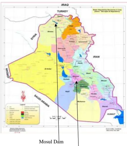
2 Location of Mosul Dam
The dam is located 60 km North West of Mosul city and 80 km from Syrian and Turkish borders. It is about 500 km. north of Bagdad the capital, and some 650 km. measured along the course of the river. A flood wave which could originate from Mosul Dam failure could reach Baghdad after 48 hours only.
.
Mosul Dam
Mosul City
Mosul Dam Baghdad
Figure 2: Mosul Dam Location
3 Mosul Dam Scheme
The final design of the Mosul Dam scheme is comprised of three distinct parts which are functionally connected. First is (Mosul 1), this is the main dam and power station. Second is the reregulating dam (Mosul 2) which is 8 kilometers downstream of the main dam, and finally the third part which is the underground pump storage power plant (Mosul 3) located in the right bank downstream of the main dam. The three parts are all integrated in a system to regulate and reregulate the river flow for maximizing irrigation and power generation benefits while Mosul 1 retains the flood control function. Mosul 1 consists of the main earth fill embankment with its central clay core, main spillway, an emergency spillway, two bottom outlets and finally the main power station (750 Mw); Mosul 2 or the reregulating dam, an earth fill dam with a (60 Mw) power station and Mosul 3 which is equipped with pump-turbines of (200Mw) total capacity. The Mosul Dam is the subject of this paper which deals with the problems encountered in its foundations threatening its stability and pauses a big threat to the population
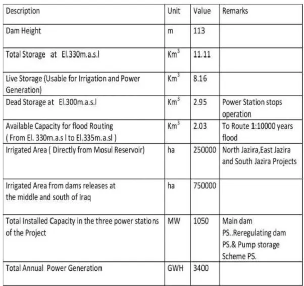
living in the Tigris river flood plain downstream. The maximum operational water level is fixed at EL.330, while the maximum flood and normal flood water levels to be at EL.338 and EL.335, respectively. The foundation treatments of the dam were the grout blanket under the clay core and a deep and thick grout curtain as anti-seepage measures.The importance of Mosul Dam to Iraq cannot be overemphasized being the largest dam in the country and the fourth in size in the Middle East and the one which contribute the largest regulated water supply to Iraq population and Irrigation. The work was started on construction of the scheme on 25th January 1981 and completed on 24th July 1986.The three parts of Mosul dam Scheme are shown in figure (3). Figure (4) gives details of the Main Dam itself. The Total cost of the scheme was 2.6 billion US dollars at the price levels of 1985. The operation parameters of the Main Mosul dam are shown in table (1).
Figure 4: Details of the Main Mosul Dam (Courtesy of USACE).The upper reservoir of the pump storage scheme is clearly visible in the upper left corner of
4 Mosul Main Dam-General Arrangements
Below is figure (5) which shows the general layout of Mosul Main Dam and a typical cross section in the river section. Figures (6),(7) show various views of the dam.
Figure 5: Mosul Main Dam – Layout and cross section
Figure 7: Downstream view of the Mosul Main dam Showing Bottom outlets and Power Station
5 Geological factors influencing the safety of Main Mosul Dam
It is not intended here to go into the details of the geology of the site as this is explained fully somewhere else [1]. However, the main geological factors influencing the dam safety are given below and their effects will be discussed later. These factors are:-
1. The karsts prevailing in the dam site and in the reservoir area.
2. The existence of gypsum/anhydrite rock formations in dam foundation
alternating with soft marl layers and weathered and cavernous limestone beddings. 3. The presence of an extensive ground water aquifer called Wadi Malleh
aquifer which affects considerably the ground water regime in the right bank Figures (8), shows the extent of the karsts phenomena in the form of sinkholes upstream area of the dam and in the reservoir.
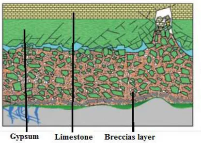
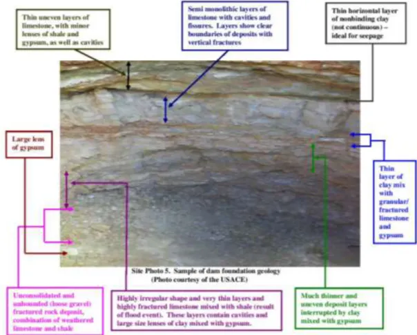
The sinkholes in the reservoir itself shown in figure (9) were mapped by a recent bathymetric survey which was carried out in 2011 by a Luleå university PhD student [2]. It is considered here that the development of such sinkholes will open new connections with the groundwater aquifer running below and around the dam site causing more problems of dissolution and formation of new sinkholes. The dam foundations itself is very complicated and the combination of gypsum/anhydrite layers with the cavernous limestone give rise to very favorable conditions for seepage and dissolution environment. Figure (10) gives a representative picture of this condition.
The existence of highly karstified and jointed limestone layers in the dam foundations gave rise to the formation of highly developed conduits and caverns which form easy conduits to the flow of ground water. This had resulted in the extensive dissolution of gypsum and gypsum anhydrite rocks present above and below these limestone layers. These dynamics caused the collapsing of whole layers of clayey marls into the underneath cavities forming beds composed of brecciated gypsum particles and anhydride blocks embedded into a loose clayey matrix. Four such layers were discovered during the geological investigations and
were called the (Gypsum-Breccias) layers. These layers had thickness which ranged between (8) meters and (16) meters. The first layer was found at a depth of (80) meters in the river section and it was marked as the (GB0) layer. The other three layers were at higher levels. The last one i.e. the (GB3) was discovered at the foundation of spillway chute ski jump. The (GB) layers proved to be very important due to their erratic behavior during the grouting of the deep grout curtain under the dam. Figure (11) shows the geological cross section under the dam. Figure (12) gives the litho-logical column under the Mosul Dam central part.
Figure 8: Enlarged Google Earth image showing many sinkholes (Dark spots encircled by red color)In the upstream area of the dam site [3] [4] [5] [6]
Figure 9: Sinkholes present in the Reservoir [2]
In figure (13) the dotted line is the estimated karsts line in sections 69-87 which is the problem area as visualized by the designers. This hypothetical karsts
line was estimated from the in situ permeability tests results in the boreholes drilled along the axis of the dam during the investigation. The dark dots on and above and on this karsts line indicate some of the areas of major grout take .Below this line according to these tests and designer’s judgment karsts diminishes considerably and cease to exists. These results were used as the defining criterion for fixing the depth of the grout curtain. The design went further to add another 20 meters to this depth for ensuring the cutting out of any seepage path that might have been missed in these permeability testing.
Figure 10: Foundation layers in Mosul Dam foundation (courtesy of USACE)
In Figure (14) the schematic diagram shown explains the process of the gypsum/breccias layer formation. Groundwater flowing through cavernous limestone and gypsum beds had resulted in the development of larger cavities in these limestone and gypsum beds, causing the collapsing in of gypsum, limestone and clayey marls filling these cavities and so forming a complex structure mainly of clayey material of very fine particles in which gypsum bits and particles and anhydrites blocks and even limestone flakes are embedded. These breccias layers due to their structure did not accept normal cement grouts or chemical grouts and many areas in the grout curtain within these layers could not be sealed and even
opened again under increased hydrostatic pressure which caused piping of the fine particles.
Figure11: Geological Cross Section along the axis of the dam. (Due to the length of the cross section is segmented here into parts which are stacked on top
Figure 13: Estimated karsts line in the problem area (sections 69-87).The dark dots show locations of some of the major grout take areas [7].
The groundwater regime was studied carefully during construction especially in connection with the construction of the pump storage scheme underground cavern structures and the intake/ tailrace tunnel. The amount of seepage flow was very large and the excavation of the caverns was only possible after performing extensive grouting works all around these caverns which also served as protection shells around theme and by driving drainage tunnels all round these caverns to remove the drained seepage water.
Similar seepage springs were encountered in the excavation of the tailrace tunnel and its intake structure. Grouting of these springs required extensive grouting works, and the continuation of the tunnel excavation was only possible after grouting the excavated face stage after stage. The quality of seepage water was much different from the river water quality and it contained a much higher concentration of Sulfates. Further studies showed that this water belonged to the very large Wadi Malih aquifer which is being fed from long distance upstream and which was running below and independent from the river aquifer. Figure (15) shows the water flow which was encountered during the excavation of the tunnel and which took considerable quantity of grouting until it was sealed works.
The Importance of the Wadi Malih aquifer is not only due to the great difficulties it had caused during the construction of the pump storage scheme; But also that it shapes the ground water flow regime in and around the right abutment of the dam in addition to the fact that it contributed to the formation of a series of sinkholes at the right bank downstream of the main dam as explained later on.
Figure 15: Flow (360 l/sec) from Underground aquifer into the intake/tailrace tunnel of the pump storage Scheme originating from Wadi Malih aquifer
6 Grouting in Gypsiferous Formations
Grouting such formations proved to be very tricky operation. As such grouting begins to seal some seepage paths, this resulted in an increase of the hydraulic gradient locally in adjacent parts. James and Kirkpatrick [8] explained
that water passing over gypsum becomes chemically saturated within a flow path and in this zone of saturation no further dissolution occurs. As flow continuous, the zone moves downstream and eventually passes from the exit. At this stage, dissolution rates accelerate again sharply. Results of studies of Morrison-Knudsen Engineers Inc. [9] also confirmed James and Kirkpatrick findings regarding sensitivity of gypsum solubility to hydraulic gradient and flow. Their report indicated that for seepage velocities of 10-4 cm/sec in a 2 cm wide gypsum vein it should dissolve at a rate of few centimeters per year from an advancing front. If the velocities were about 10-2 cm/sec. the gypsum could dissolve at a rate of 9 meter per year. Dissolution normally occurs until seepage water reaches a calcium sulfate saturation of 2000 ppm. Hence the dissolution zone moves downstream as greater quantities of unsaturated water attack a gypsum vein.
From Soviet experience gained by soviet engineers from the design and construction of dams in eastern Siberia and central Asia on gypsiferous foundations it is permissible to build such dams provided that these gypsiferous rock structures are with permeability of not more than 0.1 m/day (4x10⁻⁴ cm /sec) [10]. The same authors cited also the case of the Kama dam on the river Kama in which the upper part of its foundation down to a depth of 50 m is composed of hard and soft rocks represented by sandstones, argillites, limestone, dolomites, and marls, and the lower part by sulfate complex in the form of beds of compact gypsum and anhydrite with a thickness up to 120 m. The dam was successfully built with protection measures against seepage and piping consisting of an upstream clay blanket of 100 meter length, and a deep grout curtain connected to the blanket at the upstream and a drainage system to localize seepage flow. This arrangement provided reliable operation of the structure for 30 years after which it became necessary to conduct works on strengthening and maintaining the grout curtain
From all these it seems that it is most difficult to seal a cracked or fissured gypsum formation permanently, especially in the presence of other formations which are also jointed, cracked and highly conductive to flow as in Mosul dam foundations and especially so due to the very high head created by the reservoir.
Nevertheless, the designers of the dam considered that grouting should be used as the anti- seepage element for the deep cutoff under the dam, while construction of positive cutoff in the form of concrete diaphragm could have been used instead. Hydro fraise machines for the construction of such diaphragm from the river bed level to a depth of 100-120 m were in use at that time in the world.
7 Foundation Treatment Design Criteria and details of
finished works
1.Due to the difficult nature of the foundation geology and especially because of the presence of soluble gypsum/anhydrite rocks, it was necessary to formulate strict and rigid design criteria for the grouting works to ensure the stability and safety of the dam.These grouting works are divided into two main categories. The first is the blanket grouting under the clay core of the dam which is intended to close the cavities and cracks originally existing in the foundation rock. This grouting creates a more homogenous rock mass with respect to permeability and
compressibility, in addition to the formation of a bulkhead at the top of the curtain elongating the seepage lines and also closing any preferential seepage path at the contact between the core and the foundation rock. The second type of grouting work used was the deep grout curtain which was meant to create a cut off against seepage flow in the foundation under the dam and so reduces the permeability of the grouted zones to minimum. By that hindering and even stopping if possible the dissolution of gypsum and anhydrite layers in primary form and secondary gypsum in joints and cracks fillings. It is also meant to plug all cavities and joints in the erodible F- beds and in the chalky limestone reducing the general flow of ground water.
2. Permeability tests employing Lugeon test method were specified to be completed in all exploratory holes to check and control the end results of grouting [11], [12], [13], [14]. Exploratory holes were drilled down to and beyond karsts formations and in situ permeability testing was performed . These boreholes were drilled along the whole dam axis at a rate of one hole per section (The dam length was divided into grouting sections of 36m length each, while in curtain extensions beyond the embankment grouting sections were 24m in length). Full core recovery
was also done from these holes to correlate the permeability test results. The permeability tests were intended to find out the permeability of the parent
rock before grouting and to check later on the improvement that would result after grouting and see the efficiency of completed work. The obtained permeability values were cataloged and correlated to the type of foundation rock and the variation is shown in table (2).
3. Details of the performed blanket grouting and their acceptance criteria are shown in table (3).
4. Due to extent of variation of geology along the axis of the dam it was necessary to adapt the curtain design to this variation.
Based on this the curtain was divided in to four parts, namely
;
i) The extension of left bank. ii) The Saddle dam and fuse plug.
iii) The deep grout curtain under the main dam. iv) The extension at the right bank.
All the works in these parts were carried out from the ground surface except the part under the main dam (Valley floor and abutments) which was performed from the concrete grouting gallery and its extension tunnel at the left abutment. The grouting under the spillway head work was performed from the gallery in the lower part of this structure. Table (4) gives the main features of these parts including the extent of each, the targeted formations and the specific goal intended to be achieved.
The concrete gallery extends from the right bank to the left bank and it was built in open cut at the bottom of the cut off trench of the dam, it is provided with an access tunnel leading to the left bank ground surface and another access from the right bank. The gallery itself continues in the left direction after its intersection with the access tunnel as a grouting tunnel which leads to the grouting gallery under the spillway head work. Pairs of peizometers u/s and d/s of the curtain were installed in the gallery to monitor the performance of the grout curtain during operation and they proved to be very useful in the stage of maintenance grouting
to locate deteriorating areas and for prioritizing the treatment zones. The parts of the Deep Grout Curtain and their description are shown in table (4).
Table 2: Permeability variation in various formations under the main dam. High Permeability Moderate to low
Permeability
Low to Nil Permeability In dolomitc limestone
above the well-defined karsts level
In formations such as clayey series, GB layers as fossil
karsts and upper marl series above
karsts level
All formations below Karsts level (for karsts level definition refer to figure(12) and ref.(7)) In GB0 on the right bank
In chalky series in valley floor and right bank(Sec.78 to Sec.114)
above karsts level In GB3 layer and In transition zones above
karsts level In Isolated Limestone intercalated in clayey series above karsts level In F-bed limestone in left
Table 3: Details of the performed blanket Grouting Location Arrangement Details Type of Grout Mix Acceptance Criteria Under the Main dam core, from Section 64 on the left abutment to Section 113 on the right abutment (length of section = 36m.) Consisted of: - 10 rows of holes U/S of dam C/L. - 10 rows of holes D/S of dam C/L. Cement-based mixes ranging from mix A to mix D with bentonite as additive
Using water pressure test in drilled holes in the finished work Treatment carried out from foundation surface (no counter weight) or in some cases from intermediate stage of excavation (with limited counter weight) Depth of holes : - 25 meters for internal row holes. - 10 meters for external row holes. Mix A C/W=0.25 C/B=25(thin mix) Mix D C/W=1.0 C/B=25(thick mix)
90% of all tested stages must give values < 10 Lugeon No stage should be >30 Lugeon Spacing between rows is 2 meter. Spacing between holes in the same row is 3 meter for primary holes with split spacing for secondary tertiary and possible quaternary and quinary holes if required. C= cement weight W= water weight B= bentonite weight
Based on quantity of grout takes and
engineering-geological judgment. Upon completion of the basic pattern, the decision was made whether to drill additional quaternary holes and quinary holes
Table4: Deep grout Curtain Details
Part of curtain No. of Rows Targeted Formations Function
Left Bank and Extension length1560m
(Sec. Length 24m)
1 Row
Done from ground surface
The foundation here up to 20-30m depth is highly pervious especially the F-bed limestone
To limit seepage flow through abutment from Gebel Taira anticline to the end of saddle dam
Fuse Plug, Service Spillway, ,Saddle Dam sections From Sec.15 to Sec. 47
Total length 1152m (section. Length36m)
2 Rows. One row was designed first but second row was
added in 1986 after appearance of springs at spillway bucket area. And at left abutment area *
Extends through sand silt gravel deposits then in the upper marl series and finally through the fairly thick pervious F-bed limestone
To limit seepage to the area between the end of main dam and in the spillway area and below the fuse plug saddle dam
Main Dam
From Sec. 48 to Sec. 114 Total length 2376m ( Sec. length 36m)
3 Rows vertical holes &2 Rows inclined
holes done from the sides of the gallery. Length each 25m **
Drilling and grouting works carried out from grouting gallery and grouting tunnel under left abutment.
Vertical holes down to 80-100 meters to penetrate all beds to reach the karsts level.
The vertical curtain to minimize seepage flow to safe limits to stop dissolution and erosion processes in
all layers above karsts level. The inclined holes to create a tight
contact zone between the blanket and top of the curtain
Extension right bank . Total length 408m ( Sec. Length 24m)
2 Rows from Sec.123 to Sec.132, and
1 Row from Sec.132 to Sec. 139
Limits seepage flow around right abutment. But It did not extend enough neither laterally nor in depth to reach low pervious rock. The length of holes reached more than 100 m.
*These springs appeared in February 1986 at the filling of the reservoir for the first time and resulted from the seepage under the dam and passing under the spillway foundation and threatened its stability. There for it was necessary to strengthen the curtain here.
** The inclined holes were meant to improve contact between the blanket grouting and the top of the grout curtain.
Table 5: Accepted limits of residual Permeability for the grout curtain
Extension Left Saddle Dam and
Fuse Plug
Main Dam Extension Right
No specific Lugeon value required
Acceptability is
judged from the quantities of grout take and types of foundation rocks 90% of all stages < 5 Lu 100% of all stages < 10 Lu Upper 30 m 95% of all stages < 2Lu 100% of all stages < 5Lu Below 30 m 95% of all stages < 5 Lu 100% of all stages < 10 Lu No specific Lugeon value required Acceptability is judged from the quantities of grout take and types of
foundation rocks
5. The construction of the deep grout curtain was completed on 6th Nov.1987 but repair and maintenance on this curtain continued up to now. It was established since1984 that some areas of the curtain in the (GB) layers could not be brought to the acceptance criteria and therefore were called the “Windows”. Indications of the deterioration of the grout curtain in these areas and other areas during the filling of the reservoir from 1985 to 1988 were also observed [15].
In the Swiss Consultants final evaluation of the works which was done at the end of 1988 it was stated that:
“High residual permeability in the curtain cannot be tolerated in gypsum/anhydrite beds, especially in zones where the dissolution process had started, but fairly high percentage of gypsum was still there;Such transition zones must be permanently controlled .Signs of seepages through the grouted rock shall be stopped without delay by additional local treatment” [16].
From the foregoing it was very clear that an extensive maintenance program was necessary to control seepage process within the grouted zones to stop the dissolution of gypsum and protect the safety of the dam. The total amount of grout injected since 1986 until mid-2014 is more than 95000 tons of solid materials.
8 Problems Encountered During First Filling and Afterwards
The following problems occurred during the first filling which had started in the end of 1985:
1. Seepage and Dissolution of Gypsum 2. Sinkholes Formation.
3. The difficulties in sealing the Grout Curtain and its deterioration.
In winter 1986 as the reservoir level increased for the first time seepage began to appear from six major springs at the left bank downstream of the dam at different elevations along 1.5 km long stretch. Seepage also happened in the deep river section which was discovered from observing the increase of sulfate concentration in the water there. Indications of gypsum mineral leaching from the foundation rocks were evident which raised much concern then. Measurements and sampling of the seepage water were done on the left bank by collecting the water in channels and using weirs. The downstream coffer dam used during diversion was raised and fitted with a measuring weir so to measure and sample the seepage from the deep river section. Water samples were taken at two weeks interval and analyzed for their mineral content to establish the quantities of gypsum and other minerals being leached from the foundations. Results of seepage surveillance from February 10, 1986 to August16, showed that the recorded seepage through the Main dam foundations and the left bank increased from 500 l/s to 1400 l/s in which water head had increased from 49 m to 65 m .Springs (Sa ) and (Sd ) in the left bank alone had increased from 150 l/s to 900 l/s (figure16).The submerged springs at the river channel showed an increased transmissibility by 40% during the same period ( from 630 m3/day to 880 m3/day) [17].
Figure 16: Left, reservoir water level increase Right, spring discharge variation (for the period February-August, 1986)
Figure17: Left: Spring transmissibility Right: Soluble salt concentration for the period February-August, 1986.
Dissolution quantities of minerals from Dam foundations were established from the difference in the content of dissolved minerals in seepage water in relation to its content in the reservoir water (amounting to 250 mg/l as average). The total mineral contents of the seepage water by individual spring zones are presented in figure (17). Analysis of these results yielded that 13 000 tons of minerals were leached from the dam foundations at this period and that 70% of this quantity originates from the submerged springs. The dissolution intensity ranged from 42 to 80t /day.
These chemical analysis results pointed out to significant dissolution of gypsum and anhydrite followed by noticeable increase in the permeability and
leakages through foundation. Analysis of mineral content of seepage water pointed out that gypsum and anhydrite and other minerals were being washed out from joints and fractures crossing insoluble rocks and it was expected in view of the repeated maintenance grouting that all gypsum present in such joints would be washed away from the zone of grout curtain. Bearing in mind that some of the rocks in the foundation are permeable then the dissolution of gypsum present along fractures and faults could initiate further erosion along those discontinuities across the zone of the deep curtain
.
Direct dissolution of gypsum and anhydrite layers, which occurs at the contact of the permeable rocks (such as limestone) will result in the formation of caverns extending upstream and could by the progress of time jeopardize seriously vital project structures. On the other hand, the dissolution may also occur along fractures in layer or bank of gypsum or anhydride within impervious layers leading to a dangerous situation especially when the layers are in contact with the reservoir and tail water. In such case karsts processes would begin on the upstream side and move progressively in the downstream direction.
In view of this, much concern was raised over the dam safety and the situation was followed closely by the International Board of Experts for Mosul Dam. During the following two years, many remedial measures were recommended and implemented which included additional grouting along the dam axis in the left embankment by deepening and strengthening the grout curtain, elongation of the curtain extension beyond the left end of the dam, doubling the number of grouting holes in part of the right bank extension and constructing a new deep grout curtain alongside the left side of the spillway bucket to cut off the seepage flow from the left passing under its foundation which is in contact with gypsum- breccias layer (GB3).
The deep grout curtain also received its share of attention and works were intensified in an attempt to improve its quality which remained an open question up to now. Other minor works were also performed such as collecting the flow of the springs in three measuring points, (figure. 16); in addition to the coffer dam number 6 measuring pond, and covering seeps and wet areas by filter material. Figure (16), shows:
a) Point (1), in the right side of the spillway at the end of the collection channel which collects seepage water from under the spillway that seems to originate from left side.
b) Point (2), at left side of the spillway collects seepage water from under the dam further left and around the left side.
c) Access Gallery end point collects seepages from under main dam from the river section to the spillway.
d) Coffer dam no.6 measuring pond measuring seepage under the deep section of dam.
Measurements of seepage quantities and mineral content of water have been conducted over all these years. These measurements show now stable conditions while dissolution continues, and they also indicate strong correlation with the reservoir water levels [19]. Figure (17) shows locations and views of seepage points at the right and left of the spillway.
Figure 16: Seepage water Collection Points at Left Bank and cofferdam no.6 Measuring point [18]
Development of sinkholes and dissolution phenomena were also observed after the beginning of filling of the reservoir. In September 1986, an inspection of the reservoir rim was carried out when water level had been drawn to El.309 from El. 316.4 it had reached during the previous flood season. The inspection revealed the development of series of solution channels and sinkholes at the right bank in many points at about 150 m from the contact with the right abutment of the dam. One sinkhole of sizable magnitude was also observed at about 1kimlometer away. These solution channels showed dramatic dissolution of the gypsum layers which were exposed on the shore line. In view of the uncertainty of how these sinkholes would develop an intensive program of grouting was carried out to strengthen the right bank grout curtain extension and to elongate it further to the right. This work was carried out in 1987.The dissolution phenomena continued in later years. Figure (18) shows a large conduit which was discovered in March 2002 within a gypsum/anhydrite layer on the right side of the reservoir. The height of this cave was 1.3 meters with a floor level at EL.315 compared to the maximum reservoir level of EL.330.
Figure 17: Seepage at the left bank (courtesy USACE)
In figure (19) a ground fissure only 100m from the right abutment of the dam was also observed which was most probably caused by dissolution of gypsum layer at some depth resulting in a slide movement towards the reservoir.
Figure 19: Open fissure indicating slide slab movement at close proximity to right abutment resulting from underground dissolution.
During the operation years of the reservoir, sinkholes developed downstream of the dam, and were observed on the right bank about 900 m downstream of the toe of the main embankment. Four sinkholes appeared in a linear arrangement in the period from 1992 to 1998 as shown in figure (20). These are SD2, SD2S, SD3-2 and SD4 (the largest).
Figure 21: shows Sinkhole SD2 in the contractor paved yard before cleaning and after cleaning of these sinkholes.
The development of these sinkholes seems to be connected to the dissolution of gypsum in the underground layers due to the activity of Wadi Al malih aquifer on one side and the fluctuation of the tailrace water level resulting from the operation of the re- regulating dam downstream on the other side. The same dynamics was believed to be responsible for the appearance of water spring which was discovered after the washing away of terrace material by water discharging from the spillway at the opposite side of the river. The spring was on the same line of the sinkholes and its water had the same chemical contents of the sinkholes and the aquifer. Figure (22) shows the flow net of ground water flow towards the sinkhole and the discharge of this water into the river.
Figure 23: Spring on the right bank downstream of dam.
The formation of sinkholes was not limited to the right bank. In February 2002 one large sinkhole suddenly formed by the collapse of ground surface at a point only 150 m downstream of the dam toe at the left bank. It had a depth of 15 m and a diameter of 15 m as shown in figure (24). It was believed that its formation was due to seepage from under the left embankment somewhere along the axis causing the formation of big cavity in gypsum layer. The sudden collapse of the roof into this cavity was due to the infiltration of drainage water from nearby workers camp.
.
Figure 24: Left: Sinkhole before removing the collapsed material .Middle: After Cleaning: Right: sinkhole sketch showing dimensions.
All these sinkhole seem to have formed in the same alignment on both banks as shown in figure (25), which may indicate the continuity of some geological feature.
The sinkhole formation process in Mosul Dam is a slow and dangerous process connected to the seepage and underground flow and the resulting dissolution of gypsum rocks. This could happen anywhere under the dam and around the site where and when the conditions are favorable. The danger stems from their unpredictable and sudden appearance and for that matter a very intensive observation of ground water movement using piezometers is a top priority to predict any abnormal activity in time.
As a protection measure the maximum operation water level of the reservoir was limited to El 319 instead of El 330 in 2006.It must be mentioned also that this new level was not based on any concrete evidence to justify it, only that it may relax the situation somehow. The decision was taken on the understanding that it should be reviewed if further evidence is obtained in the future, but this has not been done so far.
Figure 25: Aerial view of the Dam area showing alignment of Sinkholes.
9 Problems encountered in the Grout Curtain Construction
and Maintenance
Due to the complex nature of the breccias layers in the foundation, difficulties in grouting the curtain in these zones continued during construction period. Many trials were made with new grout mixes and grouting materials and
even chemical grouting was tried without success. It was established since late 1985 that some areas of the curtain in the (GB) layers could not be brought to the acceptance criteria and therefore were called the “Windows” As the filling of the reservoir continued and the hydraulic head increased it was accepted in 1987 that it was not possible to achieve the design criteria, and dissolution would continue and a maintenance program should be established for the whole life of the dam.
As dissolution occurred continuously injection works continued also to fill the newly formed cavities day after day and year after year. Methods to combat critical situations when very large quantities had to be injected at short time were also needed.In these situations very large quantities of grout had to be mixed and pumped using much thicker grout, an operation which was called “enlarged grouting or massive grouting”. The large quantities of this thick grout were mixed by adding dry sand to the cement in the concrete batching plant which was loaded then on truck mixers, bentonite slurry would be mixed in the grout mixing plant and added to the cement/sand batch in the truck mixers. The ready mixed grout would then be transported to the crest of the dam and delivered down to the gallery by three 12.7 cm diameter steel pipes located at equal distances on the crest and which were already driven through the core. The delivered grout would be then remixed in the gallery and pumped to the grouting locations. By this method it was possible to achieve very high rate of injection in many recurrent
critical situations. This procedure succeeded in achieving an average rate of injection
reaching about 20 m3 in one hour. A verbal report from one site engineer revealed that one cavity took 5000 tons of grout in a continuous operation before it was sealed.Many such cavities were encountered during the past thirty years and their discovery in time and filling represented a real challenge to the highly professional grouting team responsible for this job. The proportions of the thick mix (designated SS mix) which had been reached after intensive testing and trials were as follows:
- Cement weight =465 kg.
- Sand /Cement ratio = 2:1, so sand weight is 930 kg. - Water / Cement ratio+ 1:1, so water is 414 liter.
Bentonite / Cement ratio = 4%, So bentonite weight is 18.6 kg. Total dry weight = 1414 kg/m3, and:
The grading of the sand used was 1 to 4 mm.
The need for grouting at any particular point in the foundation under the main dam was established by the observation of the pairs of piezometers installed upstream and downstream of the curtain in the grouting gallery in each section, and by looking for any drop in the hydraulic head indicating the increase of seepage flow at that point.
Maintenance grouting using normal mix and massive (SS) mix has been going on from 1986 till mid 2014 with no hope of having any end to it .The quantity used during these years exceeded 95000 tons of solid materials.
The grouting works were forced to a halt due to the occupation of ISIS to the site on 8th August of the same year. The works did not start again up to this moment although the site was recovered from ISIS 10 days later. It is not possible for anyone to imagine that grouting operations in Mosul Dam can be stopped or neglected for an appreciable length of time. Although it is considered now by all as only a temporary remedial solution while still looking for a permanent one, it is still very important to keep grouting to increase the life of the project as long as
possible and prevent a sudden failure. The stoppage of grouting from August 2014 till now has aggravated the dissolution and cavity formation as indicated by a recent study conducted by USACE and this is discussed at length inference [20].
Fortunately resumption of grouting works is expected to begin soon as the Iraqi Government had signed a contract with an Italian group for this end. The scope of this contract is limited in time and amount of work which leads us to put up the question: when will the government begin to think of a permanent solution? Such permanent solutions are proposed and discussed in reference [21]
References
[1] Al-Ansari N.; Adamo N.; Sassakian V.and Knutsson S., 2015, Geological and Engineering Investigation of the Dangerous Dam in the World, Scienptess Ltd. ISBN: 978-0-9934819.
[2] Issa, E.I.; Al-Ansari, N.A. and Knutsson, S., 2013, Changes in Bed Morphology of Mosul Dam Reservoir, J. Advanced Science and Engineering Research, 3, 2, 86-95.
[3] Sissakian, V.K., 1995, Report on the Geological Map of Mosul Quadrangle, scale 1:250 000, Iraq Geological Survey Publications, Baghdad, Iraq, 1995. [4] Jassim, S.Z.; Jibril, A.S. and Mouman, N.S., 1997, Gypsum karstification in
the Middle Miocene Fatha Formation, Mosul area, northern Iraq, J. Geomorphology, 2, 137 – 149.
[5] Sissakian, V.K. and Al-Mousawi, H.A., 2007, Karstification and related problems,examples from Iraq, Iraqi Bulletin of Geology and Mining, 3,2, 1 – 12., 2007.
[6] Sissakian, V.K.; Al-Ansari, N. and Knutson, S., 2014, Karstification problems in Mosul Dam and its assessment, North Iraq, Engineering, 6, 2, 84-92. http://www.scirp.org/journal/eng
[7] Swiss Consultants Consortium, 1989, Mosul (Saddam) Dam Project Main Scheme, Final Report &As Built Drawings-Volume 1,” Dec., 1989, Ministry of Irrigation, Baghdad, Iraq, 1989
[8] James, A,N. and Kirkpatrick,I.M.,1980, Design of Foundations of Dams Containing Soluble Rock and Solis, Quarterly Journal of Engineering Geology and Hydrogeology, 13,189-198.
[9] Morrisson- Knudson Inc, 1989, Solution Equilibria and Kinetic Rate Studies, Unpublished Report, Ministry of Irrigation, Baghdad, Iraq, 1989.
[10] Nedrigs V.P. and Yanova, D., 1986, Construction Of dams on Soils Containing Soluble Salts, Report presented to the Soviet National ICOLD in Ervan,October.1984 Translated from Gidroteckhnicebeskoestroitel’ stor.No2, Feb. 1986.
[11] Lugeon, M., 1933, Barrage et Géologie, Dunod, Paris
[12] Lancaster-Jones, P. F. F.,1975, The interpretation of the Lugeon water-test, Quarterly Journal of Engineering Geology and Hydrogeology; 8, 2, 151-154.
[13] US Department of the Interior- Bureau of Reclamation, 2001, Engineering Geology Field Manual, 2nd Ed., Chapter 16, Water Testing for Grouting, 95-106.
[14] Quiñones-Rozo, Camilo, 2010, Lugeon test interpretation, revisited, In: Collaborative Management of Integrated Watersheds, US Society of Dams, 30th Annual Conference, S. 405–414. Bliss,
http://ussdams.com/proceedings/2010Proc/405-414.pdf Last accessed 4
March, 2015.
[15] IBOE (Mosul Dam International Board of Experts), 1988, 23rd Meeting Report, November 1988, Ministry of Irrigation, Baghdad, Iraq, 1988.
[16] Guzina, B.; Saric, J. and Petrovic,N., 1991, Seepage and dissolution at Foundation of a Dam During the First Impounding of Reservoir, ICOLD meeting, Vienne, Austria, 1991.
[17] Guzina, B.; Saric, J. and Petrovic,N., 1991, Seepage and dissolution at Foundation of a Dam During the First Impounding of Reservoir, ICOLD meeting, Vienne, Austria, 1991.
[18] Public Authority of Dams and Reservoirs, 1995, Mosul Dam Report, Ministry of Irrigation, Baghdad, Iraq, 1995
[19] National Council of Iraqi Dams Safety, 2000, Report on Mosul (Saddam) dam safety Ministry of Irrigation, Baghdad, Iraq, 2000.
[20] Adamo N, Al-ansari N., 2016, Mosul Dam Full story: Safety Evaluations of Mosul Dam, J. Earth Sciences and Geotechnical Engineering (in press). [21] Adamo N. Al-ansari N., 2016, Mosul Dam Full Story: What if the dam fails,


![Figure 9: Sinkholes present in the Reservoir [2]](https://thumb-eu.123doks.com/thumbv2/5dokorg/4300646.96244/10.813.155.660.594.914/figure-sinkholes-present-reservoir.webp)
![Figure 12: Lithological column of beds at Mosul Dam foundation [7]](https://thumb-eu.123doks.com/thumbv2/5dokorg/4300646.96244/13.813.142.666.112.935/figure-lithological-column-beds-mosul-dam-foundation.webp)