Journal of Earth Sciences and Geotechnical Engineering, Vol. 10, No. 6, 2020, 281-322 ISSN: 1792-9040 (print version), 1792-9660 (online)
Scientific Press International Limited
Dam Safety: Technical Problems of
Aging Embankment Dams
Nasrat Adamo1, Nadhir Al-Ansari2, Varoujan Sissakian3, Jan Laue4 and Sven Knutsson5
Abstract
Embankment dams undergo aging process due to the impact of different factors which can be attributed to geology of the site, design of the dam, materials selection and procedures followed in constructions. In the foundation the presence of faults or shearing planes, karst, compressible clayey material, soluble rock, and soft rock may establish conditions leading to high total settlement or differential settlements of the dam and its cracking. Deficient and deteriorating seepage control measures such as grout curtains or diaphragms enhance seepage flow leading to internal erosion and piping which endanger dams’ stability. Improper filling materials used such as dispersive clays and gap graded granular material show their bad influence after long time by creating conditions inducive to internal erosion and piping. Use of improperly designed and placed filter zones and drainage blankets can end in clogging of such filters and drainage blankets leading to the rise of the phreatic surface level and increasing uplift causing again conditions of internal erosion and piping and undermine stability. This work attempts to give an overview of these conditions and cite many case studies of rehabilitation works carried out in dams after long years of service. The conclusion reached is that rehabilitation works if done early when problems are discovered play well to elongate the service life of dams, but normally they require large investments. Sooner or later owners of such old dams will come to realize that more rehabilitation works, neither technically nor economically, are feasible and that more of such works are not possible. In which case they will come think seriously of decommission such expired dams.
1 Consultant Dam Engineer, Sweden.
2 Lulea University of Technology, Lulea, Sweden.
3 Lecturer, University of Kurdistan Hewler, and Private Consultant Geologist, Erbil. 4 Lulea University of Technology, Lulea, Sweden.
5 Lulea University of Technology, Lulea, Sweden.
Article Info: Received: June 9, 2020. Revised: June 18, 2020.
Keywords: Embankment Dams, Faults Karst, Compressible Clay, Soluble Rock, Soft Rock, Differential Settlement, Grout Curtains, Diaphragms, Internal Erosion, Piping, Dispersive Clays, Gap Grading, Filters, Drainage Blanket, Uplift.
1. General
Statistics show that a new earth fill dam is most likely to fail during the first five years of service. This may be quite understandable as the dam is tried for the first time during this period especially through first filling. During this period undiscovered anomalies in the foundation or flaws in design or construction will show their effects and take their toll while settlement of the fill material is highest with the possible cracks development. Deterioration in the dam component, such as filters, drainage facilities and protection works, in addition to slow detrimental changes in the foundation such as compression, dissolution of rock and soil materials, or grout curtain failure will take longer time and might take between ten to forty years depending on how much attention and monitoring have been done and how much maintenance works have been applied during these periods. One study based on data compiled from 900 dam failures of all types and published in 2007 showed that 66% of these failures belong to earth dams. The same study indicated as shown in Table 1 the age of the 593 failed dams at the time of failure.
Table 1: Age of failed earth dams at time of failure [33].
Age range of cases Number Percentage (%) 0-1 85 14.3 1-5 96 16.2 5-10 36 6.1 10-20 62 10.5 20-40 58 9.8 40-60 31 5.2 60-80 16 2.7 80-100 7 1.2 100-150 10 1.7 >150 6 1.0 Unknown 186 31.3 Sum 593 100.0
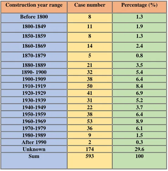
The study further indicated that dams constructed during two periods, 1890-1939 and 1950-1979 appear to have suffered the highest rate of failure as shown in Table 2 [1]. The first period (1890-1939) was a period of trial and error and learning from
Dam Safety: Technical Problems of Aging Embankment Dams 283
mistakes when design tools, input data and construction methods and materials were not available in the way they are today, while the second period (1950-1979) reflects the boom in dam construction all over the world, where even the small probability of failure can result in large number of such failures [1].
One limitation of the statistical approach in predicting dam failures is the fact that site conditions of all studied dams were not the same in terms of geology, hydrology, or seismicity and even in terms of design procedures used. This entails careful scrutiny of all these conditions case by case in judging the possible impacts of age before including them in such a study.
The survival of many old dams suggests that their engineering has been amply conservative, or that their worst trials are yet to come. However, the level of conservatism in the design of an individual dam cannot be determined without a verified comparator. The ultimate measures are the actual behavior under extreme conditions [2].
Table 2: Construction time of the failed earth dams.
Construction year range Case number Percentage (%)
Before 1800 8 1.3 1800-1849 11 1.9 1850-1859 8 1.3 1860-1869 14 2.4 1870-1879 5 0.8 1880-1889 21 3.5 1890- 1900 32 5.4 1900-1909 38 6.4 1910-1919 50 8.4 1920-1929 41 6.9 1930-1939 31 5.2 1940-1949 22 3.7 1950-1959 38 6.4 1960-1969 53 8.9 1970-1979 36 6.1 1980-1989 9 1.5 After 1990 2 0.3 Unknown 174 29.6 Sum 593 100
2. Nature and causes of aging in embankment dams
The aging of dams, whether concrete, masonry or earth fill dams is a natural phenomenon common to all man-made structures, and it is the outcome of an active and never stopping processes of deterioration and decay. As time passes, this degradation continues in dams in a process similar to the aging of human beings, for this is a result of dynamic activities of interactions within the dam components which have inherent weaknesses that are seeded by design or construction procedures in addition to reactions towards the external forces acting on the dam. Degradation processes work in dam foundation and in dam body as well. If dam foundation is within active fault zone, this may cause dam failure in case of a ground movement, whether this is caused by seismic action or loss of shearing strength. Moreover, if the materials of these foundation are highly compressible then large settlement and cracking or loss of freeboard of the dam will follow. Similarly, if the foundation is formed of soluble materials, then the leaching effect of water will erode such materials causing loss of strength and dam collapse. Similarly, if seepage control measures in these foundations, such as cutoffs, grout curtains and relief wells, are not successful then extra uplift and high exit gradient will cause piping and failure.
Degradation within the embankment may happen due a wide range of causes which have negative impacts on its stability if they are allowed to continue for appreciable length of time.
From these causes,
i. High pore-water pressure caused by high water content of the placed fill material and over-compaction which brings with it hydraulic fracturing and gradual piping and failure.
ii. High pore pressure means also reduction of shearing strength and reduced factor of safety against sliding in case of any increase of loading such as in un expected earthquake.
iii. High pore pressure resulting from clogged filters and drainage zones or blankets brings saturation of the downstream and rise of the phreatic surface above the toe of the dam. This clogging is the outcome of either improper design of these filters or due to bad selection of materials. The rise of the phreatic surfaces will cause piping and sloughing with the progress of time.
iv. Improper selection of the embankment core materials by using clays of dispersive or expansive nature which brings dispersion and hydraulic fracturing problems with them, or for the shells, the use of gap graded materials which brings with it suffusion. In such cases piping and internal erosion become highly probable.
All these matters should mean much worry and concern about the safety of the dam, not only to the designers but to the caretakers also. These concerns extend throughout the entire life of the dam until its safe abandonment or demolition.
Dam Safety: Technical Problems of Aging Embankment Dams 285
Design procedures may mitigate effects of aging. Vigilance during construction may correct conditions contributing to aging. Monitoring during operation can identify aging processes which could impact on dam safety. The aging of dams constructed of earth and rockfill materials as discussed here is mainly, however, due to time-related changes in the properties of the materials of which the structure and its foundation are composed.
3. Foundation problems in aging embankment dams
Historical failures show that very high percentage of such failures are caused by foundation defects. These defects have gone unnoticed during investigation and design phases or they were ignored because of the inherent uncertainty associated with their nature. The impacts of these anomalies appear however after many years of service. The failure of Baldwin Hills Dam may serve as a good example. 3.1 The Baldwin Hills Reservoir Dam Case
This dam was constructed in 1951 to impound water into its reservoir to provide water to the south and southwest portions of the city of Los Angeles in California. The reservoir was confined on three sides by compacted earth dikes and the Baldwin Hills Dam on the northern fourth side. The Baldwin Hills Dam had a height of 232 feet and stretched a total of 650 feet in length. Its failure occurred in 1963 after 12 years of service. The designers of the Baldwin Hills reservoir and dam recognized since the beginning the difficulties associated with the site on which they planned to build the structure. But they underestimated the consequences of leakage of the reservoir if such leakage would occur.
At the location of the dam and reservoir, the immediate subsurface was comprised of loose, sandy soil followed by large block-like schist formations. In an effort to prevent water inside the reservoir from contacting the soft erodible soil beneath it, the reservoir was lined with asphaltic lining and equipped with a complex underdrain system. A typical section of the drainage system between the water in the reservoir and the dam embankment is shown in Figure 1. Moreover, the designers acknowledged the Inglewood Fault System that underlies the Baldwin Hills area. They assumed, however, and without any logical reason, that any movement or subsidence that may occur as result of the fault system would not be large enough to compromise the integrity of the brittle reservoir lining [3].
On the morning of December 14, 1963, during a routine daily inspection, the reservoir’s caretaker noticed that water had begun draining from the pipes beneath the asphalt membrane lining in large quantities. Personnel on site engaged the outlet works designed to lower the reservoir in emergency situations and alarm was sounded in the downstream area and 1600 persons were evacuated from their homes.
Figure1: Typical section of Baldwin Hills Reservoir lining.
Despite of all efforts, one section of the Baldwin Hills Dam collapsed after three hours releasing huge destructive wave on the town below. The total release of 950,000 m3 of water resulted in only five deaths, thanks to the early sounding of the
alarm and evacuation of the residence but the destruction of 277 homes could not be avoided. Vigorous rescue efforts averted a greater loss of life, refer to Figures 2 and 3.
As the reservoir completely drained it was revealed that the asphalt lining had cracked allowing water to penetrate and erode the soil beneath it. In the aftermath of this failure there was much speculation of the primary cause(s) of the crack during the investigation and law suits that followed the failure which are outlined in the following.
Dam Safety: Technical Problems of Aging Embankment Dams 287
Figure 2: Baldwin Hills Reservoir Dam showing breach section in the aftermath of failure.
Figure 3: Aerial view of Baldwin Hill Dam Reservoir showing breaching section.
In its investigation, the State Engineering Board of Inquiry determined that the rupture of the reservoir lining which ultimately caused the collapse was result of slow earth movement concentrated at one of the fault lines. This movement was claimed to be caused by the tectonic movement manifested by the general subsidence in the Inglewood fault system area as visualized in Figure 4 [4].
Figure 4: Diagrammatic representation of fault activation attributed to subsidence [4].
Two law suits filed in 1966 by the city and its insurers against the oil companies active in the Inglewood oil field at the time of dam failure charged that the oil operations had led to the events directly associated with the breaching. It was claimed that the injection of water under high pressure used in the extraction of oil may have weakened the uncemented rock, practically causing marked changes in the geologic fabric of the foundation and the earth-crack ground rupture was generally related to high pressure injection of fluid to the previously faulted and subsidence stressed seems. The fault activation leading to ground rupture appears to be a near surface manifestation of stress relief faulting triggered by the fluid injection, a mechanism identified as being responsible for the 1962-65 Denver earthquakes and for the generation of small earthquakes at Rangeley oil field in western Colorado [4]. According to Robert Jansen, a premiere consulting civil engineer, the foundation of the reservoir had been subjected to progressive horizontal stretching, concentrated at the steep fault planes in the soft rock as visualized in Figure 4. The foundation schist blocks under the reservoir literally tended to pull apart and drop down in a staircase, and then rebound. This action formed gaps between the blocks that became ready conduits for leakage once the lining was destroyed [5]. The rupture allowed water to escape into the loose partially consolidated sandy soil under the reservoir and the dam failed [5].
The case of Baldwin Hills Dam serves as good example of slow deterioration process in the underlying foundation which had taken twelve years to result in such sudden failure. In spite of the continuous inspection and monitoring of the reservoir and the dam the real hidden foundation defects escaped the attention and even baffled the investigators afterwards.
Dam Safety: Technical Problems of Aging Embankment Dams 289
3.2 The Wolf Creek dam case
Piping in dam foundations, which can pause threats to dam safety, may result from geological features incorrectly evaluated or underestimated and lead to constant worry and costly repairs over the life of the dam. In this regard the Wolf Creek Dam Case serves as a classic and very illustrative example. This dam is multi-purpose dam on the Cumberland River in Kentucky, United States. It was built by U.S. Army Corps of Engineers to generate hydropower, control flooding; and allow year-round navigation on the Lower Cumberland River by releasing the navigation flow required, and it creates Lake Cumberland for recreation with storage volume of 7.5 Billion cubic meter of water. Construction of the dam began in 1941 but because of World War II and other factors, construction was not completed until 1951.
Wolf Creek Dam is 1748 m long and 79m high dam with a combined earthen and concrete structure. The concrete section of the dam consists of 37 gravity monoliths that make 548 meter of the dam's length across the old river channel. The spillway section contains ten 15.00m x11.00m tainter gates and six 1.20m x 1.80m low level sluice gates. The power intake section contains the penstocks that feed the six 45MW turbines making total installed capacity of 270MW. The embankment section extends 1200 meters from the end of the concrete gravity portion across the valley to the right abutment. This non-zoned embankment is composed of well-compacted, low plasticity clays, from the valley alluvium Figure 5.
Figure 5: Overview of Wolfe Creek Dam, showing both concrete part and embankment.
The dam was built on heavily karstified limestone foundation. This foundation is composed of approximately 70% limestone and 30% shale units. In ascending order, the stratigraphic units that comprise the Highland Rim are the: Ordovician age Catheys, Leipers and Cumberland limestone, Devonian age Chattanooga shale and Mississippian age Fort Payne marine limestone. There is an unconformity between the Catheys and Leipers formations in which the Catheys was likely exposed. Sometime during the late Pliocene or early Pleistocene period uplift and erosion occurred. It is during this time that the karst features are believed to have developed. The Leiper’s formation and upper five feet of the Cathey’s formation are carved with solution features that impact the dam foundation. These two formations combined make up a total of 70m of limestone at the base of the dam. Overall, the bedrock is structurally intact without any faulting at the site. However, there exists jointing that trends both parallel and perpendicular to the dam axis. The systematic joint set that is normal to the dam axis is oriented approximately N 30º W and the limestone is known to be highly karstified. This fact is all the worse for its significant position under Monolith 37 and the concrete-embankment interface. A conjugate set of joints are oriented approximately N 75E, and so being parallel to dam axis. This was the set utilized for the cutoff trench. The intensely karstified Leipers formation exhibits channels and caves developed along the near vertical joints and horizontal bedding planes. Geological section of the dam is shown in Figures 6 and Figure 7 [6].
Dam Safety: Technical Problems of Aging Embankment Dams 291
Figure 6: Geological section of Wolf Creek Dam.
Large cavities and pronounced solution features were encountered during the excavation of the cutoff trench under Monolith 37 and the concrete embankment interface as illustrated by the photograph in Figure 8 [7].
Figure 8: Cavities and Solution Features encountered in Cutoff Trench Excavation [7].
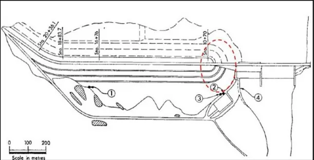
Seepage was first encountered during foundation construction and visible karst features were identified. The seepage problems were traced to the karst geology of the region which allows for the dissolution of limestone, and it is recognized to be in large part due to solution of the carbonate rocks lying beneath the embankment section. It is thought now that the foundation treatment techniques used were inadequate for this condition. Most of the alluvium was left in place and except for the cut-off trench, no treatment for the embankment foundation was performed, moreover, the cutoff trench design and construction were not properly done [7]. After 17 years of service, excess seepage problems within Wolf Creek Dam foundation began to appear. Beginning of 1968, signs of this seepage were discovered when two sinkholes appeared at the downstream toe of the dam and muddy water was observed in the dam's outflow channel. Solution channels caused by this process allow piping to occur which added to the rate of erosion in the foundation Figures 9 and 10. As concerns over this seepage increased one campaign of investigation was started which found solution channels in the limestone, and local piping.
Dam Safety: Technical Problems of Aging Embankment Dams 293
Figure 9: Sinkhole location: (1) sinkhole of 8/22/67. (2) Sinkhole of 3/13/1968.
(3) Sinkhole of 4/22/1968. (4) Muddy water (Tailrace). (///) Wet areas, red dash outlines the “area around monolith 37”.
Figure 10: Sinkhole of 3/13/1968 at the Edge of Switchyard [7]. Emergency grouting over 1968-72 stopped the immediate piping, and it is generally accepted that this had saved the dam, but as recognized afterwards more was needed at the time. Following this, severe foundation seepage problem led to the necessity of a permanent solution at Wolf Creek Dam after the completion of the emergency grouting program completion in 1972. A board of consultants was convened whose adopted recommendations were to install pile type concrete walls diaphragm
through the embankment of the dam and the area between the switchyard and the tailrace. This type of highly specialized work was not done by the USACE before which led to splitting the construction into two phases, with approximately half of the embankment wall and all of the switchyard wall in Phase I, and the remainder of the embankment wall diaphragm, which was the trickier part in Phase II. The walls were comprised of 26-inch steel cased tremie concreted caissons on 4.5 foot centers connected by concrete elements tremied through the excavated trench excavation in between. All excavation was conducted through a full head of bentonite stabilizing slurry. The wall reached a maximum depth of 278 feet, and the diaphragm wall construction was accomplished from 1975 through 1979, and site restoration completed in 1980.
Instrumentation of the dam behavior, after completion of this work was taken very seriously. The dam work was highly instrumented and carefully monitored. The instrumentation system included some 300 open pipe piezometers, pressure transducers, inclinometers, seismic instruments, and surface monumentation. Water temperatures were measured in the piezometers every two to three months. Geodetic monuments surveys were performed semiannually, unless specifically requested, and inclinometer readings were made at three month intervals. No problems were foreseen for the switchyard diaphragm wall. For the diaphragm of the embankment, although the concrete test cores indicated that the more vulnerable portion of the wall, the secondary elements, were probably fully closed, the possibility did exist that there could be windows in the structure. However, there was indications for under-seepage to have resumed below concrete structures founded in so-called sound rook, and constant attention to instrumentation and visual inspection were to be maintained. It was thought then that the most likely future problem would be at the right hand end of the wall following completion of Phase II, and the hydraulic gradient should be monitored closely to determine if future remedial action is to be necessary in this parts [8].
Monitoring of the concrete barrier revealed that the diaphragm wall had slowed but not stopped the seepage and erosion problems. The USACE admitted then that water seepage had found new paths under and around the wall, and even possibly through defects in the wall itself as erosion of solution features continued. The extent of the diaphragm completed in Phases I and Phase II is illustrated in Figure 11.
Dam Safety: Technical Problems of Aging Embankment Dams 295
Figure 11: The first diaphragm wall of Wolf Creek Dam diaphragm wall as indicated in 2004 ([7] and [38]).
Further studies were undertaken over 2004-5, concurrently with USACE's development of its risk-informed safety program looking at all of its dams. Conclusions were that the diaphragm wall did not go deep enough into the bedrock, and it did not extend laterally far enough to intercept all major karst features [9]. Wet areas continued downstream of the dam and in 2006 an independent assessment by the Dam Safety Action Classification (DSAC) Peer Review Panel concluded that Wolf Creek Dam exhibited serious problems and that compelling foundation seepage issues required immediate attention. Reports of seepage has caused public worry and showed that if Wolf Creek Dam failed, the USACE will suffer an estimated $3 billion in property damage in such an event. An economic analysis of the new rehabilitation works had suggested 7:1 benefits/cost ratio. All this, triggered the most complex dam foundation remediation project of any dam in the world excluding the case of Mosul Dam foundation works (Iraq). The total cost of estimated for Wolf Creek Dam was $594 million, requiring six years of construction (2007-2013).
In Mosul Dam, the rehabilitation of the grout curtain alone had continued from 1986 up to now costing billions of dollars including 2.0 billion dollar program in 2016-2018 alone.
The new remediation works of Wolf Creek dam was again divided into two phases. The works of Phase I were awarded to Advanced Construction Techniques (A.C.T.) and work on this phase began in March 2006. To reduce stress on the Wolf Creek Dam and therefore risks during the remediation works the Cumberland Lake water level was lowered by 25 meters below the normal summer levels and the project
was considered the number one top priority in the United States at that time. The scope of work consisted of a double line grout curtain to depths of 330ft within the limestone foundation material. The purpose of this grouting was to reduce the residual permeability of the dam foundation as a pre-treatment for the proposed new diaphragm wall installation. The activities also required construction of a 4,000ft long work platform and environmental collection and treatment ponds to support the drilling and grouting operations. The sequence of work required drilling through the embankment overburden and installation of permanent casing up to depths of 180ft seated into the embankment rock interface utilizing sonic drilling methods. Continuous sampling and logging of the embankment material were performed to determine clay core integrity. Site characterization was determined by exploratory drilling using rotary diamond core drilling with continuous sampling and logging of rock cores together with water pressure testing and video imaging. Foundation rock drilling was performed with water actuated down the hole hammer followed by borehole washing, permeability testing and pressure grouting using balanced stable high mobility grouts. Special procedures and grout mixes were developed to treat karst solution features encountered within the rock foundation. Gallery drilling and grouting using rotary diamond drilling, water flush, permeability testing and pressure grouting was also required. IntelliGrout®, a proprietary computer monitoring system was utilized for real-time electronic monitoring and recording of the permeability testing and grouting [9].
In April 2009, construction began on Phase II which was to build a second diaphragm. Plans were developed for this new cut-off wall to be deeper, wider, and to be immediately upstream of the first one. Main contractor for the works was Treviicos-Soletanche JV. Construction commenced in 2006-7 with a scheduled completion target of late 2013.
The reservoir was temporarily lowered to reduce risk until completion of the diaphragm wall. The water level was kept in this case 13.1m below the crest elevation of 220.4m a.s.l. sufficient to satisfy the minimum “power pool” for hydroelectric power generation. The new diaphragm was designed with a minimum thickness of 610mm as measured across the three types of construction employed which were overlapping panels, secant piles, and a panel-pile combination. It was excavated down through the clay embankment to sit in the top 610mm of bedrock. The panels were 1.83m wide by 2.8m long, and overlapped at least 127mm. Concrete was placed by tremie, working up from the base of the excavation and displacing the slurry support. Compared to the era of the first cut-off wall, the new deep foundation project was able to call upon more advanced construction systems, and data monitoring and analyses.
In total, the new wall was designed to be approximately 1158m long and up to 83.8m deep penetrating up to 29m into the bedrock, making it up to 22.9m deeper than the original cut-off wall which has a variable bottom profile. The diaphragm was completed in 2013 and lake levels returned to normal in 2014 [10].
The diaphragm work of Wolf Creek dam led Donald Bruce, the well-known grouting and diaphragm construction specialist to propose one theory which states
Dam Safety: Technical Problems of Aging Embankment Dams 297
that advances in specialty geotechnical construction techniques are not gradual and progressive. Rather they take the form of “Great Leaps” triggered by specific project challenges. He qualifies as a “Great Leap,” the deep remedial cutoff completed at Wolf Creek Dam, which has given good test to this theory [11].
All the proceedings, however, prove one important fact that geotechnical problems themselves do not arise as “Leaps”, but rather can either take many long years of operation to show their manifestations, or immediately on the first impounding of the dam as had happened in Mosul Dam mentioned already. This dam completed in 1986 was built on poor foundation containing gypsum-limestone karst formations. Construction of the grout curtain was met with considerable difficulties upon the refusal of the gypsum breccia layers to accept any form of grouting. The first impounding of the dam with open widows in the curtain led to increasing seepage flow under the rising hydraulic head of the reservoir and causing increasing dissolution of gypsum which had threatened the stability of the dam. Remedial grouting works have been ongoing since 1986 up to now except for the period between June 2014 to April 2016 when the grouting works and all other activities were suspended at the site for fear of ISIS attacks on the site. But luckily resumption of these works was possible later on in a new intensive phase with $2 Billion cost and completed in 2018. The grouting is deemed to continue for the whole life of the dam. This is probably the longest and more costly foundation remedial grouting work ever undertaken all over the world up to now. The dam still forms a threat to six million inhabitants in the downstream waiting for a permanent solution, which may be in the form of diaphragm or constructing a protection dam downstream. The full story of this dam was summarized by three papers [12], [13] and [14].
4. Aging problems in embankments of fill dams
Degradation in the structural properties of fill dams of any type may be due to actions affecting their embankment as result from external forces, or from the nature and properties of the material of which the embankment is constructed and from procedures used in its construction. Such deterioration can also be caused even by improper design. With the passage of time signs of decay may in many cases appear after long years of operation while they had escaped the attention of inspectors during past years. Constant vigil over dam safety and concentrating on even the smallest related details and taking them seriously may save the dam by taking timely actions. Old dams can be more vulnerable to the development of defects as result of accumulation of causes and magnification of impacts during the long service life. The outcome may show as deformation, loss of strength, pore pressure increase, internal erosion, etc. which all contribute to less stable dams.
4.1 Embankment deformation
Earth fill embankments undergo long process of consolidation which starts with the compaction of the fill materials during construction resulting in “Initial Consolidation”. Consolidation, however, continuous for a very long time during the operational life of the dam and it is known then as “Primary Consolidation”. Primary consolidation will slow down after these years, subject to initial degree of saturation of the fill material, type of materials and their mineral composition in addition to mode of operation and ambient environmental conditions. Final stage of consolidation is called “Secondary Consolidation” which is taken to mean all of the compression that follows the “Primary Consolidation”.
Consolidation is caused by the dissipation of pore water pressure in the clays and the continuous settlement of all materials forming the body of the embankment [15]. Although most of the settlement occurs in the first few years after end of construction as result of primary consolidation, more but little settlement will continue during secondary consolidation. The result of these accumulated settlements may show in the form of progressive cracking and deformations which can be uneven along the dam length and may lead also to differential settlement in adjacent sections or in contact sections with abutments and concrete structures causing more cracking and fissuring. This cracking will lead to increased seepage and possibilities of internal erosion with the passage of time. Cracks and fissures can develop severely and become real threats if the dam is subject to sudden settlements from seismic ground movement in earthquake events. Generally speaking, cracking may be caused by differential foundation settlement, differential embankment compression, embankment arching “Hydraulic Fracture”, separation in the contact with concrete structures, or drying out of the upper portion of the core during prolonged dry periods. Loss of freeboard is another side effect of large settlements, which endanger dams’ safety if this was not anticipated and taken care of in the design stage.
4.2 Improper construction
Inferior construction procedures and not following strictly proper specification can lead to potential threats which appear later on after the passage of appreciable length of time. Wetting of improperly compacted embankment soil can lead to loss of strength. Materials compacted dry without the necessary compaction effort to sufficiently reduce the void volume will experience considerable particle reorientation and consolidation, and if a large mass of embankment are affected this results in large differential settlements. If occasional layers or lenses of different material are present in the fill, then such layers or lenses will show different behavior than the general mass which reflect in different compression and may lead to cracking and differential settlement within the dam itself and possibly lead to piping and areas of different pore pressures. This demonstrate the importance of using uniformly homogenous materials throughout the clay core since variation of these material properties can result in erratic behavior of the soil mass. Using different materials of different characteristics in different horizons may cause
Dam Safety: Technical Problems of Aging Embankment Dams 299
separation of layers which leads to hydraulic fracturing. Such case was partly blamed for the Teton Dam (Idaho-USA 1973) failure.
4.3 Loss of strength during operation
Many scenarios may be visualized regarding such loss of strength with the passage of time and mean lesser stability in the end. These may be one or more of the following:
i. Some dam materials can experience large reduction of cohesion as in clay cores, and reduction of the angle of internal friction in granular as in shells when they are continually wetted. Reservoir seepage, intensive rainfall wetting the downstream shell and very frequent draw down of the reservoir affect stability by reducing the aforementioned shearing strength parameters and the factors of safety against slope slides originally calculated. From the fact of their long lives, old dams may face critical situations due to unanticipated loading conditions such as greater than the anticipated floods, or in case of unaccounted severity of earthquakes. These unanticipated conditions combined with reduced factors of safety causes great stability concerns over such dams. The mechanical characteristics of fill materials and thereof the calculated design factors of safety cannot be guaranteed over such long time for old dams.
ii. Loss of strength may be caused by change in the state of stress within the dam with increasing pore pressure. Any increase in pore pressure in clay core results in pressures greater than estimated from normal permeability tests of the compacted soil and this is generally associated with opening up of transverse cracks in the core or through the whole fill. Pore pressure increase may be associated also with such matters as dissolution of dispersive clays, defective layer in the core, poor material placement, bad design of the filter and drainage zones which result in low permeability downstream of the core. Good design and construction practices may preclude excessive pore pressure increase by the appropriate selection of graded filter material and careful placement of filter zones and drainage layers. Moreover, eliminating foundation overhangs, and shaping the contacts with the abutments and foundations, use of ductile material in the upper part of the dam and adequate drainage downstream. Watching for any abnormal pore pressure increase is done by using pore pressure measuring cells and observing the development of this phenomenon. Generally, in normal cases these cells show decrease of pore pressure with time as excess pressure is dissipated gradually through the primary consolidation process. Any sudden increase should point out to unhealthy condition which requires immediate attention to pin point the reasons and find a proper way of treatment in time. In many cases it is customary to observe sudden surge in pore pressure after an earthquake. The magnitude of this surge depends on the magnitude of settlement caused by the earthquake which result in more consolidation and also the opening up of cracks. Careful study and analysis
after such event is necessary to evaluate the general condition of the dam. Older dams are more prone to such influences with progress of time. iii. Embankment heightening of an earthfill dam may stress the existing
material beyond its peak strength and a lower residual strength is reached. Such heightening is required after the need of such increases due to increasing demand on water brought about after long period since the dam was commissioned. It is advisable that such work is not attempted before careful study of the old dam material characteristics to ensure not stressing them beyond their tolerated capacity.
iv. Cycles of drying and wetting of high plasticity clays may cause in slope instability and sliding failure particularly shallow downstream slips. As the clay dries, capillary stresses lead to cracking by surface tension. When water is again available to the crack, material sloughs off into the crack and there is a loss of strength in the swelling clay at the crack face.
A progression of these events during the long life of an old dam would reduce the effective dam width and promote other scenarios.
4.4 Internal erosion in embankment dams
Internal erosion is one of the most dangerous threats to fill dams’ stability. This may go unnoticed for a long time, but generally finds its origin in design and construction inadequacies. It may occur in dispersive soils susceptible to piping and cracked soil mass in the embankment. Internal erosion may happen within the embankment core or in the downstream shoulders if the phreatic surface daylights above the toe of the embankment. Quite frequently it occurs at the embankment contact with the foundation as the case was in Teton Dam failure. Erosion of embankment material may be through fissured rock or into solution cavities along with erodible rock fissure infilling within the dam base and abutments which enhance seepage flow. Erosion of embankment is commonly via embankment cracking and inferior protection by filters. Characteristics and origin of the material used can help in internal instability of the earth fill. Use of glacial moraine till, dispersive clays, or leaching of soluble minerals exasperate the erosion process if it starts. Removed of material by erosion induces settlements and local failures occur as sinkholes. Detection of internal erosion has relied on visual inspection, water flow measurements, pore pressure readings, and turbidity measurements. Drilling using sonic drilling or other drilling method without drilling fluid, geophysical investigations such as temperature measurements and magnetic resonance imaging or by the use of geo-radar have been carried out to determine the extent of the erosion. Remediation of such problems can save the dam if they are discovered at an early stage of its development. Measures to be taken depending on each case may include grouting the piping path, diaphragm wall installation, drain system replacement and replacement of affected embankment section. Progression of internal erosion is characteristic of dams after appreciable service time.
Dam Safety: Technical Problems of Aging Embankment Dams 301
4.5 Mechanical degradation of embankment materials
This implies changes of the physical properties of the fill materials which result in change of strength or increased permeability of the material in question. These can result from:
i. Increasing seepage which is an important element for the degradation processes as it may cause removal of erodible, soluble, or dispersed material. Saturation may cause loss of shear strength.
ii. Some rock types, particularly shales, deteriorate when exposed to air and moisture in an unconfined condition. If shales are used in a rockfill, they may deteriorate or weather into a soil resulting in surface deformation or lowered shear strength of the rockfill allowing slope instability.
4.6 Surface erosion of embankment slopes
Surface erosion, although a very common aging scenario, has not been an important contributor to embankment failures. Surface erosion is readily detected by routine visual inspection and repairs would be undertaken in a timely manner. Erosion on the downstream slope and crest may be due to heavy direct rainfall or surface water runoff, brief crest overtopping, wave spray over a wave wall or wind driven wave spray. Erosion on the upstream slope may be due to wave action on too small riprap or from inadequate bedding, breakdown of riprap or even from freezing and thawing displacement. Timely repair of upstream and downstream slope erosion is important. Downstream slope improvement includes directing crest runoff into the reservoir and collecting and diverting surface water down and away from the downstream slope. Regular visual inspections particularly following unusual weather events are necessary.
4.7 Burrowing animal impacts on earthen dams
The damages caused by beavers, rodents, and other forms of borrowing animals over a long period of time often appear as minor and small burrows, shallow dens, however, may lead to progressive erosion. Limited erosion may not trigger a dam owner’s concern, but in many reported cases minor damages such as these are often
at the core of unsafe dam operations or outright failure specially of old dams. The most significant and often least obvious impacts of wildlife intrusions may be
described in the following: 4.7.1 Hydraulic alterations
Burrows on the upstream and downstream slopes can dramatically alter how a dam controls the water pooled behind it. Dramatic changes to the designed hydraulic function of a dam include:
i. Shortened seepage paths. ii. Increased seepage volumes.
iii. Increased probability of slope failure.
iv. Internal erosion of embankment materials (piping), which can rapidly
In addition, beaver mounds may block principal and emergency spillways and riser outlets, resulting in,
i. Increased normal pool levels and reduced spillway discharge capacity. ii. Sudden high discharges from the dam if an upstream beaver dam fails. iii. Clogged water control structures as debris from an upstream beaver dam
floats downstream and,
iv. Erosion of the downstream toe as a result of elevated tailwater caused by beaver activity in the downstream reach.
4.7.2 Structural integrity loss
Many species excavate dens and burrows within embankment dams, causing large voids that weaken the structural integrity of the dam. Typical voids can range from the size of a bowling ball to a beach ball and much larger, and can cause many adverse structural impacts. Localized burrow collapse can occur due to heavy rain and snow melt or by heavy equipment or vehicle use on the crest. Collapsed burrows can progressively lead to sinkholes or depressions on the embankment surface. Collapsed crest soils can result in loss of freeboard, thus endangering the dam during storm events. Massive slope instability can result from collapsed burrows and soil losses.
4.7.3 Surface erosion
Wildlife that graze or traverse areas of open vegetation associated with dam embankments can cause a widespread loss of vegetative cover.
This increased feeding and traffic pressure on the dam’s vegetative ground cover can lead to:
i. Erosion paths.
ii. Decreased soil retention on the dam’s crest and slope.
iii. Increased rates of soil erosion because of the lack of stabilizing vegetation from grazing and trafficking.
iv. Irregular surface erosion and the formation of rills and gullies, and,
v. Reduction in freeboard and loss of cross section, and in turn, an increase in the dam’s vulnerability to damage from high water during large storm events [16].
4.8 Loss of bond between concrete structures and embankment, and damaged complementary materials
The deterioration of embankments adjacent to concrete structures is associated with differential movements in the contact zone. Displacements of the bonding zone may be due to settlement of the embankment material caused by inadequate compaction or internal erosion. Settlement of the foundation due to inadequate treatment may also be another cause. Settlements may lead to arching in the fill and a reduction of the effective stress. Moreover, seepage develops through cracks in the fill or along the concrete structure promoting internal erosion and failure if the filter-drainage system is insufficient. Aging of complementary materials used in dam construction, such as geosynthetic materials, asphalt concrete facing, soil-cement protection which are subject to weather elements and stresses due to settlements, abrasion, and
Dam Safety: Technical Problems of Aging Embankment Dams 303
ware due to moving debris and other agents can cause serious damage to these materials and may speed up the aging process of the dam itself and contribute to safety problems in such dams [17].
5. Lewisville Lake Dam an aging earth fill dam case study
One example of progressive deterioration in earth fill embankment dams with passage of time may be cited from the case of Lewisville Lake Dam in Texas (USA) completed in 1955 by the US Army Corps of Engineers. This case also shows the continuous concern over its safety expressed by the Corps who have been responsible for the dam’s safety since then and considered it in 2005 to be very high risk dam among their more than 700 dams according to risk assessment study. This risk assessment merits consideration of the long term.
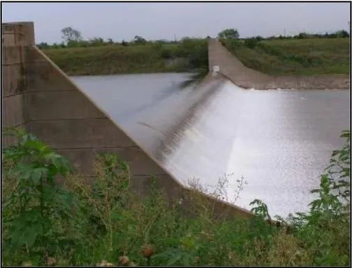
The objectives for creating the Lewisville Dam lake reservoir were flood control, serving as water supply source for Dallas City and its suburbs, but residents also use it for recreational purposes. The main components of the project are uncontrolled concrete ogee weir spillway structure and earthen embankment section. The ungated spillway is located on the left abutment of the embankment. The structure consists of an approach channel, uncontrolled concrete ogee weir with a crest elevation 532.0 feet above mean sea level, two 90 feet long concrete gravity non-overflow sections, paved apron, retaining walls, and an unlined discharge channel. The reinforced concrete apron slab is about 209 feet long and 551 feet wide. The slab was built with a 10 feet deep turned-down cutoff at the end of the original apron slab. The reinforced concrete cantilever retaining walls are about 13 feet high and extend the length of the concrete apron. Twenty-eight foot high wing walls are located at the downstream end of each retaining wall. The spillway is designed to pass a discharge up to 6136m3/sec. The spillway has no stilling basin, and, because
of high velocity discharges it was severely eroded at the downstream end of the sill during the uncontrolled releases of 1981 and 1982.
Repairs were made to the spillway and downstream riprap in many occasions between 1966 and 1988 which had included extending the concrete apron 60 feet downstream with 18 inch reinforced and anchored concrete slab and 10 feet deep cutoff wall at the downstream end of the new slab. Additionally, 24 inch thick riprap was placed at the downstream end of the new slab for a distance of approximately 30 feet. Much of this riprap was redistributed during the uncontrolled releases that followed heavy rains in May 2015. Repairs to restore the original riprap design were done as part of normal operation and maintenance activities.
Figure 12: Lewisville Dam: view of spillway Ogee Weir looking east. The earthen dam is 32,328 feet long, with a maximum height of 125 feet and crest of 20 feet width. The dam was designed as an impervious structure and it was built using materials obtained from onsite borrow sites and excavations. Also incorporated into the design of the dam was 3 to 4 foot thick granular drainage blanket underneath the downstream section of the embankment. The foundation is made up of clayey sands and sandy clays [18]. The dam holds 6.85 x10⁹m3 of water
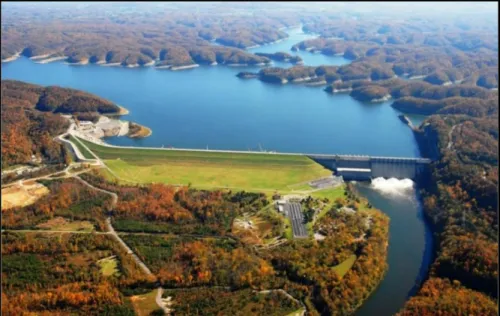
when the lake is full to its maximum depth of 20 meters. Aerial views of the dam are shown in Figures 13 and 14 indicating the extent of the dam length and some of the details of the inhabited areas downstream.
Dam Safety: Technical Problems of Aging Embankment Dams 305
Figure 13: An aerial view of Lewisville Dam indicating the various components of the dam.
Figure 14: An aerial view of Lewisville Dam showing location of boggy area created by seepage.
A typical section of the dam is shown in Figure 15 which illustrates type of materials and details of the dam while Figure 16 is a schematic diagram which indicates the operation water levels and shows also the type of geology under the dam which can
be very much inductive to seepage problems in the downstream. With this type of geology and in the absence of seepage control measures in the
foundation, other than the shallow cutoff trench, it is not surprising therefore that the dam had suffered from seepage for many years, whereby three seepage areas
were identified in the downstream of the dam.
Figure 15: Typical cross section of the Lewisville Dam Embankment.
Figure 16: An exaggerated schematic diagram showing Lewisville Dam Embankment cross section and foundation geology.
The outlet works of the dam consist of an intake structure, conduit portal unit, stilling basin, a service bridge, and reinforced concrete wing wall located on the upstream end. It is equipped with three flood-control openings controlled by three service gates. Two reinforced concrete service conduits go out of the intake structure, each of them is 4.87m in diameter and 135.6m long and equipped with valve at its end. Each of the valves is located in a conduit portal unit at the downstream and used for diverting low flows either to the stilling basin, or to the
Dam Safety: Technical Problems of Aging Embankment Dams 307
penstocks for the non-federal hydropower facility. The stilling basin consists of a parabolically curved, reinforced concrete apron with the slab and training walls. The stilling basin is 54.8m long and is approximately15.8m wide at the end sill and provided with wing walls at the downstream end.
The dam began to show signs of severe deterioration at an early date after commissioning. But in 2008, a group of Corps engineers performed an in-depth assessment of the dam safety and discovered some serious defects; seepage under the foundation was creating pressure and uplift conditions at one end of the dam. There were signs of embankment instability during “extreme loading conditions” under rapidly rising reservoir. The spillway suffered from erosion and structural distress. The same team concluded the “likelihood of failure from one of these occurrences, that this likelihood was too high to assure public safety”, and, the dam posed “very high risk” to the population centers downstream namely: Lewisville, Coppell, Carrollton, Farmers Branch, Irving, Las Colinas, Dallas and points south. The Corps had prepared maps of the inundation area which showed that 431,000 people will be at risk. One general map of the will be inundated area is given in Figure 17.
Figure17: General map of the inundated area downstream of Lewisville Dam in case of dam failure.
The analysts’ findings were supported by another study done by another team of engineers who identified significant potential failure modes with respect to the project condition and the potential downstream consequences. Worries about the safety of the dam continued during the following years and in a public meeting held in Lewisville in 2013, Corps officials acknowledged the uncontrolled seepage, the potential instability of the spillway and embankment and other areas of concern. But they assured the public that the Corps had implemented a number of temporary risk-reduction measures to address the problems while pressing ahead with further studies to determine the best methods to fix them [19]. As events unfolded later on, it was in 2015 during the height of the record rain storm in May 2015, as floodwaters began filling the Lewisville reservoir, the safety inspection team kept a vigil to observe signs of distress for about six weeks in May and June. The higher the water rose in the reservoir, the greater the pressures on the Lewisville Dam became. So, when an instrument reading showed pressure rising at “Seepage Area No. 1”, the same area where the Corps specialists had worried for years that excessive seepage could cause a rupture or blowout, a sand boil was found in the boggy area which looked like a whirlpool spinning and spouting from underground. This indicated that excessive seepage was starting to erode soil material from the downstream slope or foundation of the dam through to the upstream side to form a pipe, or cavity, to the reservoir in retrogressive internal erosion processes. It was recognized as the beginning of piping failure and internal erosion; the structural integrity of the dam was already compromised and complete failure of the dam was threatened. An emergency action was initiated by placing one-layer ring of sandbags around the sand boil allowing the pool of water inside to rise about six inches. Such action is normally taken to equalize the pressure and prevent the water and soil particles from eruption.
At the same time emergency coordinators prepared to begin evacuations in their communities. But the sandbagging worked and the boil, which had surfaced May 17, subsided in a matter of days. And the evacuations were called off and major catastrophe was averted.
Troubles at the Lewisville Dam, however, were far from over. On June 23, 2015, an extensive slide on the upstream face of the embankment,160 feet long and 23 feet wide occurred. Fortunately, this was not a deep seated slide and it did not extend into the foundation of the dam. The location of the slide was adjacent to an earlier major slide that happened in 1995 suggesting to the engineers’ instability within the embankment.
The photograph in Figure 18 shows the slide which was covered with plastic tarps, sandbags, and wooden planks for fear of more heavy rain causing more damage. Longitudinal cracking at the crest edge as the one shown in Figure 19 had also existed for some time and the cyclic saturation of the upstream face due to rising and falling water surface had induced failures in the saturated mass of soil. Wave action and changing water level due to operational requirement and rapid rise and fall during short floods must have had all contributed to these failures.
fine-Dam Safety: Technical Problems of Aging Embankment fine-Dams 309
grained soil and clay used to build the 10 kilometer long embankment shrinks during droughts and swells during rains, reducing the slope’s shear strength, which means the embankment is brittle when it is dry and spongy when it is wet.
The embankment stability was more questionable since the May, 2015 flood because cracks have spread along the 6 meters wide crest of the dam. The Corps believed that “desiccation cracking” at the crest of the dam caused the earthen slope to collapse and slide. The heavy rains in mid-May and early June of 2015 filled the 1 to 3 inch wide cracks, saturating the soil underneath and vastly increasing its weight while reducing its shearing strength had all caused instability and sliding. This dramatic shrinking and swelling of the embankment materials during the rapid drought-to-deluge cycle may also account for another deformity that were spotted on the upstream face of the dam after the May rains which was a large, bowl-like depression in the slope across from Seepage Area No.1.
Figure 18: Slide area covered with plastic tarps, sandbags, and wooden planks for fear of heavy rain causing more damage [20].
Figure 19: Typical cracking on Lewisville Lake Dam with clear signs of aging.
The envisaged solution was to surround the slide area at the upstream side by a cofferdam, pump dry the enclosed area to enable heavy-duty construction work below the reservoir’s waterline. The contract for this repair work was awarded as a $6.4 million contract to repair the slide in late 2015; it was scheduled to begin on 4th Jan, and should be completed by May 2016 [21].
The works went ahead as scheduled, but close to construction completion another
small slide of about 850 cubic meters occurred which was replaced also. Since the soil used in the dam contained high amount of clay, which expands and
contracts with moisture, the Corps replaced the failed material of the sliding slopes
with lime-stabilized soil taken from borrow area downstream of the dam. The progress of work in this case of repair is shown in Figure [20]. But as it was
coming to the final stage of adding the slope protection riprap to the newly constructed slope [22].
Occurrence of more of such sliding failures in the dam slopes with the progress of time cannot be ruled out, as the same soil and hydraulic conditions prevails along the whole length of the dam. Yet preventing of another massive slide at the Lewisville Dam may not be as easy as fixing the last one. Taken together, the increased seepage, the boils, the piping, the progression of cracking, the slides, the depression and other signs of serious distress, since the 2015 flood, have all indicated that the work of aging process within the dam was progressing at a high rate which merited serious upgrading works to avoid the high safety risks on one hand, and for the sake of continued benefits of the dam on the other.
Dam Safety: Technical Problems of Aging Embankment Dams 311
Figure 20: Repair work progressing on the slope of Lewisville Dam slide during 2016 [22].
Major repairs were already done since the project was commissioned which included,
i. Repair of riprap (November1966-May 1967).
ii. Embankment upstream berm modification (July 1979-May 1980). iii. Embankment and downstream berm (May 1981-November 1983). iv. Upper slope rehabilitation (June 1983-April 1984).
v. Spillway repair (September 1984-September 1985).
vi. Spillway wall and spillway slab repair (October 1987-May 1988).
vii. Upstream embankment and erosion repair (October 1995-July 1996). It was recognized also since 2013, even before the damages of the 2015 flood, that
the dam’s safety was at risk. Studies under the Corps’ Risk Assessment Process had confirmed the existence of unsafe conditions and recognized that the actual level of risk within the dam was high [23].
A preliminary study was made at that time to establish areas of concern which was followed by more rigorous risk assessment to show the impacts of such defects and their influence on safety and laying the ground for remedial actions to be taken to reduce them to tolerable levels.
So, in 2015, after the event of May-June flood these remedial actions were elaborated and were presented in a meeting on November 16, 2015 [24].
The following safety issues were identified, and the possible actions were indicated in the 2013 and 2015 assessments,
i. Uncontrolled seepage through foundation was creating unsafe conditions which could develop into piping and lead to erosion of the embankment. This seepage had created boggy areas downstream of the dam and even formed some noticeable water streams as shown in Figure 21. Potential corrective measures ranged between adding filters, toe drains, berms and cutoffs, or combination of all of these measures as suggested in Figure 22.
Figure 21: Uncontrolled seepage water from under the dam found in various area downstream.
Dam Safety: Technical Problems of Aging Embankment Dams 313
ii. Embankment Stability was an issue of concern under conditions of higher pool levels due to very high floods. The situation can be aggravated in view of the type of soil materials in the foundation and the embankment itself. The loose and brittle nature of the soil is illustrated in Figure 23.
Figure 23: Fine materials used in the construction of the embankment. Stabilization of the embankment was necessary under the failure scenarios considered. The corrective measures could vary between many alternatives; such as, flattening of the slopes and increasing embankment cross section, adding berms, and incorporating filters, or combination of any or all these solutions, Figure 24.
iii. Stability of Spillway Weir: Studies showed that the uplift pressures from ground water acting on the spillway weir have the potential to initiate progressive failure of spillway components and the underlaying foundation materials, so potential solutions varied between anchoring the weir and apron by installing four post tensioned anchors through the concrete into the foundation to prevent sliding, or buttress the weir with piers wedged at the downstream end to increase sliding resistance of the structure. Moreover, a geotextile membrane could be laid on the upstream apron to reduce the amount of water that can get beneath the concrete structure and elongate the seepage path reducing uplift. The downstream spillway apron can also suffer from high uplift pressure and therefore measures to reduce the possibility of sliding and initiation of progressive structural failure must be taken by overlaying the existing slab by a new concrete slab together with installing drainage system between the new and old slabs, or removing the whole apron and install a drainage system underneath a new one Figure 25, shows two views of the spillway during operation (on the left) and another view (on the right) of it while not working and showing cracks in the apron [24].
Figure 25: to the left, view of the Spillway when overflowing; to right view of the weir when not working showing cracks in the downstream apron.
Dam Safety: Technical Problems of Aging Embankment Dams 315
iv. Spillway Outlet Channel Instability; Problems of stability were encountered during construction and operation of this earthen outlet channel where many slide collapses had occurred in its the side slopes. These failures were continuous problematic issues during the service life of the dam, and they needed; therefore, permanent solution to enhance their stability. The extent of the damaged reach may be visualized by referring to Figure 26.
Figure 26: Stability problems of the spillway outlet channel.
Summarizing all safety issues, their implications on the dam itself and the whole downstream environment with the mitigation measures was done in a study titled “Environmental Assessment Proposed Dam Safety Modification-Lewisville Dam Elm Fork of the Trinity River Lewisville-February 2017”. The study was completed by the USACE to decide on possible future courses of action.
It materialized in the following alternative which were,
i. Take no action alternative; this was rejected for not ensuring the requires
safety standards. ii. Achieving only the tolerable risk limit for life-safety, this was also rejected
for the same reason.
iii. Meeting full tolerable risk guidelines; this was the selected alternative, as it answers all safety and environmental requirement and at the same time it is
the lower cost one.
The following last two alternatives were not satisfactory for the indicated reasons: iv. To replace the dam with a new earth fill dam constructed to modern
best safety rating applied to USACE dams nation-wide. The USACE did not consider this alternative viable because it was believed that lower cost alternative.
Would effectively reduce risk, therefore, the extra costs associated with this potential alternative are not justified. Furthermore, environmental impacts associated with removing and replacing the entire dam would likely be substantially greater than those resulting from any of the considered action alternatives.
v. To remove the dam; this alternative was not considered by judging it to be not viable because of the resulting annual flood damages and lives at risk downstream in addition to loss of water supply, recreational benefits, the loss of power generation, and the cost of removal. This alternative was not considered as meeting the purpose and need of the Proposed Action. The selected action plan (iii) was actually evaluated after all possible failure modes were analyzed and their drives were investigated.
The failure modes were,
i. Erosion of the embankment caused by seepage. There are three areas with high rates of seepage, two of which were identified as risk-driving potential failure modes (PFMs). Erosion can occur underground if there are cavities, cracks, an unprotected exit, or other openings large enough so that soil particles can be washed into them and transported away by seeping water by piping. The piping and erosion could rapidly progress and erode the dam leading to a complete breach. Water supply pipes downstream of the toe of the main embankment also may provide a potential seepage route. A pervious sand deposit overlying the bedrock and located beneath the embankment has provided a pathway through which clear seepage and undesirable uplift pressures have occurred at the toe of the embankment. In all, the existing seepage control features are not considered sufficient to prevent initiation of a piping failure.
ii. The spillway erodibility potential failure modes. These may result from; First, loss of the spillway crest and partial loss of the reservoir, or; Second, from extremely high water releases over the spillway which causes erosion of the spillway channel downstream of the spillway concrete apron and could potentially shift the apron panels.
The proposed remediation alternative under action plan (iii) was formulated then with multiple combinations of potential remediation actions for each PFM, but using different groups of measures to do so. Eight combinations were developed for further study. These combinations are listed in Table 3.
![Table 1: Age of failed earth dams at time of failure [33].](https://thumb-eu.123doks.com/thumbv2/5dokorg/4426883.106507/2.813.176.637.557.923/table-age-failed-earth-dams-time-failure.webp)

![Figure 4: Diagrammatic representation of fault activation attributed to subsidence [4]](https://thumb-eu.123doks.com/thumbv2/5dokorg/4426883.106507/8.813.132.682.234.448/figure-diagrammatic-representation-fault-activation-attributed-subsidence.webp)

![Figure 8: Cavities and Solution Features encountered in Cutoff Trench Excavation [7]](https://thumb-eu.123doks.com/thumbv2/5dokorg/4426883.106507/12.813.130.686.191.581/figure-cavities-solution-features-encountered-cutoff-trench-excavation.webp)
![Figure 11: The first diaphragm wall of Wolf Creek Dam diaphragm wall as indicated in 2004 ([7] and [38])](https://thumb-eu.123doks.com/thumbv2/5dokorg/4426883.106507/15.813.135.679.108.478/figure-diaphragm-wall-wolf-creek-dam-diaphragm-indicated.webp)